
VACON
®
NXS/P AC DRIVES
QUICK GUIDE
EN
GUIDE RAPIDE
FR
KURZANLEITUNG
DE
GUIDA RAPIDA
IT
GUÍA RÁPIDA
ES
GUIA RÁPIDO
PT-
BR
快速指南
ZH
PIKAOPAS
FI


3
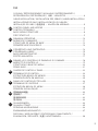
TOC
COOLING / REFROIDISSEMENT / KÜHLUNG / RAFFREDDAMENTO /
REFRIGERACIÓN / REFRIGERAÇÃO / 冷却 / JÄÄHDYTYS ................................4
CABLE INSTALLATION / INSTALLATION DES CÂBLES / KABELINSTALLATION /
INSTALLAZIONE DEI CAVI / INSTALACIÓN DE LOS CABLES /
INSTALAÇÃO DO CABO / 电缆安装 / KAAPELIEN ASENNUS .........................5
CONTROL PANEL AND KEYPAD ........................................................................6
CONTROL TERMINALS ......................................................................................7
BASIC MENU STRUCTURE ................................................................................8
FIRST STARTUP ...............................................................................................9
PANNEAU OPÉRATEUR ...................................................................................10
BORNES DE COMMANDE ................................................................................11
STRUCTURE DE MENU DE BASE ...................................................................12
PREMIÈRE MISE EN SERVICE ........................................................................13
STEUERTAFEL UND TASTENFELD .................................................................. 14
STEUERANSCHLÜSSE .....................................................................................15
BASISMENÜSTRUKTUR ................................................................................16
ERSTES ANLAUFEN ........................................................................................17
PANNELLO DI CONTROLLO E PANNELLO DI COMANDO ...............................18
MORSETTI DI CONTROLLO ..............................................................................19
STRUTTURA DI BASE DEI MENU .................................................................... 20
PRIMO AVVIO ...................................................................................................21
CUADRO DE CONTROL Y PANEL .....................................................................22
TERMINALES DE CONTROL ............................................................................23
ESTRUCTURA BÁSICA DE MENÚS .................................................................24
PRIMERA PUESTA EN MARCHA .....................................................................25
PAINEL DE CONTROLE E TECLADO ................................................................26
TERMINAIS DE CONTROLE .............................................................................27
ESTRUTURA BÁSICA DO MENU .....................................................................28
PRIMEIRA INICIALIZAÇÃO ..............................................................................29
控制面板和键盘 ................................................................................................ 30
控制端子 ........................................................................................................... 31
基本菜单结构 ...................................................................................................32
首次启动 ........................................................................................................... 33
OHJAUSPANEELI .............................................................................................34
OHJAUSLIITTIMET ...........................................................................................35
PERUSVALIKKORAKENNE ..............................................................................36
ENSIMMÄINEN KÄYNNISTYS..........................................................................37
DISPOSAL / MISE AU REBUT / ENTSORGUNG / SMALTIMENTO /
ELIMINACIÓN / DESCARTE / 处置 / HÄVITTÄMINEN ....................................... 38
EN
FR
DE
IT
ES
PT-
BR
ZH
FI

4
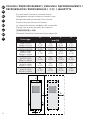
COOLING / REFROIDISSEMENT / KÜHLUNG / RAFFREDDAMENTO /
REFRIGERACIÓN / REFRIGERAÇÃO / 冷却 / JÄÄHDYTYS
The minimum clearance around the drive
Dégagement minimal autour du convertisseur
Mindestabstand um den Umrichter herum
Distanza minima intorno all’inverter
La separación mínima alrededor del convertidor
Espaço livre mínimo ao redor do conversor
变频器周围的最小间隙
Vähimmäisilmavälit taajuusmuuttajan ympärillä
Drive type
A B C D
mm (in)
0003 2-0012
20003 5-0012 5
20
(0.79)
20
(0.79)
100
(3.94)
50
(1.97)
0017 2-0031
20016 5-0031 5
20
(0.79)
20
(0.79)
120
(4.72)
60
(2.36)
0048 2-0061
20038 5-0061
50004 6-0034 6
30
(1.18)
20
(0.79)
160
(6.30)
80
(3.15)
0075 2-0114
20072 5-0105
50041 6-0052 6
80
(3.15)
80
(3.15)
300
(11.81)
100
(3.94)
0140 2-0205
20140 5-0205
50062 6-0100 6
80
(3.15)
80
(3.15)
300
(11.81)
200
(7.87)
0261 2-0300
20261 5-0300
50125 6-0208 6
50
(1.97)
80
(3.15)
400
(15.75)
250
(9.84)
A
A
2
D
A
A
2
B B
C
EN
FR
DE
IT
ES
PT-
BR
ZH
FI

5
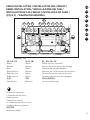
CABLE INSTALLATION / INSTALLATION DES CÂBLES /
KABELINSTALLATION / INSTALLAZIONE DEI CAVI /
INSTALACIÓN DE LOS CABLES / INSTALAÇÃO DO CABO /
电缆安装 / KAAPELIEN ASENNUS
LI, L2, L3
Mains
Réseau
Netz
Rete elettrica
Red eléctrica
Rede elétrica
电源
Verkkovirta
U, V, W
Motor
Moteur
Motor
Motore
Motor
Motor
电机
Moottori
B-, B+, R-, R-
Brake resistor terminals
Bornes de la résistance de freinage
Bremswiderstandsklemmen
Morsetti per la Resistenza di frenatura
Terminales de resistencia de freno
Terminais do resistor de frenagem
制动电阻器端子
Jarruvastuskaapelit
The earth conductor
Le conducteur de terre
Erdungsleiter
Conduttore di terra
El conductor de toma a tierra
Condutor de aterramento
接地导线
Maadoitusjohdin
L1 L2 L3 B- R+
B+
R- U V W
Example: FR6
EN
FR
DE
IT
ES
PT-
BR
ZH
FI

6
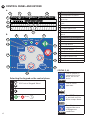
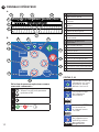
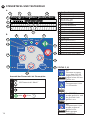
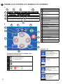
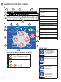
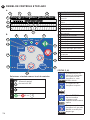
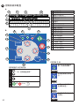
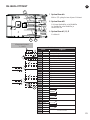
CONTROL PANEL AND KEYPAD
Selecting the keypad as the control place:
1. ‘M3 Control Keypad Menu’
2.
3.
or 3 sec
A The text display
1 The indicators of status
2
The indicators of the rotation
direction
3
The indicators of alarm and
fault
4 The location indication
5 The description line
6 The value line
7
The indicators of the control
place
B The buttons of the keypad
8 The status LEDs
9 The Start button
10 The Stop button
11 The Menu button Right
12 The Enter button
13 The Browser button Down
14 The Select button
15 The Menu button Left
16 The Reset button
17 The Browser button Up
EN
STATUS (1, 8)
ready
READY
The AC power is
connected to the
drive, no active
faults.
run
RUN
The AC drive
operates.
run
RUN
The STOP button
is pushed and the
drive ramps down.
fault
FAULT
The AC drive is
stopped because
of dangerous
conditions.
A.
B.
1
4
5
6
2 1
7
3
READY
FAULTSTOP
RUN
Bus/CommKeypadI/O term
ALARM
reset
ready
run
fault
select enter
8 8 8
9
10
11
12
13
14
15
16
17

7
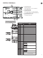
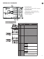
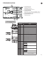
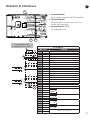
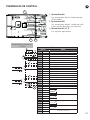
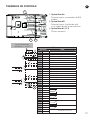
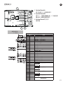
CONTROL TERMINALS
EN
1 Option Board A
The terminals for the standard
I/O connections
2
Option Board B
The terminals for 2 relay outputs
or 2 relay outputs and a thermistor
3 Option Board C, D, E
The option boards
Standard I/O
Terminal Signal
1 +10 Vref Reference voltage
2 AI1+ Analogue input, voltage or current
3 GND/AI1- Analogue input common
4 AI2+ Analogue input, voltage or current
5 GND/AI2- Analogue input common
6 24 Vout 24V aux. voltage
7 GND I/O ground
8 DI1 Digital input 1
9 DI2 Digital input 2
10 DI3 Digital input 3
11 CMA Common A for DIN1-DIN3
12 24 Vout Control voltage output
13 GND I/O ground
14 DI4 Digital input 4
15 DI5 Digital input 5
16 DI6 Digital input 6
17 CMB Common B for DIN4-DIN6
18 AO1+ Analogue signal (output)
19 AO-/GND Analogue output common
20 +24 Vin Open collector output
21 RO1/1 Relay output 1
22 RO1/2
23 RO1/3
24 RO2/1 Relay output 2
25 RO2/2
26 RO2/3
21 RO1/1 Relay output 1
22 RO1/2
23 RO1/3
24 RO2/1 Relay output 2
25 RO2/2
28 TI1+
Thermistor input
29 TI1-
Reference potentiometer
1...10 k
3
21

8
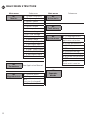
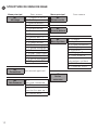
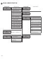
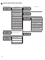
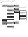
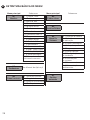
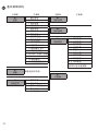
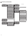
BASIC MENU STRUCTURE
EN
Main menu Submenus
M1
Monitor
V1.1 Output frequency
V1.2 Frequency ref.
V1.3 Motor speed
V1.4 Motor current
V1.5 Motor torque
V1.6 Motor power
V1.7 Motor voltage
V1.8 DC-link voltage
V1.9 Unit temperature
V1.10 Motor temp.
V1.11 Analogue Input 1
V1.12 Analogue Input 2
V1.13 Current input
V1.14 DIN1, DIN2, DIN3
V1.15 DIN4, DIN5, DIN6
V1.16 Analogue output
V1.17 Multimonit. items
M2
Parameters
See Application Manual
M3
Keypad control
P3.1 Control place
R3.2 Keypad reference
P3.3
Direction (on keypad)
P3.4 Stop button
Main menu Submenus
M4
Active faults
M5
Fault history
M6
System menu
S6.1 Language select.
S6.2
Application selection
S6.3 Copy parameters
S6.4 Compare param.
S6.5 Security
S6.6 Keypad settings
S6.7 Hardware settings
S6.8 System information
S6.9 Power monitor
S6.11
Power multi-monitor
M7
Expander
boards

9
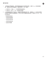
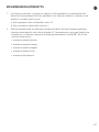
FIRST START-UP
EN
1. If the start-up wizard is active, select the language of the control panel and the
application. Accept the selections with the Enter button. If the start-up wizard is not
active, obey the instructions a and b.
a Select the language of the control panel from the Menu M6, page 6.1.
b Select the application from the Menu M6, page 6.2.
2. All parameters have factory default values. To make sure that the AC drive operates
correctly, make sure that these group G2.1 parameters have the same data as the
nameplate. For more information on the parameters in the list, see the VACON
®
All in
One Application Manual.
• Nominal voltage of the motor
• Nominal frequency of the motor
• Nominal speed of the motor
• Nominal current of the motor
• Motor cos phi

10
PANNEAU OPÉRATEUR
FR
Sélection du panneau opérateur comme
source de commande :
1.
‘Menu Contrôle du panneau
opérateur M3’
2.
3.
ou 3 sec
A L'affichage textuel
1 Indicateurs d'état
2
Indicateurs du sens de
rotation
3
Indicateurs d'alarme et de
défaut
4 Indication de position
5 Ligne de description
6 Ligne de valeur
7
Indicateurs de la source de
commande
B
Boutons du panneau
opérateur
8 Les voyants d’état
9 Touche marche
10 Touche arrêt
11 Touche de menu droite
12 Touche enter
13 Touche de navigation bas
14 La touche select (sélection)
15 Touche de menu gauche
16 La touche reset (réarmement)
17 Touche de navigation haut
STATUS (1, 8)
ready
READY
Le convertisseur de
fréquence est sous
tension et aucun
défaut n’est actif.
run
RUN
Le convertisseur
de fréquence
fonctionne.
run
RUN
La touche ARRÊT
est pressée et
le convertisseur
s’arrête.
fault
FAULT
Le convertisseur
de fréquence est
arrêté en raison
de conditions
dangereuses.
A.
B.
1
4
5
6
2 1
7
3
READY
FAULTSTOP
RUN
Bus/CommKeypadI/O term
ALARM
reset
ready
run
fault
select enter
8 8 8
9
10
11
12
13
14
15
16
17

11
BORNES DE COMMANDE
FR
1 Option Board A
Bornes de connexion d’E/S standard
2
Option Board B
Bornes des 2 sorties relais ou 2
sorties relais et une thermistance
3 Option Board C, D, E
Cartes en option
Potentiomètre de référence,
1...10 k
3
21
E/S de base
Borne Signal
1 +10 Vref Tension référence
2 AI1+ Entrée analog. en tension ou courant
3 GND/AI1- Entrée analog. comm.
4 AI2+ Entrée analog. en tension ou courant
5 GND/AI2- Entrée analog. comm.
6 24 Vout 24 V tension aux.
7 GND Terre E/S
8 DI1 Entrée logique 1
9 DI2 Entrée logique 2
10 DI3 Entrée logique 3
11 CMA A commun pour DIN1-DIN3
12 24 Vout Sortie tension commde
13 GND Terre E/S
14 DI4 Entrée logique 4
15 DI5 Entrée logique 5
16 DI6 Entrée logique 6
17 CMB B commun pour DIN4-DIN6
18 AO1+ Signal analogique (sortie +)
19 AO-/GND Commun sortie analogique
20 +24 Vin Sortie à collecteur ouvert
21 RO1/1 Sortie relais 1
22 RO1/2
23 RO1/3
24 RO2/1 Sortie relais 2
25 RO2/2
26 RO2/3
21 RO1/1 Sortie relais 1
22 RO1/2
23 RO1/3
24 RO2/1 Sortie relais 2
25 RO2/2
28 TI1+
Entrée thermistance
29 TI1-

12
STRUCTURE DE MENU DE BASE
FR
Menu principal Sous-menus
M1
Affichage
V1.1 Fréquence moteur
V1.2 Ref.Fréq.
V1.3 Vitesse moteur
V1.4 Courant moteur
V1.5 Couple moteur
V1.6 Puissance moteur
V1.7 Tension moteur
V1.8 Tension bus c.c.
V1.9 Température
V1.10 Temp. moteur
V1.11 Entrée analogique 1
V1.12 Entrée analogique 2
V1.13 Entrée courant
V1.14 DIN1, DIN2, DIN3
V1.15 DIN4, DIN5, DIN6
V1.16 Sortie analogique
V1.17 Page Multi-Aff.
M2
Paramètres
Voir manuel applicatif
M3
Cde Panneau
P3.1
Source de commande
R3.2 Réf. panneau op.
P3.3
Direction (sur pan. op.)
R3.4 Touche Arrêt
Menu principal Sous-menus
M4
Défauts actifs
M5
Historiq défauts
M6
Menu Système
S6.1 Langue
S6.2 Application
S6.3 Copie paramètres
S6.4 Compar. param.
S6.5 Sécurité
S6.6 Réglages Panneau
S6.7 Infos matériel
S6.8
Informations système
S6.9 Aff. Puissance
S6.11 MultiAff. Puiss.
M7
Cartes
extension

13
PREMIÈRE MISE EN SERVICE
FR
1. Si l’assistant de démarrage est actif, sélectionnez la langue du panneau de commande
et l’applicatif. Acceptez les sélections à l’aide de la touche Enter. Si l’assistant de
démarrage n’est pas actif, suivez les instructions a et b.
a Sélectionnez la langue du panneau de commande dans le menu M6, à la page 6.1.
b Sélectionnez l’applicatif dans le menu M6, à la page 6.2.
2. Tous les paramètres sont dotés de valeurs de préréglage usine. Pour garantir le bon
fonctionnement du variateur de fréquence, veillez à ce que les paramètres du groupe
G2.1 aient les valeurs indiquées sur la plaque signalétique. Pour plus d’informations
sur les paramètres de la liste, reportez-vous au manuel de l’applicatif « All in One »
VACON
®
.
• Nominal voltage of the motor (Tension nominale du moteur)
• Nominal frequency of the motor (Fréquence nominale du moteur)
• Nominal speed of the motor (Vitesse nominale du moteur)
• Nominal current of the motor (Courant nominal du moteur)
• Cosphi MoteurMotor cos phi

14
STEUERTAFEL UND TASTENFELD
DE
Auswahl der Steuertafel als Steuerplatz:
1. „M3 Steuertafel-Menü“
2.
3.
oder 3 sec
A Das Text-Display
1 Die Statusanzeigen
2 Die Drehrichtungsanzeigen
3
Die Alarm- und
Fehleranzeigen
4 Positionsangabe
5 Beschreibungszeile
6 Wertzeile
7 Die Steuerplatzanzeigen
B Die Tasten des Tastenfelds
8 Die Status-LEDs
9 Starttaste
10 Stopptaste
11 Menütaste (rechts)
12 Enter-Taste
13 Browsertaste (nach unten)
14 Select-Taste
15 Menütaste (links)
16 Reset-Taste
17 Browsertaste (nach oben)
STATUS (1, 8)
ready
READY
Die
Stromversorgung
ist an den Antrieb
angeschlossen, es
liegen keine aktiven
Fehler vor.
run
RUN
Der
Frequenzumrichter
ist in Betrieb.
run
RUN
Die STOPP-Taste
wurde gedrückt und
der Antrieb läuft
geführt aus.
fault
FAULT
Der
Frequenzumrichter
wurde aufgrund
gefährlicher
Bedingungen
angehalten.
A.
B.
1
4
5
6
2 1
7
3
READY
FAULTSTOP
RUN
Bus/CommKeypadI/O term
ALARM
reset
ready
run
fault
select enter
8 8 8
9
10
11
12
13
14
15
16
17

15
STEUERANSCHLÜSSE
DE
1 Option Board A
Klemmen für die
E/AStandardanschlüsse
2
Option Board B
Klemmen für 2 Relaisausgänge oder 2
Relaisausgänge und einen Thermistor
3 Option Board C, D, E
Optionskarten
Sollwertpotentiometer
1...10 k
3
21
Standard-E/A
Klemme Signal
1 +10 Vref Referenzspannung
2 AI1+ Analogeingang, Spann. bzw. Strom
3 GND/AI1- Masseansch.Sollw. u. Steuersign.
4 AI2+ Analogeingang, Spann. bzw. Strom
5 GND/AI2- Masseansch.Sollw. u. Steuersign.
6 24 Vout 24 V Hilfsspannung
7 GND E/A Masse
8 DI1 Digital Eingänge 1
9 DI2 Digital Eingänge 2
10 DI3 Digital Eingänge 3
11 CMA Gem. A für DIN1 – DIN3
12 24 Vout Steuerspannungsausgang
13 GND E/A Masse
14 DI4 Digital Eingänge 4
15 DI5 Digital Eingänge 5
16 DI6 Digital Eingänge 6
17 CMB Gemeins. B für DIN4 – DIN6
18 AO1+ Analogsignal (+-Ausgang)
19 AO-/GND An.ausg., gem.Bezpkt.
20 +24 Vin Ausgang mit offenem Kollektor
21 RO1/1 Relaisausg. 1
22 RO1/2
23 RO1/3
24 RO2/1 Relaisausg. 2
25 RO2/2
26 RO2/3
21 RO1/1 Relaisausg. 1
22 RO1/2
23 RO1/3
24 RO2/1 Relaisausg. 2
25 RO2/2
28 TI1+
Thermistoreingang
29 TI1-

16
BASISMENÜSTRUKTUR
DE
Hauptmenü Untermenüs
M1
Betriebsdaten
V1.1 Ausgangsfrequenz
V1.2 FreqReference
V1.3 Motordrehzahl
V1.4 Motorstrom
V1.5 Motordrehmoment
V1.6 Motorleistung
V1.7 Motorspannung
V1.8 DC-Spannung
V1.9 Gerätetemperatur
V1.10 Motortemp.
V1.11 Analogeingang 1
V1.12 Analogeingang 2
V1.13 Stromeingang
V1.14 DIN1, DIN2, DIN3
V1.15 DIN4, DIN5, DIN6
V1.16 Analogausgang
V1.17 Multim.-Elem.
M2
Parameter
S. Applik.-Handbuch
M3
St.ü. Steuertafel
P3.1 Steuerplatz
R3.2 Steuertafelsollwert
P3.3 Drehrichtung (über
Steuertafel)
R3.4 Stopptaste
Hauptmenü Untermenüs
M4
Active Fehler
M5
Fehlerspeicher
M6
Systemmenü
S6.1 Sprachenauswahl
S6.2 Applikationswahl
S6.3
Parameterübertragung
S6.4 Parameter vergl.
S6.5 Sicherheit
S6.6 StTafEinstellung
S6.7 Hardware-Einst.
S6.8
Systeminformationen
S6.9 Power monitor
S6.11
Leist.-Multimonitor
M7
Zusatzungen

17
ERSTES ANLAUFEN
DE
1. Wenn der Inbetriebnahmeassistent aktiviert ist, wählen Sie die Sprache für die
Bedieneinheit und Applikation aus. Bestätigen Sie die Auswahl mit der Enter-Taste.
Wenn der Inbetriebnahmeassistent nicht aktiviert ist, befolgen Sie die Anweisungen
a und b.
a Wählen Sie im Menü M6 auf Seite 6.1 die Sprache für die Bedieneinheit aus.
b Wählen Sie im Menü M6 auf Seite 6.2 die Applikation aus.
2. Alle Parameter sind werkseitig voreingestellt. Damit die Frequenzumrichter
reibungslos funktionieren, müssen die Gruppenparameter G2.1 dieselben Daten
aufweisen wie das Typenschild. Weitere Informationen zu Parametern in der Liste
finden Sie im VACON
®
All-in-One-Applikationshandbuch.
• Nennspannung des Motors
• Nennfrequenz des Motors
• Nenndrehzahl des Motors
• Nennstrom des Motors
• cos phi, Motor

18
PANNELLO DI CONTROLLO E PANNELLO DI COMANDO
IT
Selezione del pannello di comando come
postazione di controllo:
1.
‘Menu del pannello
di comando M3’
2.
3.
o 3 sec
A Il display di testo
1 Gli indicatori di stato
2
Gli indicatori della direzione
di rotazione
3
Gli indicatori di allarme
e guasto
4 Indicazione di posizione
5 Riga descrittiva
6 Riga dei valori
7
Gli indicatori della postazione
di controllo
B
Pulsanti del pannello di
comando
8 LED di stato
9 Pulsante di avvio
10 Pulsante di arresto
11 Pulsante menu a destra
12 Pulsante ENTER
13 Pulsante freccia giù
14 Pulsante SELECT
15 Pulsante menu a sinistra
16 Pulsante RESET
17 Pulsante freccia su
STATUS (1, 8)
ready
READY
La corrente
CA è collegata
all’inverter, nessun
guasto attivo.
run
RUN
L’inverter è pronto
all’uso.
run
RUN
Il pulsante di
ARRESTO viene
premuto
e l’inverter rallenta.
fault
FAULT
L’inverter viene
arrestato a causa
di condizioni
pericolose.
A.
B.
1
4
5
6
2 1
7
3
READY
FAULTSTOP
RUN
Bus/CommKeypadI/O term
ALARM
reset
ready
run
fault
select enter
8 8 8
9
10
11
12
13
14
15
16
17

19
MORSETTI DI CONTROLLO
IT
1 Option Board A
Morsetti per connessioni I/O standard
2
Option Board B
Morsetti per 2 uscite relè o 2 uscite
relè e un termistore
3 Option Board C, D, E
Schede opzionali
Potenziometro di
riferimento, 1...10 k
3
21
I/O standard
Morsetto Segnale
1 +10 Vref Tensione di riferimento
2 AI1+ Ingresso analogico, in tensione o corrente
3 GND/AI1- Ingresso analogico comune
4 AI2+ Ingresso analogico, in tensione o corrente
5 GND/AI2- Ingresso analogico comune
6 24 Vout Tensione 24 V aus.
7 GND Massa I/O
8 DI1 Ingresso digitale 1
9 DI2 Ingresso digitale 2
10 DI3 Ingresso digitale 3
11 CMA Comune A per DIN1-DIN3
12 24 Vout Uscita tensione di controllo
13 GND Massa I/O
14 DI4 Ingresso digitale 4
15 DI5 Ingresso digitale 5
16 DI6 Ingresso digitale 6
17 CMB Comune B per DIN4-DIN6
18 AO1+ Segnale uscita analogica (+)
19 AO-/GND Comune uscita analogica
20 +24 Vin Usc. collett. aperto
21 RO1/1 Uscita relè 1
22 RO1/2
23 RO1/3
24 RO2/1 Uscita relè 2
25 RO2/2
26 RO2/3
21 RO1/1 Uscita relè 1
22 RO1/2
23 RO1/3
24 RO2/1 Uscita relè 2
25 RO2/2
28 TI1+
Ingresso termistore
29 TI1-

20
STRUTTURA DI BASE DEI MENU
IT
Menu principale Sottomenu
M1
Monitor
V1.1 Frequenza uscita
V1.2 RifFrequenza
V1.3 Velocità motore
V1.4 Corrente motore
V1.5 Coppia motore
V1.6 Potenza motore
V1.7 Tensione motore
V1.8 Tensione DC-Link
V1.9 Temperat. unità
V1.10 Temp. motore
V1.11 IngressoAnalog 1
V1.12 IngressoAnalog 2
V1.13 IngressoCorrente
V1.14 DIN1, DIN2, DIN3
V1.15 DIN4, DIN5, DIN6
V1.16 Uscita analogica
V1.17 Valori multimon.
M2
Parametri
Vedere man. applic.
M3
Pannello di
comando
P3.1 Post. contr.
R3.2 Rifer. pannello
P3.3
Direzione (su pannell o)
R3.4 Pulsante Arresto
Menu principale Sottomenu
M4
Guasti attivi
M5
Memoria guasti
M6
Menù di sistema
S6.1 Scelta della lingua
S6.2 Scelta applicazione
S6.3 Copia parametri
S6.4 Confronto param.
S6.5 Sicurezza
S6.6 ImpostazPannello
S6.7 Impostaz. hardware
S6.8 Informazioni
S6.9 Monitor potenza
S6.11 Multimon potenza
M7
E spansioni
La pagina si sta caricando...
La pagina si sta caricando...
La pagina si sta caricando...
La pagina si sta caricando...
La pagina si sta caricando...
La pagina si sta caricando...
La pagina si sta caricando...
La pagina si sta caricando...
La pagina si sta caricando...
La pagina si sta caricando...
La pagina si sta caricando...
La pagina si sta caricando...
La pagina si sta caricando...
La pagina si sta caricando...
La pagina si sta caricando...
La pagina si sta caricando...
La pagina si sta caricando...
La pagina si sta caricando...
La pagina si sta caricando...
La pagina si sta caricando...
-
 1
1
-
 2
2
-
 3
3
-
 4
4
-
 5
5
-
 6
6
-
 7
7
-
 8
8
-
 9
9
-
 10
10
-
 11
11
-
 12
12
-
 13
13
-
 14
14
-
 15
15
-
 16
16
-
 17
17
-
 18
18
-
 19
19
-
 20
20
-
 21
21
-
 22
22
-
 23
23
-
 24
24
-
 25
25
-
 26
26
-
 27
27
-
 28
28
-
 29
29
-
 30
30
-
 31
31
-
 32
32
-
 33
33
-
 34
34
-
 35
35
-
 36
36
-
 37
37
-
 38
38
-
 39
39
-
 40
40


