Garmin Reactor™ 40 Steer-by-wire Corepack for Volvo-Penta® without GHC™ 20 Istruzioni per l'uso
- Tipo
- Istruzioni per l'uso

GHP
®
Reactor™ Steer-by-Wire Volvo
®
Gateway Addendum
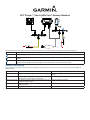
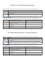
When installing the Garmin autopilot on your boat, refer to this diagram to connect the autopilot to the steering system through this gateway.
Item Description
➊
Autopilot gateway. This connects to the steering system of your boat.
➋
Gateway data bus. The included T-connectors must be assembled as shown to properly communicate with the autopilot
gateway.
➌
The included power cable must be connected to a 9–24 Vdc power source for the autopilot to communicate with the gateway.
When the Autopilot LED
➊
on the gateway adapter is solid, the data bus is correctly connected to power.
Gateway Troubleshooting
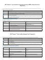
If the autopilot does not appear to be correctly communicating with the steering system of the boat, you should observe the Diagnostic LED ➋ on the
gateway adapter.
LED Behavior Description Troubleshooting
Off The gateway is not receiving power from the steering system. The gateway may not be connected correctly to the steering
system.
Solid The gateway is receiving power from the steering system, but
is not receiving communication from either side.
Check all connections.
Flashing double-blink The gateway is receiving data from the steering system, but
not from the autopilot system.
Check all autopilot connections.
Flashing triple-blink The gateway is receiving data from the autopilot, but not from
the steering system.
Check all steering-system connections.
Flashing The gateway is properly receiving and transmitting data.
La pagina si sta caricando...

GHP
®
Reactor™-Steer-by-Wire-Volvo
®
-Gateway – Nachtrag
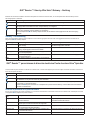
Beziehen Sie sich bei der Installation des Garmin-Autopiloten auf dem Boot auf diesen Plan, um den Autopiloten über dieses Gateway mit dem
Steuerungssystem zu verbinden.
Element Beschreibung
➊
Autopilot-Gateway. Hiermit wird die Verbindung mit dem Steuerungssystem des Boots hergestellt.
➋
Datenbus des Gateways. Die mitgelieferten T-Stücke müssen wie abgebildet zusammengesetzt werden, um eine
ordnungsgemäße Kommunikation mit dem Autopilot-Gateway zu ermöglichen.
➌
Das mitgelieferte Netzkabel muss mit einer Gleichstromquelle von 9 bis 24 V verbunden werden, um die Kommunikation
zwischen dem Autopiloten und dem Gateway zu ermöglichen.
Wenn die Autopilot-LED
➊
am Gateway-Adapter leuchtet, ist der Datenbus ordnungsgemäß mit der Stromversorgung
verbunden.
Gateway – Fehlerbehebung
Wenn die Kommunikation zwischen dem Autopiloten und dem Steuerungssystem des Boots nicht ordnungsgemäß funktioniert, beachten Sie die
Diagnose-LED
➋ am Gateway-Adapter.
LED-Anzeige Beschreibung Fehlerbehebung
Aus Das Gateway wird nicht über das Steuerungssystem mit
Strom versorgt.
Das Gateway ist möglicherweise nicht ordnungsgemäß mit
dem Steuerungssystem verbunden.
Leuchtet Das Gateway wird über das Steuerungssystem mit Strom
versorgt, empfängt jedoch keine Kommunikation.
Überprüfen Sie alle Anschlüsse.
Blinkt doppelt Das Gateway empfängt Daten vom Steuerungssystem, aber
nicht vom Autopilotsystem.
Überprüfen Sie alle Anschlüsse zum Autopiloten.
Blinkt dreifach Das Gateway empfängt Daten vom Autopiloten, aber nicht
vom Steuerungssystem.
Überprüfen Sie alle Anschlüsse zum Steuerungssystem.
Blinkt Das Gateway empfängt und sendet Daten ordnungsgemäß.
GHP
®
Reactor™ para sistemas de dirección electrónica Puerta de enlace Volvo
®
Apéndice
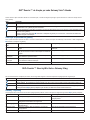
Cuando instales el piloto automático de Garmin en la embarcación, consulta este diagrama para conectar el piloto automático al sistema de dirección a
través de esta puerta de enlace.
Elemento Descripción
➊
Puerta de enlace del piloto automático. Se conecta al sistema de dirección de la embarcación.
➋
Bus de datos de la puerta de enlace. Los conectores en T incluidos deben montarse como se muestra para comunicarse
adecuadamente con la puerta de enlace del piloto automático.
➌
El cable de alimentación incluido debe conectarse a una fuente de alimentación de 9–24 V de CC para que el piloto automático
se comunique con la puerta de enlace.
Cuando el LED
➊
del piloto automático en el adaptador de la puerta de enlace esté jo, el bus de datos está correctamente
conectado a la alimentación.
Solución de problemas de la puerta de enlace
En caso de que parezca que el piloto automático no se comunica correctamente con el sistema de dirección de la embarcación, debes jarte en el LED
de diagnóstico
➋ del adaptador de puerta de enlace.
Funcionamiento del
LED
Descripción Solución de problemas
Apagado La puerta de enlace no recibe correctamente alimentación del
sistema de dirección.
Es posible que la puerta de enlace no esté correctamente
conectada al sistema de dirección.
Fijo La puerta de enlace recibe alimentación del sistema de
dirección pero no recibe comunicación de ningún lado.
Comprueba todas las conexiones.
Parpadeo doble La puerta de enlace recibe datos del sistema de dirección
pero no del sistema de piloto automático.
Comprueba todas las conexiones del piloto automático.
Parpadeo triple La puerta de enlace recibe datos del piloto automático pero
no del sistema de dirección.
Comprueba todas las conexiones del sistema de dirección.
Parpadeo La puerta de enlace recibe y transmite datos correctamente.
La pagina si sta caricando...
La pagina si sta caricando...

© 2014 Garmin Ltd. or its subsidiaries
Garmin International, Inc.
1200 East 151
st
Street, Olathe, Kansas 66062, USA
Garmin (Europe) Ltd.
Liberty House, Hounsdown Business Park, Southampton, Hampshire, SO40 9LR UK
Garmin Corporation
No. 68, Zhangshu 2
nd
Road, Xizhi Dist., New Taipei City, 221, Taiwan (R.O.C.)
www.garmin.com
December 2014 Printed in Taiwan 190-01766-90_0A
-
 1
1
-
 2
2
-
 3
3
-
 4
4
-
 5
5
-
 6
6


Garmin Reactor™ 40 Steer-by-wire Corepack for Volvo-Penta® without GHC™ 20 Istruzioni per l'uso
- Tipo
- Istruzioni per l'uso
in altre lingue
- English: Garmin Reactor™ 40 Steer-by-wire Corepack for Volvo-Penta® without GHC™ 20 Operating instructions
- français: Garmin Reactor™ 40 Steer-by-wire Corepack for Volvo-Penta® without GHC™ 20 Mode d'emploi
- español: Garmin Reactor™ 40 Steer-by-wire Corepack for Volvo-Penta® without GHC™ 20 Instrucciones de operación
- Deutsch: Garmin Reactor™ 40 Steer-by-wire Corepack for Volvo-Penta® without GHC™ 20 Bedienungsanleitung
- português: Garmin Reactor™ 40 Steer-by-wire Corepack for Volvo-Penta® without GHC™ 20 Instruções de operação
- dansk: Garmin Reactor™ 40 Steer-by-wire Corepack for Volvo-Penta® without GHC™ 20 Betjeningsvejledning
- svenska: Garmin Reactor™ 40 Steer-by-wire Corepack for Volvo-Penta® without GHC™ 20 Bruksanvisningar
Documenti correlati
-
Garmin Reactor™ 40 Steer-by-wire Corepack for Yamaha® Helm Master® with GHC 20 Istruzioni per l'uso
-
Garmin GRF 10 Rorfeedback-sensor Guida d'installazione
-
Garmin GPSMAP 86s Product notices
-
Garmin Piloto automatico eyector Reactor 40 Guida d'installazione
-
