
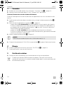
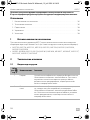
MCR7
Remote control
Operating manual. . . . . . . . . . . . . . . . . . . . 3
Fernbedienung
Bedienungsanleitung . . . . . . . . . . . . . . . . . 6
Télécommande
Notice d’utilisation . . . . . . . . . . . . . . . . . . . 9
Control remoto
Instrucciones de uso . . . . . . . . . . . . . . . . . 12
Controlo remoto
Manual de instruções . . . . . . . . . . . . . . . . 15
Comando a distanza
Istruzioni per l’uso. . . . . . . . . . . . . . . . . . . 18
Afstandsbediening
Gebruiksaanwijzing . . . . . . . . . . . . . . . . . 21
Fjernbetjening
Betjeningsvejledning . . . . . . . . . . . . . . . . 24
Fjärrkontroll
Bruksanvisning . . . . . . . . . . . . . . . . . . . . . 27
Fjernkontroll
Bruksanvisning . . . . . . . . . . . . . . . . . . . . . 30
Kaukosäädin
Käyttöohje. . . . . . . . . . . . . . . . . . . . . . . . . 33
Пульт дистанционного
управления
Инструкция по эксплуатации . . . . . . . . . 36
Pilot
Instrukcja obsługi . . . . . . . . . . . . . . . . . . . 39
Diaľkové ovládanie
Návod na obsluhu . . . . . . . . . . . . . . . . . . 45
Dálkový ovladač
Návod k obsluze. . . . . . . . . . . . . . . . . . . . 42
Tá vi r á ny ít ó
Használati utasítás . . . . . . . . . . . . . . . . . . 48
Battery Output (%)
15
14
13
12
11
10
OVP
UVP
OTP
OLP
100
80
60
40
20
INV.
GRID
PWR.
SAV.
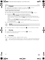
Remote Control
ON/OFF
Volts
Power
SinePower Accessory
EN
DE
FR
ES
PT
IT
NL
DA
SV
NO
FI
RU
PL
SK
CS
HU
ENERGY & LIGHTING
SINEPOWER
MCR7-O-16s.book Seite 1 Mittwoch, 13. Juli 2016 4:58 16

MCR7
2
1
Battery Output (%)
15
14
13
12
11
10
OVP
UVP
OTP
OLP
100
80
60
40
20
INV.
GRID
PWR.
SAV.
Remote Control
ON/OFF
Volts
Power
SinePower Accessory
5
3
4
1
2
2
1
34
A
B
2
MCR7-O-16s.book Seite 2 Mittwoch, 13. Juli 2016 4:58 16

MCR7 Intended use
EN
3
Please read this instruction manual carefully before first use, and store it in a safe place.
If you pass on the product to another person, hand over this instruction manual along
with it.
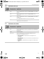
Contents
1 Intended use . . . . . . . . . . . . . . . . . . . . . . . . . . . . . . . . . . . . . . . . . . . . . . . . . . . . . . . . . . . . . . . 3
2 Technical description . . . . . . . . . . . . . . . . . . . . . . . . . . . . . . . . . . . . . . . . . . . . . . . . . . . . . . . . 3
3 Connection . . . . . . . . . . . . . . . . . . . . . . . . . . . . . . . . . . . . . . . . . . . . . . . . . . . . . . . . . . . . . . . . 5
4 Service. . . . . . . . . . . . . . . . . . . . . . . . . . . . . . . . . . . . . . . . . . . . . . . . . . . . . . . . . . . . . . . . . . . .5
5 Disposal. . . . . . . . . . . . . . . . . . . . . . . . . . . . . . . . . . . . . . . . . . . . . . . . . . . . . . . . . . . . . . . . . . . 5
1Intended use
The MCR7 remote control is suitable for switching on/off the following inverters via the “remote
port II” (see also the operating manual for the inverter):
• MSP702, MSP704, MSP1012, MSP1014, MSP1512, MSP1524, MSP2012, MSP2024,
MSP2512, MSP2524
• MSI912, MSI 924, MSI1312, MSI 1324, MSI1812, MSI1824, MSI1812T, MSI 1824T, MSI2312T,
MSI2324T, MSI3512T, MSI3524T
2 Technical description
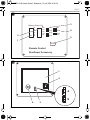
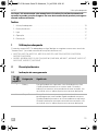
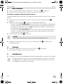
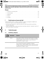
2.1 Power display
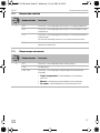
No. in
fig. 1,
page 2
Description Meaning
1 Battery This bar graph shows the battery voltage in volts.
The display should be in the green area. If the display is above
or below in the red area, a warning tone sounds, the display
flashes and the inverter will be switched off.
2 Output Power This bar graph displays the output power received by the
appliance as a percentage.
The display should be in the green or orange area. If the display
goes over into the red area, a warning tone sounds, the display
flashes and the inverter will be shut off.
MCR7-O-16s.book Seite 3 Mittwoch, 13. Juli 2016 4:58 16

Technical description MCR7
EN
4
2.2 Error displays
2.3 Status displays
No. in
fig. 1,
page 2
Description Meaning
3 OVP This LED shows that the inverter is switching off due to
overvoltage.
UVP This LED shows that the inverter is switching off due to low
voltage.
OTP This LED shows that the inverter is switching off due to
overheating.
This LED switches off when the inverter has cooled down.
OLP This LED shows that the inverter is switching off due overloading
or short-circuiting.
No. in
fig. 1,
page 2
Description Meaning
4 INV This LED shows that the inverter is in standby mode.
GRID No function
PWR SAV. This LED shows whether the inverter's energy saving mode
(standby) is activated.
• Constant glow: The energy saving mode is switched on.
• Flashing: The inverter is in energy saving mode.
• Off: The energy saving mode is switched off.
MCR7-O-16s.book Seite 4 Mittwoch, 13. Juli 2016 4:58 16

MCR7 Connection
EN
5
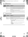
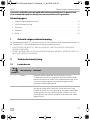
3 Connection
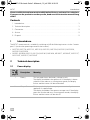
➤ Insert one side of the RJ-11 cable in the socket “To inverter” (fig. 2 2, page 2).
➤ Insert the other side of the RJ-11 cable into the “Remote Port II” of the inverter.
Switching on/off by external signal
The remote control enables the optional switching on/off of the inverter by external signal:
➤ Loosen both Phillips screws and take off the cap (fig. 2 1, page 2).
➤ Set the desired connection on the jumper (fig. 2 3, page 2):
–Jumper open (A): Switching off inverter by positive battery voltage
When a plus signal is present on the control cable, the inverter is switched off (suitable e. g.
for roof air conditioners). If no signal is received, the inverter works in the previously acti-
vated function.
–Jumpers closed (B): Switching on inverter by positive battery voltage
When a plus signal is present on the control cable, the inverter is switched on and remains
on as long as the plus signal is present.
➤ Assemble the cap (fig. 2 1, page 2).
A
➤ Connect the control cable (12 V or 24 V) at the remote control connection (fig. 2 4, page 2).
4Service
➤ With the “On/Off” button (fig. 2 2page 2) switch the inverter on or off.
✓ An acoustic signal sounds.
5Disposal
➤ Place the packaging material in the appropriate recycling waste bins wherever possible.
M
If you wish to finally dispose of the product, ask your local recycling centre or specialist
dealer for details about how to do this in accordance with the applicable disposal
regulations.
NOTICE!
The control cable has to be secured by a suitable fuse (≤ 1A.)
MCR7-O-16s.book Seite 5 Mittwoch, 13. Juli 2016 4:58 16

Bestimmungsgemäßer Gebrauch MCR7
DE
6
Bitte lesen Sie diese Anleitung vor der Inbetriebnahme sorgfältig durch und bewahren
Sie sie auf. Geben Sie sie im Falle einer Weitergabe des Produktes an den Nutzer
weiter.
Inhaltsverzeichnis
1 Bestimmungsgemäßer Gebrauch . . . . . . . . . . . . . . . . . . . . . . . . . . . . . . . . . . . . . . . . . . . . . . 6
2 Technische Beschreibung . . . . . . . . . . . . . . . . . . . . . . . . . . . . . . . . . . . . . . . . . . . . . . . . . . . .6
3 Anschließen . . . . . . . . . . . . . . . . . . . . . . . . . . . . . . . . . . . . . . . . . . . . . . . . . . . . . . . . . . . . . . . 8
4 Bedienen. . . . . . . . . . . . . . . . . . . . . . . . . . . . . . . . . . . . . . . . . . . . . . . . . . . . . . . . . . . . . . . . . . 8
5 Entsorgung . . . . . . . . . . . . . . . . . . . . . . . . . . . . . . . . . . . . . . . . . . . . . . . . . . . . . . . . . . . . . . . . 8
1 Bestimmungsgemäßer Gebrauch
Die Fernbedienung MCR7 eignet sich zum Ein-/Ausschalten folgender Wechselrichter über den
„Remote Port II“ (siehe auch die Bedienungsanleitung des Wechselrichters):
• MSP702, MSP704, MSP1012, MSP1014, MSP1512, MSP1524, MSP2012, MSP2024,
MSP2512, MSP2524
• MSI912, MSI 924, MSI1312, MSI 1324, MSI1812, MSI1824, MSI1812T, MSI 1824T, MSI2312T,
MSI2324T, MSI3512T, MSI3524T
2 Technische Beschreibung
2.1 Ladeanzeigen
Nr. in
Abb. 1,
Seite 2
Bezeichnung Bedeutung
1 Battery Diese Balkenanzeige zeigt die Batteriespannung in Volt an.
Die Anzeige sollte sich im grünen Bereich befinden. Wenn sich
die Anzeige oben oder unten im roten Bereich befindet, ertönt
ein Warnton, die Anzeige blinkt und der Wechselrichter wird
abgeschaltet.
2 Output Power Diese Balkenanzeige zeigt die Ausgangsleistung in Prozent an,
die der angeschlossene Verbraucher vom Wechselrichter
erhält.
Die Anzeige sollte sich im grünen oder orangefarbenen Bereich
befinden. Wenn die Anzeige in den roten Bereich übergeht,
ertönt ein Warnton, die Anzeige blinkt und der Wechselrichter
wird abgeschaltet.
MCR7-O-16s.book Seite 6 Mittwoch, 13. Juli 2016 4:58 16

MCR7 Technische Beschreibung
DE
7
2.2 Fehleranzeigen
2.3 Statusanzeigen
Nr. in
Abb. 1,
Seite 2
Bezeichnung Bedeutung
3 OVP Diese LED zeigt an, dass der Wechselrichter wegen Über-
spannung abschaltet.
UVP Diese LED zeigt an, dass der Wechselrichter wegen Unter-
spannung abschaltet.
OTP Diese LED zeigt an, dass der Wechselrichter wegen Über-
temperatur abschaltet.
Diese LED schaltet sich aus, wenn der Wechselrichter abgekühlt
ist.
OLP Diese LED zeigt an, dass der Wechselrichter wegen Überlast
oder Kurzschluss abschaltet.
Nr. in
Abb. 1,
Seite 2
Bezeichnung Bedeutung
4 INV Diese LED zeigt an, dass sich der Wechselrichter in Bereitschaft
befindet.
GRID keine Funktion
PWR. SAV. Diese LED zeigt an, ob der Energiesparmodus (Standby) des
Wechselrichters aktiviert ist.
• Dauerlicht: Der Energiesparmodus ist eingeschaltet.
• Blinken: Der Wechselrichter befindet sich im Energie-
sparmodus.
• Aus: Der Energiesparmodus ist ausgeschaltet.
MCR7-O-16s.book Seite 7 Mittwoch, 13. Juli 2016 4:58 16

Anschließen MCR7
DE
8
3Anschließen
➤ Stecken Sie eine Seite des RJ-11-Kabels in die Buchse „To Inverter“ (Abb. 2 2, Seite 2).
➤ Stecken Sie die andere Seite des RJ-11-Kabels in den „Remote Port II“ des Wechselrichters.
Über ein externes Signal ein-/ausschalten
Die Fernbedienung ermöglicht das optionale Ein-/Ausschalten des Wechselrichters über ein
externes Signal:
➤ Lösen Sie die beiden Kreuzschlitzschrauben und nehmen Sie die Schutzkappe (Abb. 2 1,
Seite 2) ab.
➤ Stellen Sie am Jumper (Abb. 2 3, Seite 2) den gewünschten Anschluss ein:
– Jumper offen (A): Wechselrichter-Ausschaltung durch Plus-Batteriespannung
Der Wechselrichter wird ausgeschaltet, wenn an der Steuerleitung ein Plus-Signal anliegt
(geeignet z. B. für Dachklimaanlagen). Wenn kein Signal anliegt, arbeitet der Wechsel-
richter in der vorher aktivierten Funktion.
–Jumper geschlossen (B): Wechselrichter-Einschaltung durch Plus-Batteriespannung
Der Wechselrichter wird durch ein Plus-Signal an der Steuerleitung eingeschaltet und
bleibt eingeschaltet, solange das Plus-Signal anliegt.
➤ Montieren Sie die Schutzkappe (Abb. 2 1, Seite 2).
A
➤ Schließen Sie die Steuerleitung (12 V oder 24 V) am Anschluss (Abb. 2 4, Seite 2) der Fern-
bedienung an.
4Bedienen
➤ Schalten Sie den Wechselrichter mit dem Taster „On/Off“ (Abb. 2 2, Seite 2) ein oder aus.
✓ Ein akustisches Signal ertönt zur Bestätigung.
5Entsorgung
➤ Geben Sie das Verpackungsmaterial möglichst in den entsprechenden Recycling-Müll.
M
Wenn Sie das Produkt endgültig außer Betrieb nehmen, informieren Sie sich bitte beim
nächsten Recyclingcenter oder bei Ihrem Fachhändler über die zutreffenden
Entsorgungsvorschriften.
ACHTUNG!
Die Steuerleitung muss durch eine geeignete Sicherung (≤ 1 A) abgesichert sein.
MCR7-O-16s.book Seite 8 Mittwoch, 13. Juli 2016 4:58 16

MCR7 Usage conforme
FR
9
Veuillez lire ce manuel attentivement avant de mettre l'appareil en service et
conservez-le. En cas de passer le produit, veuillez le transmettre au nouvel acquéreur.
Table des matières
1 Usage conforme . . . . . . . . . . . . . . . . . . . . . . . . . . . . . . . . . . . . . . . . . . . . . . . . . . . . . . . . . . . . 9
2 Description technique . . . . . . . . . . . . . . . . . . . . . . . . . . . . . . . . . . . . . . . . . . . . . . . . . . . . . . . 9
3 Raccordement. . . . . . . . . . . . . . . . . . . . . . . . . . . . . . . . . . . . . . . . . . . . . . . . . . . . . . . . . . . . . 11
4 Utilisation. . . . . . . . . . . . . . . . . . . . . . . . . . . . . . . . . . . . . . . . . . . . . . . . . . . . . . . . . . . . . . . . . 11
5 Recyclage . . . . . . . . . . . . . . . . . . . . . . . . . . . . . . . . . . . . . . . . . . . . . . . . . . . . . . . . . . . . . . . . 11
1Usage conforme
La télécommande MCR7 convient pour la mise en marche / à l'arrêt des onduleurs suivants, via le
« Remote Port » (voir également la notice d'utilisation de l'onduleur) :
• MSP702, MSP704, MSP1012, MSP1014, MSP1512, MSP1524, MSP2012, MSP2024,
MSP2512, MSP2524
• MSI912, MSI 924, MSI1312, MSI 1324, MSI1812, MSI1824, MSI1812T, MSI 1824T, MSI2312T,
MSI2324T, MSI3512T, MSI3524T
2 Description technique
2.1 Indicateurs de charge
N° dans
fig. 1,
page 2
Désignation Signification
1 Battery Cet affichage en bâtons indique la tension de la batterie en
volts.
L'affichage doit se trouver dans la zone verte. Si l'affichage se
trouve en haut ou en bas, dans la zone rouge, un signal sonore
retentit, l'affichage clignote et l'onduleur s'éteint.
2 Output Power Cet affichage en bâtons indique la puissance de sortie en
pourcentage reçue par le consommateur raccordé.
L'affichage doit se trouver dans la zone verte ou orange. Si l'affi-
chage passe dans la zone rouge, un signal sonore retentit, l'affi-
chage clignote et l'onduleur s'éteint.
MCR7-O-16s.book Seite 9 Mittwoch, 13. Juli 2016 4:58 16

Description technique MCR7
FR
10
2.2 Affichages d'erreurs
2.3 Signalisations d'état
N° dans
fig. 1,
page 2
Désignation Signification
3 OVP Cette DEL indique que l'onduleur s'éteint en raison d'une
surtension.
UVP Cette DEL indique que l'onduleur s'éteint en raison d'une sous-
tension.
OTP Cette DEL indique que l'onduleur s'éteint en raison d'une sur-
chauffe.
Cette DEL s'éteint lorsque l'onduleur a refroidi.
OLP Cette DEL indique que l'onduleur s'éteint en raison d'une sur-
charge ou d'un court-circuit.
N° dans
fig. 1,
page 2
Désignation Signification
4 INV Cette DEL indique que l'onduleur est en mode veille.
GRID Sans fonction
PWR. SAV. Cette DEL indique que le mode d'économie d'énergie (stand
by) de l'onduleur est activé.
• Allumage continu : le mode d'économie d'énergie est
activé.
• Clignote : l'onduleur est en mode d'économie d'énergie.
• Eteint : le mode d'économie d'énergie est désactivé.
MCR7-O-16s.book Seite 10 Mittwoch, 13. Juli 2016 4:58 16

MCR7 Raccordement
FR
11
3 Raccordement
➤ Branchez une extrémité du câble RJ-11 dans la douille « To Inverter » (fig. 2 2, page 2).
➤ Branchez l'autre extrémité du câble RJ-11 dans le « Remote Port II » de l'onduleur.
Mise en marche / à l'arrêt par un signal externe
La télécommande permet d'utiliser une option de mise en marche / à l'arrêt de l'onduleur par un
signal externe
➤ Desserrez les deux vis cruciformes et retirez le capuchon de protection (fig. 2 1, page 2).
➤ Au niveau du cavalier (fig. 2 3, page 2), réglez le raccordement souhaité :
– cavalier ouvert (A) : mise à l'arrêt de l'onduleur par la tension positive de la batterie
L'onduleur est mis à l'arrêt lorsqu'un signal positif est présent sur la ligne de commande
(idéal p. ex. pour les climatiseurs de toit). Lorsqu'il n'y a aucun signal, l'onduleur fonc-
tionne selon la fonction activée précédemment.
– cavalier fermé (B) : mise en marche de l'onduleur par la tension positive de la batterie
L'onduleur est mis en marche lorsqu'un signal positif est présent sur la ligne de commande
et reste activé tant que le signal positif est présent.
➤ Montez le capuchon de protection (fig. 2 1, page 2).
A
➤ Raccordez la ligne de commande (12 V ou 24 V) au raccordement (fig. 2 4, page 2) de la
télécommande.
4 Utilisation
➤ Mettez l'onduleur en marche ou à l'arrêt en appuyant sur la touche « On/Off » (fig. 2 2,
page 2).
✓ Un signal sonore retentit pour confirmer.
5Recyclage
➤ Jetez les emballages dans les conteneurs de déchets recyclables prévus à cet effet.
M
Lorsque vous mettrez votre produit définitivement hors service, informez-vous auprès
du centre de recyclage le plus proche ou auprès de votre revendeur spécialisé sur les
prescriptions relatives au retraitement des déchets.
AVIS !
La ligne de commande doit être protégée par un fusible adapté (≤ 1A).
MCR7-O-16s.book Seite 11 Mittwoch, 13. Juli 2016 4:58 16

Uso adecuado MCR7
ES
12
Antes de poner en funcionamiento el producto, lea atentamente estas instrucciones y
consérvelas para futuras consultas. En caso de vender o entregar el producto a otra
persona, entregue también estas instrucciones.
Índice
1 Uso adecuado. . . . . . . . . . . . . . . . . . . . . . . . . . . . . . . . . . . . . . . . . . . . . . . . . . . . . . . . . . . . . 12
2 Descripción técnica . . . . . . . . . . . . . . . . . . . . . . . . . . . . . . . . . . . . . . . . . . . . . . . . . . . . . . . . 12
3 Conexión. . . . . . . . . . . . . . . . . . . . . . . . . . . . . . . . . . . . . . . . . . . . . . . . . . . . . . . . . . . . . . . . . 14
4 Manejo . . . . . . . . . . . . . . . . . . . . . . . . . . . . . . . . . . . . . . . . . . . . . . . . . . . . . . . . . . . . . . . . . . 14
5 Gestión de residuos . . . . . . . . . . . . . . . . . . . . . . . . . . . . . . . . . . . . . . . . . . . . . . . . . . . . . . . . 14
1Uso adecuado
El control remoto MCR7 es apropiado para conectar/desconectar los siguientes inversores a
través del “Remote Port II” (véanse también las instrucciones de uso del inversor):
• MSP702, MSP704, MSP1012, MSP1014, MSP1512, MSP1524, MSP2012, MSP2024,
MSP2512, MSP2524
• MSI912, MSI 924, MSI1312, MSI 1324, MSI1812, MSI1824, MSI1812T, MSI 1824T, MSI2312T,
MSI2324T, MSI3512T, MSI3524T
2 Descripción técnica
2.1 Indicadores de carga
Nº en
fig. 1,
página 2
Denominación Significado
1 Battery Este indicador de barras muestra la tensión de la batería en
voltios.
El indicador debe encontrarse dentro del rango de color
verde. Si el indicador se encuentra por encima o por debajo,
en el rango de color rojo, suena una señal acústica de adver-
tencia, el indicador parpadea y se desconecta el inversor.
2 Output Power Este indicador de barras muestra la potencia de salida en tanto
por ciento que recibe del inversor el consumidor conectado.
El indicador debe encontrarse dentro del rango de color verde
o naranja. Cuando el indicador entra en el rango de color rojo,
suena una señal acústica de advertencia, el indicador parpa-
dea y se apaga el inversor.
MCR7-O-16s.book Seite 12 Mittwoch, 13. Juli 2016 4:58 16

MCR7 Descripción técnica
ES
13
2.2 Indicadores de error
2.3 Indicadores de estado
N.º en
fig. 1,
página 2
Denominación Significado
3 OVP Este LED indica que el inversor se apaga debido a una sobre-
tensión.
UVP Este LED indica que el inversor se apaga debido a una
subtensión.
OTP Este LED indica que el inversor se apaga debido a una sobre-
temperatura.
El LED de apaga cuando el inversor se ha enfriado.
OLP Este LED indica que el inversor se apaga debido a una
sobrecarga o a un cortocircuito.
N.º en
fig. 1,
página 2
Denominación Significado
4 INV Este LED indica que el inversor se encuentra en estado de dis-
ponibilidad.
GRID No tiene función
PWR. SAV. Este LED indica que se ha activado el modo de ahorro
energético (stand by) del inversor.
• Luz constante: el modo de ahorro energético está
conectado.
• Intermitencia: el inversor se encuentra en modo de ahorro
energético.
• Apagado: el modo de ahorro energético está desconec-
tado.
MCR7-O-16s.book Seite 13 Mittwoch, 13. Juli 2016 4:58 16

Conexión MCR7
ES
14
3Conexión
➤ Enchufe un extremo del cable RJ-11 en el conector “To Inverter” (fig. 2 2, página 2).
➤ Enchufe el otro extremo del cable RJ-11 en el “Remote Port II” del inversor.
Conectar/desconectar a través de una señal externa
El control remoto permite la conexión/desconexión opcional del inversor a través de una señal
externa:
➤ Suelte los dos tornillos de cabeza ranurada en cruz y extraiga la cubierta protectora (fig. 2 1,
página 2).
➤ Ajuste la conexión deseada en el jumper (fig. 2 3, página 2):
– Jumper abierto (A): desconexión del inversor debido a la tensión positiva de la batería.
El inversor se desconecta si en la línea de control hay una señal positiva (adecuado, p. ej.,
para equipos de aire acondicionado de techo). Si no hay señal, el inversor trabaja en el
funcionamiento activado previamente.
–Jumper cerrado (B): conexión del inversor debido a tensión positiva en la batería.
El inversor se conecta con una señal positiva de la línea de control y permanece conectado
mientras se mantiene la señal positiva.
➤ Monte la cubierta protectora (fig. 2 1, página 2).
A
➤ Conecte la línea de control (12 V ó 24 V) a la conexión (fig. 2 4, página 2) del control remoto.
4Manejo
➤ Conecte o desconecte el inversor con la tecla “On/Off” (fig. 2 2, página 2).
✓ Como confirmación, suena una señal acústica.
5 Gestión de residuos
➤ Deseche el material de embalaje en el contenedor de reciclaje correspondiente.
M
Cuando vaya a desechar definitivamente el producto, infórmese en el centro de
reciclaje más cercano o en un comercio especializado sobre las normas pertinentes de
eliminación de materiales.
¡AVISO!
La línea de control debe disponer de un fusible adecuado (≤ 1A).
MCR7-O-16s.book Seite 14 Mittwoch, 13. Juli 2016 4:58 16

MCR7 Utilização adequada
PT
15
Por favor, leia atentamente este manual antes da colocação em funcionamento do
aparelho e guarde-o em local seguro. Em caso de transmissão do produto, entregue o
manual ao novo utilizador.
Índice
1 Utilização adequada. . . . . . . . . . . . . . . . . . . . . . . . . . . . . . . . . . . . . . . . . . . . . . . . . . . . . . . . 15
2 Descrição técnica . . . . . . . . . . . . . . . . . . . . . . . . . . . . . . . . . . . . . . . . . . . . . . . . . . . . . . . . . . 15
3 Ligar. . . . . . . . . . . . . . . . . . . . . . . . . . . . . . . . . . . . . . . . . . . . . . . . . . . . . . . . . . . . . . . . . . . . . 17
4 Operação . . . . . . . . . . . . . . . . . . . . . . . . . . . . . . . . . . . . . . . . . . . . . . . . . . . . . . . . . . . . . . . . 17
5 Eliminação. . . . . . . . . . . . . . . . . . . . . . . . . . . . . . . . . . . . . . . . . . . . . . . . . . . . . . . . . . . . . . . . 17
1 Utilização adequada
O controlo remoto MCR7 é adequado para ligar/desligar os seguintes conversores através da
“Remote Port II” (ver ainda o manual de instruções do conversor):
• MSP702, MSP704, MSP1012, MSP1014, MSP1512, MSP1524, MSP2012, MSP2024,
MSP2512, MSP2524
• MSI912, MSI 924, MSI1312, MSI 1324, MSI1812, MSI1824, MSI1812T, MSI 1824T, MSI2312T,
MSI2324T, MSI3512T, MSI3524T
2 Descrição técnica
2.1 Indicação de carregamento
N.º da
fig. 1,
página 2
Designação Significado
1 Battery Este gráfico de barras apresenta a tensão da bateria em Volt.
A indicação deve encontrar-se na zona verde. Quando a
indicação se encontra acima ou abaixo da zona vermelha, soa
um sinal de aviso, a indicação pisca e o conversor desliga-se.
2 Output Power Este gráfico de barras apresenta a potência de saída em
percentagem que o consumidor ligado recebe do conversor.
A indicação deverá encontrar-se na área verde ou cor de laranja.
Quando a indicação se encontra acima da zona vermelha, soa
um sinal de aviso, a indicação pisca e o conversor desliga-se.
MCR7-O-16s.book Seite 15 Mittwoch, 13. Juli 2016 4:58 16

Descrição técnica MCR7
PT
16
2.2 Indicações de erro
2.3 Indicações de estado
N.º da
fig. 1,
página 2
Designação Significado
3 OVP Este LED indica que o conversor desliga devido a sobretensão.
UVP Este LED indica que o conversor desliga devido a subtensão.
OTP Este LED indica que o conversor desliga devido a sobre-
temperatura.
Este LED desliga-se o conversor estiver frio.
OLP Este LED indica que o conversor se desliga devido a sobrecarga
ou curto-circuito.
N.º da
fig. 1,
página 2
Designação Significado
4 INV Este LED indica que o conversor está pronto.
GRID sem função
PWR. SAV. Este LED indica se o modo de poupança de energia (standby)
do conversor está ativado.
• Luz permanente: o modo de poupança de energia está
ligado.
• Piscar: o conversor encontra-se no modo de poupança de
energia.
• Desligado: o modo de poupança de energia está
desligado.
MCR7-O-16s.book Seite 16 Mittwoch, 13. Juli 2016 4:58 16

MCR7 Ligar
PT
17
3Ligar
➤ Insira um lado do cabo RJ-11 na tomada “To Inverter” (fig. 2 2, página 2).
➤ Insira o outro lado do cabo RJ-11 na “Remote Port II” do conversor.
Ligar/desligar através de um sinal externo
O controlo remoto possibilita a ligação/desligamento do conversor através de um sinal externo:
➤ Solte os dois parafusos Phillips e retire a tampa protetora (fig. 2 1, página 2).
➤ Ajuste no jumper (fig. 2 3, página 2) a conexão pretendida:
–Jumper aberto (A): desligamento do conversor através da tensão positiva da bateria
O conversor é desligado se existir um sinal positivo no cabo de controlo (adequado, por
ex. para sistemas de ar condicionado para tejadilho). Se não existir nenhum sinal, o
conversor funciona com a função previamente ativada.
–Jumper fechado (B): ligação do conversor através da tensão positiva da bateria
O conversor é ligado através de um sinal positivo no cabo de controlo e permanece ligado
enquanto existir o sinal positivo.
➤ Monte a capa protetora (fig. 2 1, página 2).
A
➤ Ligue o cabo de controlo (12 V ou 24 V) à ligação (fig. 2 4, página 2) do controlo remoto.
4 Operação
➤ Ligue ou desligue o conversor com o botão “On/Off” (fig. 2 2, página 2).
✓ Soa um sinal acústico de confirmação.
5Eliminação
➤ Sempre que possível, coloque o material de embalagem no respectivo contentor de
reciclagem.
M
Para colocar o aparelho definitivamente fora de funcionamento, por favor, informe-se
junto do centro de reciclagem mais próximo ou revendedor sobre as disposições de eli-
minação aplicáveis.
NOTA!
O cabo de controlo tem de estar protegido com um fusível adequado (≤ 1A).
MCR7-O-16s.book Seite 17 Mittwoch, 13. Juli 2016 4:58 16

Uso conforme alla destinazione MCR7
IT
18
Prima di effettuare la messa in funzione, leggere accuratamente questo manuale di
istruzioni, conservarlo e, nel caso in cui il prodotto venga consegnato ad un altro
utente, consegnare anche le relative istruzioni.
Indice
1 Uso conforme alla destinazione. . . . . . . . . . . . . . . . . . . . . . . . . . . . . . . . . . . . . . . . . . . . . . . 18
2 Descrizione tecnica . . . . . . . . . . . . . . . . . . . . . . . . . . . . . . . . . . . . . . . . . . . . . . . . . . . . . . . . 18
3 Allacciamento . . . . . . . . . . . . . . . . . . . . . . . . . . . . . . . . . . . . . . . . . . . . . . . . . . . . . . . . . . . . .20
4 Impiego. . . . . . . . . . . . . . . . . . . . . . . . . . . . . . . . . . . . . . . . . . . . . . . . . . . . . . . . . . . . . . . . . .20
5 Smaltimento . . . . . . . . . . . . . . . . . . . . . . . . . . . . . . . . . . . . . . . . . . . . . . . . . . . . . . . . . . . . . .20
1 Uso conforme alla destinazione
Il comando a distanza MCR7 è adatto per l'accensione e lo spegnimento dei seguenti inverter
mediante la “Remote Port II” (vedi anche le istruzioni per l'uso dell'inverter):
• MSP702, MSP704, MSP1012, MSP1014, MSP1512, MSP1524, MSP2012, MSP2024,
MSP2512, MSP2524
• MSI912, MSI 924, MSI1312, MSI 1324, MSI1812, MSI1824, MSI1812T, MSI 1824T, MSI2312T,
MSI2324T, MSI3512T, MSI3524T
2 Descrizione tecnica
2.1 Indicazione di carica
N. nella
fig. 1,
pagina 2
Denominazione Significato
1 Battery Questa indicazione a barre indica la tensione della batteria
in Volt.
L'indicazione deve trovarsi nella zona verde. Se l'indica-
zione si trova al di sopra o al di sotto nella zona rossa, viene
emesso un allarme sonoro, l'indicazione lampeggia e
l'inverter viene spento.
2 Output Power Questa indicazione a barre indica la potenza di uscita in
percentuale che l'utenza collegata riceve dall'inverter.
L'indicazione deve trovarsi nella zona verde o arancio.
Quando l'indicazione entra nella zona rossa, viene emesso
un allarme sonoro, l'indicazione lampeggia e l'inverter
viene spento.
MCR7-O-16s.book Seite 18 Mittwoch, 13. Juli 2016 4:58 16

MCR7 Descrizione tecnica
IT
19
2.2 Segnalazioni di errori
2.3 Indicazioni di stato
N. nella
fig. 1,
pagina 2
Denominazione Significato
3 OVP Questo LED indica che l'inverter si spegne a causa di una
sovratensione.
UVP Questo LED indica che l'inverter si spegne a causa di una
sottotensione.
OTP Questo LED indica che l'inverter si spegne a causa di sovra-
temperatura.
Questo LED si spegne quando l'inverter si è raffreddato.
OLP Questo LED indica che l'inverter si spegne a causa di un
sovraccarico o di un cortocircuito.
N. nella
fig. 1,
pagina 2
Denominazione Significato
4 INV Questo LED indica che l'inverter è in stand-by.
GRID Nessuna funzione
PWR. SAV. Questo LED indica se è attivata la modalità di basso con-
sumo energetico (stand-by) dell'inverter.
• Luce continua: la modalità di basso consumo energe-
tico è accesa.
• Lampeggio: l'inverter si trova nella modalità di basso
consumo energetico.
• Spento: la modalità di basso consumo energetico è
spenta.
MCR7-O-16s.book Seite 19 Mittwoch, 13. Juli 2016 4:58 16

Allacciamento MCR7
IT
20
3 Allacciamento
➤ Inserire un'estremità del cavo RJ-11 nella presa “To Inverter” (fig. 2 2, pagina 2).
➤ Inserire l'altra estremità del cavo RJ-11 nella “Remote Port II” dell'inverter.
Accendere e spegnere tramite un segnale esterno
Il telecomando permette l'accensione e lo spegnimento opzionale dell'inverter tramite un segnale
esterno:
➤ Allentare le due viti con impronta a croce e rimuovere la calotta di protezione (fig. 2 1,
pagina 2).
➤ Impostare sul ponticello (fig. 2 3, pagina 2) il collegamento desiderato:
– Ponticello aperto (A): spegnimento dell'inverter tramite la tensione positiva della batteria
L'inverter si spegne se sulla linea di comando è presente un segnale positivo (adatto ad
esempio per climatizzatori a tetto). Se non è presente alcun segnale, l'inverter funziona
con la funzione attivata precedentemente.
– Ponticello chiuso (B): accensione dell'inverter tramite la tensione positiva della batteria.
L'inverter si accende tramite un segnale postivo alla linea di comando e rimane acceso
finché è presente il segnale positivo.
➤ Montare la guarnizione (fig. 2 1, pagina 2).
A
➤ Collegare la linea di comando (12 V o 24 V) all'allacciamento (fig. 2 4, pagina 2) del
comando a distanza.
4Impiego
➤ Accendere o spegnere l'inverter con il tasto “On/Off” (fig. 2 2, pagina 2).
✓ Viene emesso un segnale acustico come conferma.
5Smaltimento
➤ Raccogliere il materiale di imballaggio possibilmente negli appositi contenitori di riciclaggio.
M
Quando il prodotto viene messo fuori servizio definitivamente, informarsi al centro di
riciclaggio più vicino, oppure presso il proprio rivenditore specializzato, sulle prescri-
zioni adeguate concernenti lo smaltimento.
AVVISO!
La linea di controllo deve essere protetta da un fusibile adeguato (≤ 1A).
MCR7-O-16s.book Seite 20 Mittwoch, 13. Juli 2016 4:58 16
La pagina sta caricando ...
La pagina sta caricando ...
La pagina sta caricando ...
La pagina sta caricando ...
La pagina sta caricando ...
La pagina sta caricando ...
La pagina sta caricando ...
La pagina sta caricando ...
La pagina sta caricando ...
La pagina sta caricando ...
La pagina sta caricando ...
La pagina sta caricando ...
La pagina sta caricando ...
La pagina sta caricando ...
La pagina sta caricando ...
La pagina sta caricando ...
La pagina sta caricando ...
La pagina sta caricando ...
La pagina sta caricando ...
La pagina sta caricando ...
La pagina sta caricando ...
La pagina sta caricando ...
La pagina sta caricando ...
La pagina sta caricando ...
La pagina sta caricando ...
La pagina sta caricando ...
La pagina sta caricando ...
La pagina sta caricando ...
La pagina sta caricando ...
La pagina sta caricando ...
La pagina sta caricando ...
La pagina sta caricando ...
-
 1
1
-
 2
2
-
 3
3
-
 4
4
-
 5
5
-
 6
6
-
 7
7
-
 8
8
-
 9
9
-
 10
10
-
 11
11
-
 12
12
-
 13
13
-
 14
14
-
 15
15
-
 16
16
-
 17
17
-
 18
18
-
 19
19
-
 20
20
-
 21
21
-
 22
22
-
 23
23
-
 24
24
-
 25
25
-
 26
26
-
 27
27
-
 28
28
-
 29
29
-
 30
30
-
 31
31
-
 32
32
-
 33
33
-
 34
34
-
 35
35
-
 36
36
-
 37
37
-
 38
38
-
 39
39
-
 40
40
-
 41
41
-
 42
42
-
 43
43
-
 44
44
-
 45
45
-
 46
46
-
 47
47
-
 48
48
-
 49
49
-
 50
50
-
 51
51
-
 52
52


Dometic SinePower MCR7 Istruzioni per l'uso
- Tipo
- Istruzioni per l'uso
- Questo manuale è adatto anche per
in altre lingue
- français: Dometic SinePower MCR7 Mode d'emploi
- Deutsch: Dometic SinePower MCR7 Bedienungsanleitung
- slovenčina: Dometic SinePower MCR7 Návod na používanie
- dansk: Dometic SinePower MCR7 Betjeningsvejledning
Documenti correlati
-
Dometic SinePower MSI912, MSI924, MSI1312, MSI1324, MSI1812, MSI1824, MSI1812T, MSI1824T,MSI1812TOE Istruzioni per l'uso
-
-
-
-
Waeco MCR7 Manuale del proprietario
-
-
-
-
-