
Modbus RS485
485
MYK connection
MCX08M2 - TOP
MCX08M2 - BOTTOM
PWM-PPM
0/10 Vdc
0/10 V
optoinsulated
NTC, 0/1 V, 0/5 V,
0/10 V, PT1000
To the AI
(100 mA max)
To the AI
(120 mA max)
Danfoss
80G8036.04
Not
used
110
140 6063
Danfoss
80G8037.01
ww w.danfoss.com/mcx
Via San Giuseppe 38/G
31015 Conegliano
(TV) Italy
Tel: +39 0438 336611
Fax: +39 0438 336699
www.danfoss.com
ww w.danfoss.com/mcx
AN19428642405201-000601
3106000680
AN19428642405201-000601
3106000680
INTERFACCIA UTENTE
DISPLAY LCD
- tipo: grafico STN blu trasmissivo
- retroilluminazione: a LED bianchi con intensità regolabile da software
- risoluzione: 128x64 punti
- area visibile attiva: 58x29 mm
- contrasto: regolabile da software
TASTIERA
- numero di tasti: 6
- la funzione dei tasti è impostabile da software
REGOLAZIONE DELLE IMPOSTAZIONI DEI DISPLAY LCD
- Le impostazioni dei display LCD potrebbero richiedere di essere regolate a causa di fattori ambientali esterni.
A tale scopo premere contemporaneamente i tasti X ed INVIO all’accensione per accedere al menù del BIOS e
selezionare la voce di menu DISPLAY. Usare i tasti freccia SU e GIU’ per regolare il contrasto e la luminosità del
display al livello desiderato.
AN19428642405201-000601 / 520H11054 - MCX08M2 foglio istruzioni - P.N. 3106000680 - 15-310600068-D
CARATTERISTICHE GENERALI
MCX08M2 è un controllo elettronico sviluppato nelle dimensioni compatte di 8 moduli DIN che racchiude al suo
interno tutte le funzionalità tipiche dei controlli MCX: programmabilità, possibilità di collegamento in rete locale
CANbus, seriale di comunicazione Modbus RS485.
E’ inoltre disponibile nella versione con e senza display, con alimentazione a 110-230 Vac oppure a 24 Vac
MCX08M2
INGRESSI ANALOGICI
NTC, 0/1 V, 0/5 V, 0/10 V, PT1000 configurabili da software 4
Universali NTC, Pt1000, 0/1 V, 0/5 V, 0/10 V, ON/OFF, 0/20 mA, 4/20 mA, configurabili da software 4
Numero totale 8
INGRESSI DIGITALI
Contatto pulito 8
Numero totale 8
USCITE ANALOGICHE
0/10 V DC optoisolata 2
0/10 V, PWM, PPM configurabili da software 2
Numero totale 4
USCITE DIGITALI
SPST relè 16 A (contatto normalmente aperto) 2
SPST relè 8 A (contatto normalmente aperto) 2
SPDT relè 8 A (contatto in scambio) 4
SSR 1A (opzionali, in alternativa a 2 relè standard) 2
Numero totale 8
VARIE
Alimentazione 24 V AC / 20/60 V DC •
Alimentazione 110 V / 230 V AC •
Connessione per chiave di programmazione •
Connessione per terminale tastiera remoto •
Buzzer •
CANbus •
Orologio RTC •
Seriale Modbus RS485 •
Dimensioni (moduli DIN) 8
Montaggio Barra DIN
La Danfoss non si assume alcuna responsabilità circa eventuali errori nei cataloghi, pubblicazioni o altri documenti scritti. La Danfoss si riserva il diritto di modificare i suoi prodotti senza previo avviso,
anche per i prodotti già in ordine sempre che tali modifiche si possano fare senza la necessità di cambiamenti nelle specifiche che sono già state concordate.
Tutti i marchi di fabbrica citati sono di proprietà delle rispettive società. Il nome Danfoss e il logo Danfoss sono marchi depositati della Danfoss A/S. Tutti i diritti riservati.
AVVERTENZE
CARATTERISTICHE CONTENITORE PLASTICO
- Agganciabile su guida DIN secondo EN 60715
- Autoestinguenza V0 secondo IEC 60695-11-10 e comportamento al filo incandescente 960 °C secondo IEC 60695-2-12
- Prova biglia: 125 °C secondo IEC 60730-1. Resistenza alle correnti superficiali: ≥ 250 V secondo IEC 60112
ALTRE CARATTERISTICHE
- Condizioni di funzionamento CE: -20T60 / UL: 0T55, 90% UR non condensante
- Condizioni di immagazzinamento: -30T80, 90% UR non condensante
- Da integrare in apparecchiature di classe I e/o II
- Grado di protezione: IP40 sul solo frontale
- Periodo di sollecitazione elettriche delle parti isolanti: lungo
- Adatto per l’uso in ambiente con grado di polluzione 2
- Categoria di resistenza al calore e al fuoco: D
- Immunità contro le sovratensioni: categoria II
- Classe e struttura del software: A
MARCHIO CE
Questo prodotto è progettato in modo da garantire la conformità con le seguenti direttive dell’Unione Europea:
• Direttiva LVD 2014/35/EU:
- EN60730-1: 2011 (Dispositivi elettrici automatici di comando per uso domestico e similare. Norme generali)
- EN60730-2-9: 2010 (Norme particolari per dispositivi di comando termosensibili)
• Direttiva EMC 2014/30/EU:
- EN 61000-6-3: 2007 +A1: 2011 (Emissioni per gli ambienti residenziali, commerciali e dell’industria leggera)
- EN 61000-6-2: 2005 (Immunità per gli ambienti industriali)
• Direttiva RoHS 2011/65/EU e 2015/863/EU:
- EN50581: 2012
CONFORMITÀ UL
File UL: E31024
AVVERTENZE
- Ogni utilizzo diverso da quanto descritto nel presente manuale è da ritenersi improprio e non è pertanto autorizzato
- Verificare che le condizioni limite di funzionamento a cui l’apparecchiatura è sottoposta rientrino
tra quelle specificate, in particolare per quanto riguarda la tensione di alimentazione e le condizioni ambientali
- Questa apparecchiatura contiene componenti elettrici sotto tensione e pertanto tutte le operazioni di
servizio e manutenzione su di essa possono essere eseguite solo da personale qualificato
- L’apparecchiatura non può essere utilizzata come dispositivo di sicurezza
- La responsabilità di lesioni o danni causati da uso improprio ricadrà esclusivamente sull’utilizzatore
AVVERTENZE PER L’INSTALLAZIONE
- Posizione di montaggio raccomandata: verticale
- L’installazione deve essere eseguita secondo le normative e legislazioni vigenti nel paese di utilizzo
dell’apparecchiatura
- Operare sui collegamenti elettrici sempre ad apparecchiatura non alimentata
- Prima di effettuare qualsiasi operazione di manutenzione sulla apparecchiatura, disinserire tutti i
collegamenti elettrici
- Per motivi di sicurezza l’apparecchiatura deve essere alloggiata all’interno di un quadro elettrico ed in
particolare, in condizioni normali, non dovranno essere accessibili parti in tensione pericolosa
- Non esporre l’apparecchiatura sotto continui getti d’acqua o ad un umidità maggiore del 90%. In
generale evitare l’esposizione ad atmosfere aggressive ed inquinanti, agli agenti atmosferici, ad ambienti
ove sono presenti esplosivi o miscele di gas infiammabili, alla polvere, a forti vibrazioni, a repentine
variazioni di temperatura che abbinate ad alta umidità possono provocare la formazione di condensa e
a fonti di interferenze elettromagnetiche (ad es. antenne trasmittenti)
- Nel collegamento dei carichi tenere in considerazione la massima corrente applicabile a ciascun relè e morsetto
- Utilizzare capicorda adatti per i morsetti in uso; dopo la chiusura delle viti dei morsetti, tirare
leggermente i cavi per verificarne la tenuta
- Usare cavo appropriato per le linee di comunicazione. Fare riferimento alla Guida di Installazione Bus di Campo
per il tipo di cavo da usare e le raccomandazioni da osservare nei collegamenti
- Ridurre il più possibile il percorso dei cavi dei sensori e degli ingressi digitali, allontanandoli dai cavi dei
carichi induttivi e di potenza per evitare possibili disturbi elettromagnetici
- Non avvicinare le dita ai componenti elettronici dell’apparecchiatura per evitare la generazione di scariche elettrostatiche
I/O TIPO NUMERO CARATTERISTICHE
Ingressi
digitali
Contatto pulito 8
DI1 a DI8
Corrente di chiusura riferita a massa: 10 mA
Uscite
analogiche
0/10 V DC
optoisolata
2
AO3, AO4
Uscite analogiche optoisolate 0/10 V DC carico minimo 1K Ω (10 mA) per ogni uscita
PWM,
PPM,
0/10 V DC
2
AO1, AO2
Uscita configurabile da software tra:
- 0/10 V DC carico minimo 1K Ω (10 mA) per ogni uscita
- impulsiva, sincrona con la rete, a modulazione di posizione di impulso (PPM) o di larghezza di impulso (PWM)
- impulsiva, a modulazione di larghezza di impulso (PWM) nel range 20 Hz a 1 KHz:
tensione a vuoto: 6,8 V
Ingressi
analogici
NTC, 0/1 V, 0/5 V,
0/10 V, PT1000
4
AI5 a AI8
Ingressi analogici configurabili da software per:
- sonde di temperatura NTC, default: 10 kΩ a 25 °C
- 0/1 V, 0/5 V, 0/10 V : l’impedenza è maggiore di 1M Ω
- Pt1000
Universali 4
AI1 a AI4
Ingressi analogici universali configurabili da software tra:
- ON/OFF (corrente: 5 mA)
- 0/1 V, 0/5 V, 0/10 V : l’impedenza è maggiore di 1M Ω
- 0/20 mA, 4/20 mA
- NTC (10 kΩ a 25 °C)
- Pt1000
12 V+ uscita alimentazione 12 V DC, 120 mA max per trasmettitore 4/20 mA (tot. uscite)
5 V+ uscita alimentazione 5 V DC, 100 mA max per trasmettitore 0/5 V (tot. uscite)
DATI TECNICI
ALIMENTAZIONE
85 – 265 V AC, 50/60 Hz. Massima potenza assorbita: 20 VA. Isolamento garantito dall’alimentazione rispetto alla bassissima tensione: rinforzato
20 – 60 V DC e 24 Vac ± 15% 50/60 Hz SELV. Massima potenza assorbita: 10 W, 17 VA. Isolamento garantito dall’alimentazione rispetto alla bassissima tensione: funzionale
I/O TIPO NUMERO CARATTERISTICHE
Uscite
digitali
Relè 8
Isolamento tra i relè: funzionale
Isolamento tra i relè e la bassissima tensione: rinforzato
Carico massimo totale contemporaneo: 32 A
C1-NO1, C2-NO2
Relè da 16 A ad alta corrente di spunto (80 A - 20 ms) con contatto normalmente aperto:
- caratteristiche di carico di ogni relè:
10 A 250 V AC per carichi resistivi - 100.000 cicli
3,5 A 230 V AC per carichi induttivi - 230.000 cicli con cos(phi) = 0,5
C5-NO5, C6-NO6
Relè da 8 A con contatto normalmente aperto:
- caratteristiche di carico di ogni relè:
6 A 250 V AC per carichi resistivi - 100.000 cicli
4 A 250 V AC per carichi induttivi - 100.000 cicli con cos(phi) = 0,6
C3-NO3-NC3, C4-NO4-NC4, C7-NO7-NC7, C8-NO8-NC8
Relè da 8 A con contatto in scambio:
- caratteristiche di carico di ogni relè:
6 A 250 V AC per carichi resistivi - 100.000 cicli
4 A 250 V AC per carichi induttivi - 100.000 cicli con cos(phi) = 0,6
Solid State
Relè
Relè 2 Isolamento tra SSR e relè: funzionale
Isolamento tra SSR e la bassissima tensione: rinforzato
Tipo di azione del SSR: 1C (microinterruzione)
C5-NO5, C6-NO6
Relè allo Stato Solido da 1A, con uscita AC zero-cross:
- caratteristiche di carico di ogni relè:
corrente 0,5 A
tensione: 24 – 230 Vac
CONNESSIONI
SCHEDA SUPERIORE
- Connettore analog output 1-4
7 vie tipo morsetto a vite estraibile passo 5 mm: sezione cavo 0,2-2,5 mm²
- Connettore analog input 1-4
11 vie tipo morsetto a vite estraibile passo 5 mm: sezione cavo 0,2-2,5 mm²
- Connettore digital input 1-8
10 vie tipo morsetto a vite estraibile passo 5 mm: sezione cavo 0,2-2,5 mm²
- Connettore analog input 5-8
5 vie tipo morsetto a vite estraibile passo 5 mm: sezione cavo 0,2-2,5 mm²
SCHEDA INFERIORE
- Connettore power supply
2 vie tipo morsetto a vite estraibile passo 5 mm: sezione cavo 0,2-2,5 mm²
- Connettore CAN
4 vie tipo morsetto a vite estraibile passo 5 mm: sezione cavo 0,2-2,5 mm²
- Connettore CAN-RJ
6/6 vie tipo telefonico RJ12 plug
- Connettore RS485
3 vie tipo morsetto a vite estraibile passo 5 mm: sezione cavo 0,2-2,5 mm²
- Connettore digital output 1-2
4 vie tipo morsetto a vite estraibile passo 5 mm: sezione cavo 0,2-2,5 mm²
- Connettore digital output 3-4
6 vie tipo morsetto a vite estraibile passo 5 mm: sezione cavo 0,2-2,5 mm²
- Connettore digital output 5-6
4 vie tipo morsetto a vite estraibile passo 5 mm: sezione cavo 0,2-2,5 mm²
- Connettore digital output 7-8
6 vie tipo morsetto a vite estraibile passo 5 mm: sezione cavo 0,2-2,5 mm²
DIMENSIONI
Sanza display
CODICI IDENTIFICATIVI PRODOTTO
CODICE DESCRIZIONE
080G0293 MCX08M2, 24V, RS485, Single Pack
080G0307 MCX08M2, 230V, LCD, RS485, Single Pack
080G0310 MCX08M2, 24V, LCD, RS485, Single Pack
080G0303 MCX08M2, 24V, RS485, Industrial Pack (24 pcs)
080G0314 MCX08M2, 230V, RS485, 2SSR, Industrial Pack (24 pcs)
080G0315 MCX08M2, 24V, LCD, RS485, Industrial Pack (24 pcs)
080G0316 MCX08M2, 230V, RS485, Industrial Pack (24 pcs)
SMALTIMENTO DEL PRODOTTO
- L’apparecchiatura (o il prodotto) deve essere oggetto di raccolta separata in conformità alle vigenti
normative locali in materia di smaltimento.
Foglio istruzioni
Controllo elettronico
MCX08M2
© Danfoss A/S (RAC-DCS-IMCGP/vt), 2019.11
Foglio istruzioni
Controllo elettronico
MCX08M2
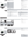
*NOTA: collegamento da effettuare sui due strumenti posti all’estremità della rete locale, la connessione deve essere realizzata il più vicino possibile al connettore
**NOTA: le tensioni delle uscite analogiche optoisolate sono riferite al morsetto N1
SCHEMA DI COLLEGAMENTO
SCHEDA SUPERIORE SCHEDA INFERIORE

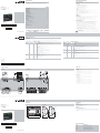
Modbus RS485
485
MYK connection
MCX08M2 - TOP
MCX08M2 - BOTTOM
PWM-PPM
0/10 Vdc
0/10 V
optoinsulated
NTC, 0/1 V, 0/5 V,
0/10 V, PT1000
To the AI
(100 mA max)
To the AI
(120 mA max)
Danfoss
80G8036.04
Not
used
110
140 6063
Danfoss
80G8037.01
ww w.danfoss.com/mcx
Via San Giuseppe 38/G
31015 Conegliano
(TV) Italy
Tel: +39 0438 336611
Fax: +39 0438 336699
www.danfoss.com
ww w.danfoss.com/mcx
AN19428642405201-000601
3106000680
AN19428642405201-000601
3106000680
GENERAL FEATURES
MCX08M2 is an electronic controller that holds all the typical functionalities of MCX controllers in the compact
size of 8 DIN modules: programmability, connection to the CANbus local network, Modbus RS485 serial
communication interface.
It is moreover available in the version with and without display and power supply 110-230 Vac or 24 Vac.
MCX08M2
ANALOG INPUTS
NTC, 0/1 V, 0/5 V, 0/10 V, PT1000, selectable via software 4
Universal NTC, Pt1000, 0/1 V, 0/5 V, 0/10 V, ON/OFF, 0/20 mA, 4/20 mA, selectable via software 4
Total number 8
DIGITAL INPUTS
Voltage free contact 8
Total number 8
ANALOG OUTPUTS
0/10 V DC optoinsulated 2
0/10 V DC, PWM, PPM selectable via software 2
Total number 4
DIGITAL OUTPUTS
SPST relay 16 A (normally open contacts) 2
SPST relay 8 A (normally open contacts) 2
SPDT relay 8 A (changeover contacts) 4
SSR 1A (optional, in alternative with 2 relays) 2
Total number 8
OTHERS
Power supply 24 V AC / 20/60 V DC •
Power supply 110 V / 230 V AC •
Connection for programming key •
Connection for remote display and keyboard •
Buzzer •
CANbus •
RTC clock •
Modbus RS485 serial interface •
Dimensions (DIN modules) 8
Mounting DIN rail
AN19428642405201-000601 / 520H11054 - MCX08M2 instruction sheet - P.N. 3106000680 - 15-310600068-D
GENERAL FEATURES AND WARNINGS
PLASTIC HOUSING FEATURES
- DIN rail mounting complying with EN 60715
- Self extinguishing V0 according to IEC 60695-11-10 and glowing/hot wire test at 960 °C according to IEC 60695-2-12
- Ball test: 125 °C according to IEC 60730-1. Leakage current: ≥ 250 V according to IEC 60112
OTHER FEATURES
- Operating conditions CE: -20T60 / UL: 0T55, 90% RH non-condensing
- Storage conditions: -30T80, 90% RH non-condensing
- To be integrated in Class I and/or II appliances
- Index of protection: IP40 only on the front cover
- Period of electric stress across insulating parts: long
- Suitable for use in environments with degree of pollution 2
- Category of resistance to heat and fire: D
- Immunity against voltage surges: category II
- Software class and structure: class A
CE MARK
This product is designed to comply with the following EU standards:
• Low voltage directive LVD 2014/35/EU:
- EN60730-1: 2011 (Automatic electrical control for household and similar use. General requirements)
- EN60730-2-9: 2010 (Particular Requirements for Temperature Sensing Controls)
• Electromagnetic compatibility EMC directive 2014/30/EU:
- EN 61000-6-3: 2007 +A1: 2011 (Emission standard for residential, commercial and light-industrial environments)
- EN 61000-6-2: 2005 (Immunity for industrial environments)
• RoHS directive 2011/65/EU and 2015/863/EU:
- EN50581: 2012
UL APPROVAL
UL file: E31024
GENERAL WARNINGS
- Every use that is not described in this manual is considered incorrect and is not authorised by the manufacturer
- Verify that the installation and operating conditions of the device respect the ones specified in the
manual, specially concerning the supply voltage and environmental conditions
- This device contains live electrical components therefore all the service and maintenance operations
must be performed by qualified personnel
- The device can’t be used as a safety device
- Liability for injury or damage caused by the incorrect use of the device lies solely with the user
INSTALLATION WARNINGS
- Mounting position recommended: vertical
- The installation must be executed according the local standards and legislation of the country
- Always operate on the electrical connections with the device disconnected from the main power supply
- Before carrying out any maintenance operations on the device, disconnect all the electrical connections
- For safety reasons the appliance must be fitted inside an electrical panel with no live parts accessible
- Don’t expose the device to continuous water sprays or to relative humidity greater than 90%.
Avoid exposure to corrosive or pollutant gases, natural elements, environments where explosives or
mixes of flammable gases are present, dust, strong vibrations or chock, large and rapid fluctuations in
ambient temperature that in combination with high humidity can condensate, strong magnetic and/or
radio interference (e.g. transmitting antennae)
- When connecting loads beware of the maximum current for each relay and connector
- Use cable ends suitable for the corresponding connectors. After tightening the screws of connectors,
slightly tug the cables to check their tightness
- Use appropriate data communication cables. Refer to the Fieldbus Installation Guide for the kind of cable to be
used and setup recommendations
- Reduce the path of the probe and digital inputs cables as much as possible, and avoid spiral paths
enclosing power devices. Separate from inductive loads and power cables to avoid possible electromagnetic noises
- Avoid touching or nearly touching the electronic components fitted on the board to avoid electrostatic discharges
Danfoss can accept no responsibility for possible errors in catalogues, brochures and other printed material. Danfoss reserves the right to alter its products without notice. This also applies to products
already on order provided that such alterations can be made without subsequential changes being necessary in specifications already agreed.
All trademarks in this material are property of the respective companies. Danfoss and the Danfoss logotype are trademarks of Danfoss A/S. All rights reserved.
I/O TYPE NUMBER SPECIFICATIONS
Digital
inputs
Voltage free
contact
8
DI1 to DI8
Current consumption: 10 mA
Analog
outputs
0/10 V DC
optoinsulated
2
AO3, AO4
Analog outputs optoinsulated 0/10 V DC minimum load 1K Ω (10 mA) for each output
PWM,
PPM,
0/10 V DC
2
AO1, AO2
Analog outputs selectable via software between:
- 0/10 V dc minimum load 1K Ω (10 mA) for each output
- pulsing output, synchronous with the line, at modulation of impulse position (PPM)
or modulation of impulse width (PWM)
- pulsing output, at modulation of impulse position (PPM) with range 20 Hz to 1 KHz:
open circuit voltage: 6.8 V
Analog
inputs
NTC
0 / 1V
0 / 10V
PT1000
4
AI5 to AI8
Analog inputs selectable via software between:
- 0 / 1 V, 0 / 5 V, 0 / 10 V : impedance is greater than 1M Ω
- NTC (10 kΩ at 25 °C)
- Pt1000
Universal 4
AI1 to AI4
Universal analog inputs selectable via software between:
- ON/OFF (current: 20 mA)
- 0/1 V, 0/5 V, 0/10 V : impedance is greater than 1M Ω
- 0/20 mA, 4/20 mA
- NTC (10 kΩ at 25 °C)
- Pt1000
12 V+ power supply 12 V DC, 120 mA max for 4/20 mA transmitter (total on all outputs)
5 V+ power supply 5 V DC, 100 mA max for 0/5 V transmitter (total on all outputs)
TECHNICAL SPECIFICATIONS
POWER SUPPLY
85 – 265 V AC, 50/60 Hz. Maximum power consumption: 20 VA. Insulation between power supply and the extra-low voltage: reinforced
20 – 60 V DC e 24 Vac ± 15% 50/60 Hz SELV. Maximum power consumption: 10 W, 17 VA. Insulation between power supply and the extra-low voltage: functional
I/O TYPE NUMBER SPECIFICATION
Digital
outputs
Relay 8
Insulation between relay: functional
Insulation between relays and the extra-low voltage parts: reinforced
Total current load limit: 32 A
C1-NO1, C2-NO2
High inrush current (80 A - 20 ms) normally open contact relays 16 A:
- characteristics of each relay:
10 A 250 V AC for resistive loads - 100.000 cycles
3.5 A 230 V AC for inductive loads - 230.000 cycles with cos(phi) = 0.5
C5-NO5, C6-NO6
Normally open contact relays 8 A:
- characteristics of each relay:
6 A 250 V AC for resistive loads - 100.000 cycles
4 A 250 V AC for inductive loads - 100.000 cycles with cos(phi) = 0.6
C3-NO3-NC3, C4-NO4-NC4, C7-NO7-NC7, C8-NO8-NC8
Changeover contacts relay 8 A:
- characteristics of each relay:
6 A 250 V AC for resistive loads - 100.000 cycles
4 A 250 V AC for inductive loads - 100.000 cycles with cos(phi) = 0.6
Solid State Relay 2 Insulation between SSR and relays: functional
Insulation between SSR and the extra-low voltage parts: reinforced
Type of SSR action: 1C (micro-interruption)
C5-NO5, C6-NO6
Solid State Relays 1A, with AC Zero-crossing output:
- characteristics of each relay
load current 0.5A
load voltage: 24 – 230 Vac
CONNECTION DIAGRAM
TOP BOARD BOTTOM BOARD
*NOTE: connection has to be made on the first and last local network units, make the connection as close as possible to the connector
**NOTE: optoinsulated analog outputs voltages are referenced to contact N1
CONNECTIONS
TOP BOARD
- Analog output 1-4 connector
7 screw plug-in connector type pitch 5 mm: section cable 0.2-2.5 mm²
- Analog input 1-4 connector
11 way screw plug-in connector type pitch 5 mm: section cable 0.2-2.5 mm²
- Digital input 1-8 connector
10 way screw plug-in connector type pitch 5 mm: section cable 0.2-2.5 mm²
- Analog input 5-8 connector
5 way screw plug-in connector type pitch 5 mm: section cable 0.2-2.5 mm²
BOTTOM BOARD
- Power supply connector
2 way screw plug-in connector type pitch 5 mm: section cable 0.2-2.5 mm²
- CAN connector
4 way screw plug-in connector type pitch 5 mm: section cable 0.2-2.5 mm²
- CAN-RJ connector
6/6 way telephone RJ12 plug type
- RS485 connector
3 way screw plug-in connector type pitch 5 mm: section cable 0.2-2.5 mm²
- Connettore digital output 1-2
4 way screw plug-in connector type pitch 5 mm: section cable 0.2-2.5 mm²
- Digital output 3-4 connector
6 way screw plug-in connector type pitch 5 mm: section cable 0.2-2.5 mm²
- Digital output 5-6 connector
4 way screw plug-in connector type pitch 5 mm: section cable 0.2-2.5 mm²
- Digital output 7-8 connector
6 way screw plug-in connector type pitch 5 mm: section cable 0.2-2.5 mm²
DIMENSIONS
Display LCD
PRODUCT PART NUMBERS
CODE DESCRIPTION
080G0293 MCX08M2, 24V, RS485, Single Pack
080G0307 MCX08M2, 230V, LCD, RS485, Single Pack
080G0310 MCX08M2, 24V, LCD, RS485, Single Pack
080G0303 MCX08M2, 24V, RS485, Industrial Pack (24 pcs)
080G0314 MCX08M2, 230V, RS485, 2SSR, Industrial Pack (24 pcs)
080G0315 MCX08M2, 24V, LCD, RS485, Industrial Pack (24 pcs)
080G0316 MCX08M2, 230V, RS485, Industrial Pack (24 pcs)
DISPOSAL INSTRUCTION
- Equipment containing electrical components may not be disposed together with domestic waste. It
must be separately collected with electrical and electronic waste according to local and valid legislation.
Instruction sheet
Electronic controller
MCX08M2
Instruction sheet
Electronic controller
MCX08M2
© Danfoss A/S (RAC-DCS-IMCGP/vt), 2019.11
USER INTERFACE
DISPLAY LCD
- display mode: STN blue transmissive
- backlight: white LED backlight adjustable via software
- display format: 128x64 dots
- active visible area : 58x29 mm
- contrast: adjustable via software
KEYBOARD
- number of keys: 6
- keys function is settled by the application software
DISPLAY SETTINGS ADJUSTMENT
- Setting of the LCD display like contrast and brightness might need to be adjusted due to external ambient factors.
Press and release simultaneously the Enter and X key after power ON to access the BIOS menu and select the
DISPLAY menu. Use UP and DONWN arrow keys to adjust the contrast or the brightness of the display at the
desired level.
-
 1
1
-
 2
2


in altre lingue
- English: Danfoss MCX08M2 Installation guide
Documenti correlati
-
Danfoss MCX08M2 Guida d'installazione
-
-
-
-
-
-
-
-
-