
Page 1 of 1
KATHREIN Digital Systems GmbH • Anton-Kathrein-Straße 1–3 • 83022 Rosenheim • Germany
Rosenheim, 31.03.2019
Information über gesellschaftsrechtliche Änderung
Information about change in corporate legal status
Zum 1. April 2019 geht das Geschäftsfeld „Terrestrial & Satellite Reception“ der
KATHREIN SE (vormals KATHREIN-Werke KG) auf die KATHREIN Digital Systems
GmbH über.
Die neuen Firmendaten lauten ab 01.04.2019 wie folgt:
KATHREIN Digital Systems GmbH
Anton-Kathrein-Str. 1–3
83022 Rosenheim, Deutschland
Steuer-Nr.: 156/117/31083
UST-Ident-Nr.: DE311049363
Registergericht: Traunstein, HRB 25841
______________________________________________________________________________
As of 1 April 2019, KATHREIN SE’s (formerly KATHREIN-WERKE KG) “Terrestrial &
Satellite Reception” business unit will be transferred to KATHREIN Digital Systems
GmbH (limited liability company).
From 1 April 2019, the new company data are:
KATHREIN Digital Systems GmbH
Anton-Kathrein-Str. 1–3
83022 Rosenheim, Germany
Tax ID No.: 156/117/31083
VAT Reg. No.: DE311049363
Commercial Register: Traunstein, HRB 25841
KATHREIN
Digital Systems GmbH
Anton
-Kathrein-Straße 1–3
83022 Rosenheim
Germany
www.kathrein
-ds.com
info
@kathrein-ds.com
Executive Board
:
Michael Auer
Uwe Thumm
US
t-ID-Nr.: DE 311 049 363
Steuer
-Nr.: 156/117/31083
GLN:
40 63242 00000 5
WEEE
-Reg.-Nr.: DE 66199153
Registered Office: Rosenheim, DE
Commerc
ial Register: Traunstein, HRB 25841
Commerzbank AG
IBAN:
DE24 7114 0041 0611 9002 00
BIC:
COBADEFFXXX
936500001

1 / 8
UFG 810 20610122
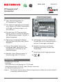
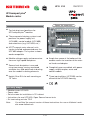
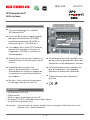
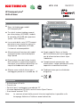
UFOcompact plus
®
Grundeinheit
Merkmale
Zehn Hotplug-Steckplätze für
UFOcompact plus
®
-Module
Drei separate Hotplug-Systemsteckplät-
ze für Netzteil (UFN 800), Steuermodul
(UFX 800) und Erweiterungen (z. B.:
UVO 830 etc.)
Kassetten der UFO
®
compact-Serie
können montiert und über den Adapter
UFZ 800 betrieben werden, System ist
abwärtskompatibel
Spannungsversorgung der Module
und Kommunikation über High Speed-
Backplane
Sichere Wärmeabfuhr durch zwei
energiesparende, überwachte Lüfter
und optimierte Luftführung an den
Modulkühlkörpern
Bauhöhe: Neun Höheneinheiten für
W
andmontage oder 19“-Schrank
UFN 800
Backplane
UFX 800
Platz für Erweiterungen
Großzügige Freiräume im Boden der
Grundeinheit für die Kabelführung der
externen Zuleitungen und Adapter
Komplett vormontiert mit Netzteil,
Ausgangssammelfeld, Deckel und
Steuermodul
V
orhaltung für drei Eingangsverteiler
Lieferumfang
• Grundeinheit UFG 810
• Netzkabel
• Schrauben-Set für die Montage im 19“-Schrank
• Anwendungshinweis UFG 810, Open Source Lizenztexte
• 9 x Abschlusswiderstand 75 Ω
Hinweis: Die aktuelle Version dieses Anwendungshinweises fi nden Sie auf der Kathrein-
Homepage: www.kathrein.de

2 / 8
Technische Daten
Montageart Einbau in 19“-Schrank und Wandmontage
Anzahl der Hotplug-System-
steckplätze
Zehn Module, ein Netzteil (UFN 800 vormontiert), zwei
Funktionsmodule (UFX 800 vormontiert und ein weiteres)
Netzteil (UFN 800, 20610121)
Netzspannung V/Hz 230 ± 10 %/50 ... 60
Max. Leistungsaufnahme W 437
Sekundärspannung/max.
zulässiger Strom
V/A 12,3/32,5
Signalisierung LED Grün (Normalbetrieb), Rot (Unterspannung bzw.
Überstrom), Rot blinkend (Überspannung)
Allgemeines
Lüfter 2
Abmessungen (H x B x T) mm 399 x 483 x 266
Zulässige Umgebungstem-
peratur
°C -20 ... +50
Gewicht kg 12,8
Sicherheitshinweise
WARNUNG HEISSE OBERFLÄCHEN NICHT BERÜHREN
Im Regelbetrieb kann bei erhöhter Umgebungstemperatur die Oberfl ächen-
temperatur Werte von mehr als 60 °C einnehmen.
Kommt es zu einer Übertemperaturabschaltung besteht Gefahr durch heiße
Metallteile!
Beim Einsatz von UFOcompact plus
®
-Anlagen in öffentlich zugänglichen Räumen ist die
Anlage mit dem Frontdeckel zu verschließen.
• Das Gerät muss von einem qualifi zierten Techniker nach den jeweils
geltenden nationalen und örtlichen Sicherheitsstandards und Vorschriften
installiert werden.
• Die beschriebenen Geräte dienen ausschließlich der Installation von
Satelliten-Empfangsanlagen
• Jegliche anderweitige Nutzung oder die Nichtbeachtung dieses Anwen-
dungshinweises hat den Verlust der Gewährleistung bzw. Garantie zur
Folge.
• Die Geräte dürfen nur in trockenen Innenräumen auf festem Untergrund
montiert werden.
• Nicht auf oder an leicht entzündlichen Materialien montieren.
• Die Geräte sind mit einer Potenzial-Ausgleichsleitung
(Cu, mindestens 4 mm²) zu versehen.

3 / 8
Stromführendes Gerät
• Nicht öffnen oder am Gerät manipulieren!
• Bei Arbeiten an der Anlage immer Netzstecker aus der Steckdose ziehen!
• Auf ausreichenden Abstand achten! Nach allen Seiten mind. 5 cm!
• Nicht über Kopf montieren
• Für die Geräteentwärmung muss freie Luftzirkulation möglich sein.
Überhitzungsgefahr!
Achtung:
• Messungen an den Backplane-Steckern sind nicht zulässig (Kurzschluss-
gefahr!)
• Die Lüftungsschlitze dürfen nicht abgedeckt werden
• Auf das Netzteil und die Lüfter dürfen keine mit Flüssigkeit gefüllten
Gegenstände gestellt werden
• Das Netzteil und die Lüfter dürfen nicht Tropf- oder Spritzwasser ausge-
setzt sein
• Der Netzstecker muss ohne Schwierigkeiten zugänglich und benutzbar
sein
• Das Netzteil kann nur durch Ziehen des Netzsteckers der UFG 810 sicher
vom Netz getrennt werden
• Die Grundeinheit ist an eine Netzsteckdose mit Schutzleiter anzuschließen
• Das Gerät darf nur mit funktionierenden Lüftern betrieben werden
• Finger und andere Körperteile sind von sich bewegenden Teilen wie z. B.
den Lüftern unbedingt fernzuhalten. Es besteht Verletzungsgefahr!
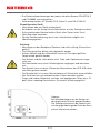
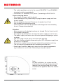
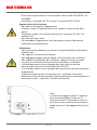
Hinweis:
Bei Wandmontage muss die Anlage mit
der dargestellten Schelle geerdet werden.
Die Erdungsschelle kann bei Bedarf auch
auf die gegenüberliegende Seite der Basis-
einheit ummontiert werden.
• Die Sicherheitsbestimmungen der jeweils aktuellen Normen EN 60728-11
und EN 60065 sind zu beachten.
• Verbindungsstecker: HF-Stecker 75 Ω (Serie F) nach EN 61169-24.

4 / 8
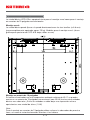
Montageschritte
Die Basiseinheit UFG 810 ist sowohl für die Wandmontage als auch für den Einbau in
handelsübliche 19“-Schränke geeignet.
Wandmontage:
Die Grundeinheit kann direkt mit drei Schrauben (ø 6-8 mm) an der Wand befestigt werden
(Gewicht voll bestückt: ca. 25 kg). Maße für die Wandmontage: (siehe Grafi k Rückseite
UFG 810 unten, Angaben in mm)
Einbau in 19“-Schrank
In klimatisierten Räumen mit einer maximalen Umgebungstemperatur von 40 °C können
in einem klassischen 19“-Schrank (mit 40 HE) bis zu vier Basiseinheiten übereinander
montiert werden. Zwischen den Einheiten ist ein Mindestabstand von einer Höheneinheit
(1 HE) einzuhalten!
Hinweis:
Zum Einbau in 19“-Schränke müssen die Erdungsschelle sowie eventuelle sonstige seit-
liche Anbauteile entfernt werden.

5 / 8
Montageschritte
1. Basiseinheit montieren und Potenzialausgleich vorschriftsmäßig (DIN EN 60728-11 und
DIN EN 60065) durchführen.
2. Sat-ZF-Kabel/Niederführungen (H und V) können im Bodenbereich vorbereitet/geparkt
werden. Das Bodenblech kann zur Kabeleinführung/-montage entfernt werden.
3. 230 V~ Stromkabel anschließen (kann ebenfalls im Bodenbereich geführt/verlegt
werden).
Inbetriebnahme
1. Anlage, wie unter „Montageschritte“ beschrieben, installieren
2. UFOcompact plus
®
-Module einschieben und festschrauben. Es können auch ältere
UFOcompact
®
-Kassetten verbaut werden; dazu wird pro UFOcompact
®
-Kassette ein
Kanalzug-Adapter UFZ 800 (Bestellnummer: 20610124) benötigt
3. Sat-ZF-Niederführungen (H und V) können direkt auf die Module (F-Connector)
gesteckt oder über eine Matrix geführt werden. Alle UFOcompact plus
®
-Module sind
DiSEqC™-fähig.
4. HF-Verbindungsleitung(en) (F-Quick) zwischen den Ausgangsbuchse(n) der Module
(F-Connector) und dem Ausgangssammelfeld im Kopfteil der Basiseinheit stecken.
Nicht benutzte Buchsen sind mit den mitgelieferten Abschlusswiderständen zu bestü-
cken
5. Anlage an das Netz anschließen
6. Über eine Management-Schnittstelle des zentralen Steuermoduls UFX 800 können die
UFOcompact plus
®
-Module und UFOcompact
®
-Kassetten konfi guriert werden. Dies ist
vor Ort mit einem Laptop oder per Fernbedienung über TCP/IP mittels der Manage-
ment-Software USW 800 (kostenloser Download von „www.kathrein.de“) möglich
7. Wenn das Stromnetz die spezifi zierten zulässigen Spannungswerte (230 V~ ± 10%)
nicht einhält, empfehlen wir den Einsatz einer USV (unterbrechungsfreie Stromversor-
gung), die diese Schwäche des Stromnetzes ausgleicht.
Bedienung
Die Steuerung des Kanalzuges übernimmt das zentrale Steuermodul UFX 800 –
die Kontroll-Schnittstelle für alle in der UFG 810 eingesetzten Module und Kassetten.
Die Bedienung des Kanalzuges erfolgt über die graphische Benutzeroberfl äche (GUI) der
USW 800 Management-Software. Die Bedienung ist Teil der Bedienungsanleitung der
USW 800, welche als PDF-Dokument in der Management-Software enthalten ist.
Hinweis:
Die aktuelle Version der USW 800 und ihrer Bedienungsanleitung stehen kostenfrei auf der
Kathrein-Homepage „www.kathrein.de“ zum Download bereit.
Installieren Sie die USW 800-Management-Software auf einem Computer. Verbinden Sie
den LAN/Ethernet Anschluss Ihres Computers mit einem der zwei LAN/Ethernet Anschlüs-

6 / 8
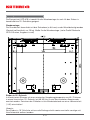
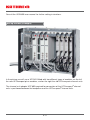
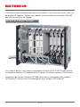
Aufbauvariante (Beispiel)
Im Bild oben sehen Sie eine gemischte Bestückung einer UFG 810. Auf der linken Seite
die neuen UFOcompact plus
®
-Module und rechts die alten UFOcompact
®
-Kassetten.
Der für den Anschluss der UFOcompact
®
-Kassetten benötigte Kanalzug-Adapter UFZ 800
befi ndet sich zwischen der Backplane und den UFOcompact
®
-Kassetten.
se der UFX 800 (CAT5 oder höher empfohlen, gekreuzt oder ungekreuzt). Sie haben nun
Zugriff auf alle Geräteparameter. Die weiteren Einstellanweisungen entnehmen Sie bitte
der Bedienungsanleitung der USW 800.

7 / 8
Elektronische Geräte gehören nicht in den Hausmüll, sondern müssen - gemäß
Richtlinie 2002/96/EG DES EUROPÄISCHEN PARLAMENTS UND DES RATES
vom 27. Januar 2003 über Elektro- und Elektronik-Altgeräte fachgerecht entsorgt
werden. Bitte geben Sie dieses Gerät am Ende seiner Verwendung zur Entsorgung
an den dafür vorgesehenen öffentlichen Sammelstellen ab.
Entsorgungs-/Recycling-Hinweis
Lizenztexte für Open Source Licenses
Auf Grund des Umfanges der Lizenztexte werden diese als separate Unterlage (9364681)
beigepackt.
Wartung
Um einen langen und störungsfreien Betrieb zu gewährleisten, empfehlen wir, die
Anlage(n) regelmäßig zu warten, d.h., die Lüfter bzw. die Lüftungsschlitze mindestens
einmal im Jahr zu reinigen (Staub und sonstige Verunreinigungen entfernen). Ferner
empfehlen wir die Lüfter generell alle 6-7Jahre auszutauschen. Die Lüftereinheit kann für
den Austausch der Lüfter komplett entnommen werden. Der Tausch der Lüfter ist auch
ohne Betriebsunterbrechung der Anlage möglich - aber nicht empfohlen; es wird i.d.R. kein
Werkzeug benötigt. Der Austausch ist zügig durch zu führen, um eine Überhitzung der
Anlage zu vermeiden. Vorgehensweise beim Lüftertausch:
1. Lösen der drei frontseitigen Befestigungsschrauben (Rändelschrauben)
2. Anheben der Lüftereinheit um einige Zentimeter und Lösen der zwei Steckverbin-
dungen für die Einzellüfter (12 V) im linken Teil der Anlage
3. Lüftereinheit nach vorne komplett herausziehen
4. Tausch der Einzellüfter und Montage der Lüftereinheit in umgekehrter Reihenfolge
Finger und andere Körperteile sind von sich bewegenden Teilen wie
z. B. den Lüftern unbedingt fernzuhalten. Es besteht Verletzungsgefahr!

936.4578/a/VKDT/1113/DE - Technische Änderungen vorbehalten!
Internet: www.kathrein.de
KATHREIN-Werke KG • Anton-Kathrein-Straße 1-3 • Postfach 10 04 44 • 83004 Rosenheim • Deutschland • Telefon +49 (0) 8031 184-0 • Fax +49 (0) 8031 184-306

1 / 8
UFG 810 20610122
UFOcompact plus
®
Module carrier
Features
Ten hot-plug insert positions for
UFOcompact plus
®
modules
Three separate hot-plug system insert
positions for power supply unit
(UFN 800), control module (UFX 800)
and extensions (e.g. UVO 830, etc.)
UFO
®
compact series channel units
can be installed and operated over the
UFZ 800 adapter. The system is down-
wards compatible
Module voltage supply and communica-
tion over high-speed backplane
Secure heat dissipation is ensured
using two energy-saving, monitored
extractor fans and optimised air ducting
over the module’
s cooling elements
Height: Nine RUs for wall mounting or
19” racks
UFN 800
Backplane
UFX 800
Space for expansion
Ample free space at the bottom of the
module carrier for insertion of the exter-
nal leads and adapter
Completely pre-assembled, with power
supply
, output coupler, cover and
control module
Three input splitters (UFZ 300) can be
affi
xed to the UFG 810 housing
Delivery scope
• Module carrier UFG 810
• Power cable
• Set of screws for installation in 19” cabinet
• Instructions for use UFG 810, Open Source license texts
• 9 x terminating resistor 75 Ω
Note: You will fi nd the current version of these instructions for use on Kathrein’s web-
site: www.kathrein.de

2 / 8
Technical data
Type of mounting Installation in 19” cabinets or for wall mounting
Number of hot-plug system
insert positions
Ten modules, one power supply unit (UFN 800
pre-assembled), two functional modules (UFX 800 pre-
assembled, and an additional one)
Power supply
(UFN 800, 20610121)
Mains voltage V/Hz 230 ± 10 %/50 ... 60
Power consumption max. W 437
Secondary voltage/max.
permissible current
V/A 12.3/32.5
Signalisation LED Green (normal operation), Red (undervoltage or excess
current), Red fl ashing (overvoltage)
General
Extractor fan 2
Dimensions (H x W x D) mm 399 x 483 x 266
Permissible ambient tempera-
ture
°C -20 ... +50
Weight kg 12.8
Safety instructions
WARNING HOT SURFACE DO NOT TOUCH
During normal operation and increased ambient temperature, the surface
temperature may exceed 60 °C.
Should thermal cut-out occur, there may be danger due to hot metal parts!
When using UFOcompact plus
®
in publicly accessible spaces, the front cover of the system
must be closed.
• The unit must be installed by qualifi ed personnel in compliance with the
local and national security standards and regulations.
• The equipment described is designed solely for installation in satellite
receiver systems.
• Any other use, or failure to comply with these instructions, will result in
voiding of warranty cover.
• The equipment may only be installed in dry areas indoors.
• Do not mount it on or against easily fl ammable materials.
• The equipment must be connected the equipotential bonding rail
(Cu, at least 4 mm
2
).

3 / 8
Current-carrying device
• Do not open or tamper with the device!
• When working on the system always unplug the power supply unit from
the wall socket!
• Ensure adequate clearance! Clearance all round at least 5 cm!
• Not suitable for overhead mounting
• Free circulation of air must be possible to discharge the heat emitted by
the unit. Danger of overheating!
Attention:
• Measurements on the backplane plugs not allowed (Risk of short circuits!)
• Do not cover the louvres
• Do not place liquid-fi lled items on top of the power supply unit or the fans.
• The power supply and louvres are not to be exposed to dripping or splash-
ing water
• The mains plug must be easily accessible and operable.
• The only reliable method of disconnecting the UFG 810 power supply from
the mains is to unplug it.
• Connect the module carrier to the wall outlet with a protective earthing
• The unit may only be operated with functioning extractor fans
• Keep fi ngers and other body parts away from any moving components
e.g. extractor fans at all times. Otherwise you may be injured!
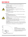
Note:
For wall installation, the system must be
earthed with the earthing clamp pictured. If
required, the earthing clamp may also be
installed on the opposite side of the module
carrier.
• The safety regulations set out in the current EN 60728-11 and EN 60065
standards must be complied with.
• Connectors: RF connector,75 Ω (series F) according to EN 61169-24

4 / 8
Installation steps
The module carrier UFG 810 is not only designed for wall mounting but also for installation
in 19” cabinets.
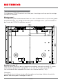
Wall mounting:
the module carrier can be directly fi xed to the wall using three screws (ø 6-8 mm).
Weight when fully equipped: approx. 25 kg. Dimensions for wall mounting:
(see illustration of UFG 810 rear panel below, values in mm).
Installation in 19” cabinet
In air-conditioned rooms with a maximum ambient temperature of 40 °C, up to four module
carriers can be stacked one above the other in a standard 19“ cabinet (with 40 RU). A
minimum of one height unit (1 RU) clearance should be left between each of the units
Note:
For installation in 19” racks, the two side pieces and the earth clip must be removed.

5 / 8
Installation steps
1. Fit the module carrier and connect potential equalisation to the regulations
(DIN EN 60728-11 and DIN EN 60065).
2. Sat-IF cables/drop cables (H and V) can be prepared/parked in the bottom section.
The bottom plate can be removed to insert or install cables.
3. Connect 230 V power cable (can also be lead/laid) in the bottom section.
Start-up
1. Install the system as described under “Installation procedure”
2. Insert UFOcompact plus
®
modules and tighten. Older UFOcompact
®
channel units can
also be built in. To do so, one UFZ 800 (Order no. 20610124) channel unit adapter is
required per UFOcompact
®
channel unit
3. Sat-IF drop cables (H and V) can be inserted directly into the modules (F-type connec-
tor) or through a matrix. All UFOcompact plus
®
modules are DiSEqC™-capable.
4. Insert RF connector cable(s) (F-Quick) between the output socket(s) of the module
(F-type connector) and the output coupler in the head piece of the module carrier.
Unused RF female connectors are to be fi tted with terminating resistors.
5. Connect system to network
6. The UFOcompact plus
®
modules and UFOcompact
®
channel units can be confi gured
over a management interface of the UFX 800 central
control module. This can be done
on site with a laptop or over remote conrol via TCP/IP using the management software
USW 800 (download available free of charge from “www.kathrein.de”)
7. If the power supply system does not maintain the specifi ed permissible voltage values
(230 V~ ± 10%), we recommend using an uninterrupted power supply unit that com-
pensates this weakness of the electricity network.
Operation
Control of the channel unit is done over the control module UFX 800, the control interface
for all modules and channel units installed in the UFG 810 module carrier.
Operation of the channel unit is performed via the graphical user interface (GUI) of the
USW 800 control software. Instructions on how to operate are found in the USW 800
operating manual supplied as a pdf in the management software.
Note: The current version of the USW 800 and its operation manual are available free to
download on the Kathrein website “www.kathrein.de”.
Install the USW 800 Management software on a computer. Connect your computer’s
LAN/Ethernet port to one of the two LAN/Ethernet ports on the UFX 800 (CAT 5 or higher is
recommended, twisted pair). You now have access to all the device parameters.

6 / 8
Set-up variant (example)
In the picture you will see a UFG 810 fi tted with two different types of modules; on the left
the new UFOcompact plus
®
modules, and on the right the old UFOcompact
®
channel units.
The channel unit adapter UFZ 800 required for connection of the UFOcompact
®
channel
units is positioned between the backplane and the UFOcompact
®
channel units.
Consult the USW 800 user manual for further setting instructions.

7 / 8
Electronic equipment is not domestic waste - it must be disposed of properly in
accordance with directive 2002/96/EC OF THE EUROPEAN PARLIAMENT AND
THE COUNCIL dated 27
th
January 2003 concerning used electrical and electronic
appliances. At the end of its service life, take this device for disposal at a designated
public collection point.
Waste / Recycling note
License texts for Open Source Licenses
Due to the scope of the license texts, these have been provided as a separate document
(9364681).
Service
In order to guarantee a long and undisturbed service life, we recommend servicing the sys-
tems on a regular basis, e.g. cleaning the fans or louvres at least once a year (remove dust
and other impurities). Furthermore, we recommend exchanging the fans every 6-7 years.
The fan unit can be completely removed for exchange. The fans can also be exchanged
without interrupting operation; however this is not recommended. In general, no tools are
required. Fan exchange should be performed quickly in order to prevent system overheat-
ing. The exchange procedure is to be done as follows:
1. Loosen the three fi xing screws (thumbscrews) on the front
2. Lift the fan unit a few centimeters and loosen the two optical connectors for the
individual fans (12 V) in the left section of the system
3. Completely pull out the fan unit towards the front
4. Exchange of individual fans and installation of fan unit in reverse order
Keep fi ngers and other body parts away from any moving components
e.g. extractor fans at all times. This can cause injury!

936.4578/a/VKDF/1113/GB - Technical data subject to change!
Internet: www.kathrein.de
KATHREIN-Werke KG • Anton-Kathrein-Straße 1-3 • P.O. Box 10 04 44 • 83004 ROSENHEIM • GERMANY • Phone +49 8031 184-0 • Fax +49 8031 184-306

1 / 8
UFG 810 20610122
UFOcompact plus
®
Unité de base
Caractéristiques
Dix slots hotplug pour les modules
UFOcompact plus
®
Trois slots de système hotplug séparés
pour bloc d’alimentation (UFN 800),
module de commande (UFX 800) et
extensions (p. ex. : UVO 830 etc.)
Les modules de la série UFO
®
compact
peuvent être montées et utilisées via
l’adaptateur UFZ 800, le système est
rétrocompatible
Alimentation en tension des modules et
communication via fond de panier haute
vitesse
Évacuation de la chaleur sûre
grâce à deux ventilateurs surveillés
économiques en énergie et guidage de
l’air optimisé au niveau des radiateurs
des modules
Hauteur : Neuf unités de hauteur pour
le montage mural ou sur rack 19"
UFN 800
Fond de panier
UFX 800
Espace pour extensions
Grand espace libre dans fond de l’unité
de base pour le guidage des câbles des
connexions et des adaptateurs externes
Unité entièrement préassemblée avec
bloc d’alimentation, sortie groupée,
couvercle et module de commande
Préparation pour trois répartiteurs
d’entrée
Fournitures
• Unité de base UFG 810
• Câble secteur
• Kit de vis pour le montage sur rack 19"
• Consigne UFG 810, textes de licence Open Source
• 9 x résistance terminale 75 Ω
Remarque : Vous trouverez la version actuelle de ces consignes d’utilisation sur le site
Kathrein sous : www.kathrein.de

2 / 8
Données techniques
Type de montage Montage sur rack 19" et montage mural
Nombre de slots de système
hotplug
Dix modules, un bloc d’alimentation (UFN 800, prémonté),
deux modules de fonction (UFX 800 prémonté et un autre)
Bloc d’alimentation
(UFN 800, 20610121)
Tension secteur V/Hz 230 ± 10 %/50 ... 60
Puissance max. absorbée W 437
Tension secondaire/courant
max. admissible
V/A 12,3/32,5
Signalisation LED Vert (fonctionnement normal), rouge (sous-tension ou
surintensité), rouge clignotant (surtension)
Généralités
Ventilateur 2
Dimensions (h x l x p) mm 399 x 483 x 266
Température ambiante
admissible
°C -20 ... +50
Poids kg 12,8
Consignes de sécurité
AVERTISSEMENT NE PAS TOUCHER LES SURFACES BRULANTES
En service normal, la température de la surface peut atteindre plus de 60 °C
en cas de température ambiante élevée.
En cas de coupure pour des raisons de surchauffe, les parties métalliques
peuvent être très chaudes !
Si les installations UFOcompact plus
®
sont utilisées dans des locaux accessibles au public,
elles doivent être obturées par un couvercle avant.
• L’appareil doit être installé par un technicien qualifi é dans le respect des
normes de sécurité et des prescriptions nationales et locales en vigueur.
• Les dispositifs décrits ici sont exclusivement destinés à l’installation
d’appareils récepteurs satellite.
• Tout autre usage, de même que le non respect des présentes consignes,
entraînera l’annulation de la garantie.
• Les appareils ne doivent être montés que sur un support solide, dans des
environnements intérieurs non humides.
• Ne pas les installer sur ou à proximité de matériaux facilement
infl ammables.
• Ces dispositifs devront être pourvus d’une ligne équipotentielle
(Cu, 4 mm² minimum).

3 / 8
Appareil sous tension
• Ne pas ouvrir ou manipuler l’appareil !
• Systématiquement débrancher la fi che secteur de la prise avant
d’intervenir sur l’installation !
• Veiller à un dégagement suffi sant ! Dégagement minimal de 5 cm de
chaque côté !
• Ne pas monter en hauteur.
• L’évacuation de la chaleur de l’appareil suppose une libre circulation de
l’air. Risque de surchauffe !
Attention :
• Il est interdit d’effectuer des mesures sur les connecteurs de fond de
panier (danger de court-circuit !).
• Ne pas obstruer les orifi ces d’aération.
• Ne poser aucun objet contenant du liquide sur le bloc d’alimentation et les
ventilateurs.
• Le bloc d’alimentation et les ventilateurs doivent être à l’abri des gouttes et
des projections d’eau.
• La fi che secteur doit rester facilement accessible.
• Le bloc d’alimentation ne peut être séparé en toute sécurité du secteur
qu’en débranchant la fi che secteur de l’UFG 810.
• L’unité de base doit être branchée sur une prise secteur avec conducteur
de protection.
• L’appareil ne doit être mis en service qu’avec un ventilateur qui fonctionne.
• Ne pas approcher les doigts ou d’autres parties du corps des éléments en
mouvement, par ex. des ventilateurs. Il y a risque de blessures !
Remarque :
En cas de montage mural, l’installation
doit être mise à la terre à l’aide du collier
représenté. Si nécessaire, le collier de mise
à la terre peut également être monté sur le
côté opposé de l’unité de base.
• Respecter les consignes de sécurité des normes EN 60728-11 et
EN 60065 en vigueur.
• Connecteurs : connecteurs HF 75 Ω (série F) selon EN 61169-24.
La pagina si sta caricando...
La pagina si sta caricando...
La pagina si sta caricando...
La pagina si sta caricando...
La pagina si sta caricando...
La pagina si sta caricando...
La pagina si sta caricando...
La pagina si sta caricando...
La pagina si sta caricando...
La pagina si sta caricando...
La pagina si sta caricando...
La pagina si sta caricando...
La pagina si sta caricando...
La pagina si sta caricando...
La pagina si sta caricando...
La pagina si sta caricando...
La pagina si sta caricando...
La pagina si sta caricando...
La pagina si sta caricando...
La pagina si sta caricando...
La pagina si sta caricando...
-
 1
1
-
 2
2
-
 3
3
-
 4
4
-
 5
5
-
 6
6
-
 7
7
-
 8
8
-
 9
9
-
 10
10
-
 11
11
-
 12
12
-
 13
13
-
 14
14
-
 15
15
-
 16
16
-
 17
17
-
 18
18
-
 19
19
-
 20
20
-
 21
21
-
 22
22
-
 23
23
-
 24
24
-
 25
25
-
 26
26
-
 27
27
-
 28
28
-
 29
29
-
 30
30
-
 31
31
-
 32
32
-
 33
33
-
 34
34
-
 35
35
-
 36
36
-
 37
37
-
 38
38
-
 39
39
-
 40
40
-
 41
41


Kathrein 20610122 Manuale utente
- Tipo
- Manuale utente
- Questo manuale è adatto anche per
in altre lingue
- English: Kathrein 20610122 User manual
- français: Kathrein 20610122 Manuel utilisateur
- español: Kathrein 20610122 Manual de usuario
- Deutsch: Kathrein 20610122 Benutzerhandbuch
Documenti correlati
-
Kathrein UFZ 412/D Scheda dati
-
-
-
-
-
-
-
-
-
Kathrein Euroline UFE 341S Manuale utente