Yamaha GW10 Manuale del proprietario
- Categoria
- Strumenti musicali
- Tipo
- Manuale del proprietario

BEDIENUNGSANLEITUNG
MODE D’EMPLOI
OWNER’S MANUAL
VR57110 JEABR1CR13.2CP
VR57100 JEABR1CR13.2CP
GUITAR PERFORMANCE EFFECTOR

This product utilizes batteries or an external
power supply (adapter). DO NOTconnect this
product to any power supply or adapter other than
one described in the manual, on the name pIate,
or specifically recommended by Yamaha.
This Product should be used only with the compo-
nents supplied or; a cart, rack, or stand that is
recommended by Yamaha. If a cart, etc., is used,
please observe all safety markings and instruc-
tions that accompany the accessory product.
SPEClFlCATIONS SUBJECT TO CHANGE:
The information contained in this manual is
believed to be correct at the time of printing.
However, Yamaha reserves the right to change or
modify any of the specifications without notice or
obligation to update existing units.
This product, either aIone or in combination with
an amplifier and headphones or speaker/s, may
be capable of producing sound levels that could
cause permanent hearing loss. DO NOT operate
for Iong periods of time at a high volume level or
at a level that is uncomfortabIe. lf you experience
any hearing Ioss or ringing in the ears, you
should consult an audiologist. lMPORTANT: The
louder the sound, the shorter the time period
before damage occurs.
NOTlCE:
Service charges incurred due to Iack of knowl-
edge relating to how a function or effect
works(when the unit is operating as designed)are
not covered by the manufacturer’s warranty, and
are therefore the owners responsibility. Please
study this manual carefulIy and consult your
dealer before requesting service.
ENVIRONMENTAL lSSUES:
Yamaha strives to produce products that are both
user safe and environmentalIy friendIy. We
sincerely believe that our products and the
production methods used to produce them, meet
these goals . ln keeping with both the letter and
the spirit of the law, we want you to be aware of
the following:
Battery Notice: This product MAY contain a
small non-rechargeable battery which (if
applicabIe)is soldered in PIace. The average life
span of this type of battery is approximately five
years. When repIacement becomes necessary,
contact a qualified service representative to
perform the replacement.
This Product may also use “household”type
batteries. Some of these may be rechargeable.
Make sure that the battery being charged is a
rechargeable type and that the charger is in-
tended for the battery being charged.
When installing batteries, do not mix old batteries
with new, or with batteries of a different type.
Batteries MUST be installed correctly. Mismatches
or incorrect instalIation may result in overheating
and battery case rupture.
Warning: Do not attempt to disassemble, or
incinerate any battery. Keep alI batteries away
from chiIdren. Dispose of used batteries promptly
and as regulated by the laws in your area.
Note: Check with any retailer of household type
batteries in your area for battery disposal informa-
tion.
Disposal Notice: Should this Product become
damaged beyond repair, or for some reason its
useful life is considered to be at an end, pIease
observe aII IocaI, state, and federaI regulations
that relate to the disposal of products that contain
lead, batteries, plastics, etc. if your dealer is
unable to assist you, Please contact Yamaha
directly.
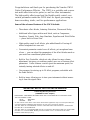
NAME PLATE LOCATlON:
The name Plate is located on the bottom of the
product. The model number, serial number, power
requirements, etc., are located on this plate. You
should record the seriaI number and the date of
purchase in the spaces provided beIow and retain
this manual as a permanent record of your
purchase.
Model GW10
Serial No.
Purchase Date
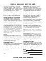
SPECIAL MESSAGE SECTION (USA)
PLEASE KEEP THIS MANUAL
92-BP

Congratulations and thank you for purchasing the Yamaha GW10
Guitar Performance Effector. The GW10 is a portable and conven-
ient multi-effect device for guitar (as well as other instruments).
The high-quality effect sound and the flexible pedal control over
certain parameters make the GW10 ideal for signal processing in
home recording, studio, and live performance applications.
Some of the advanced features of the GW10 include:
• Three basic effect blocks, featuring Distortion, Chorus and Delay.
• Additional effect types within each block, such as Compressor,
Overdrive, Crunch, Wah, Amp Simulator, Equalizer and Pitch Shifter
— plus a built-in Noise Gate.
• High-quality sound in all effects, plus added benefit of having all
effects integrated into one unit.
• Convenient parameter control over all effects, yet exceptional ease-
of-use — you can adjust the parameters of the effect blocks much as
you would on conventional pedal effects.
• Built-in Foot Controller, which not only allows for easy volume
adjustment, but gives you realtime control over one of various effect
parameters. It also features a switch (past the maximum point) for
instantly turning selected effects on and off.
• User memory for storing up to 20 effect programs, selectable with
the Pedal Switch.
• Built-in tuner, allowing you to tune your instrument without remov-
ing it from the signal chain.
IMPORTANT NOTICE FOR THE UNITED KINGDOM
Connecting the Plug and Cord
(YAMAHA PA-3 AC adaptor)
IMPORTANT: THE WIRES IN MAINS LEAD ARE COLOURED IN ACCORDANCE WITH
THE FOLLOWING CODE:
BLUE : NEUTRAL
BROWN : LIVE
As the colours of the wires in the mains lead of this apparatus may not correspond with the
coloured markings identifying the terminals in your plug, proceed as follows:
The wire which is coloured BLUE must be connected to the terminal which is marked with
the letter N or coloured BLACK.
The wire which is coloured BROWN must be connected to the terminal which is marked with
the letter L or coloured RED. Making sure that neither core is connected to the earth
terminal of the three pin plug.

TABLE OF CONTENTS
HOW TO USE THIS MANUAL (READ THIS FIRST!!) . . . . . . . . . . . . . . . . . . . 1
PRECAUTIONS . . . . . . . . . . . . . . . . . . . . . . . . . . . . . . . . . . . . . . . . . . . . . . . . . . . . . . 2
PANEL CONTROLS AND TERMINALS . . . . . . . . . . . . . . . . . . . . . . . . . . . . . . . . 4
SYSTEM OVERVIEW . . . . . . . . . . . . . . . . . . . . . . . . . . . . . . . . . . . . . . . . . . . . . . . . 8
GW10 Internal Structure . . . . . . . . . . . . . . . . . . . . . . . . . . . . . . . . . . . . . . . . . . . . 8
The Effect Structure of the GW10 . . . . . . . . . . . . . . . . . . . . . . . . . . . . . . . . . . . . 9
Memory Structure . . . . . . . . . . . . . . . . . . . . . . . . . . . . . . . . . . . . . . . . . . . . . . . . 10
GUIDED TOUR
SETTING UP AND PLAYING YOUR GW10 . . . . . . . . . . . . . . . . . . . . . . . . . . . . 12
THE EFFECTS OF THE GW10 . . . . . . . . . . . . . . . . . . . . . . . . . . . . . . . . . . . . . . . 15
PLAYING WITH THE PRESET EFFECTS . . . . . . . . . . . . . . . . . . . . . . . . . . . . . 16
USING THE FOOT CONTROLLER TO CHANGE THE SOUND . . . . . . . . . 17
TURNING SPECIFIC EFFECTS ON AND OFF . . . . . . . . . . . . . . . . . . . . . . . . . 18
CHANGING THE SOUND OF THE EFFECTS . . . . . . . . . . . . . . . . . . . . . . . . . . 20
SAVING AN EFFECT PROGRAM . . . . . . . . . . . . . . . . . . . . . . . . . . . . . . . . . . . . 23
REFERENCE
SELECTING EFFECT PROGRAMS . . . . . . . . . . . . . . . . . . . . . . . . . . . . . . . . . . . 24
TURNING EFFECT BLOCKS ON AND OFF . . . . . . . . . . . . . . . . . . . . . . . . . . . 24
Using the Panel Buttons to Turn Effect Blocks On and Off . . . . . . . . . . . . . . 24
Using the Foot Controller to Turn Effect Blocks On and Off . . . . . . . . . . . . . 25
Assigning Effect Block On/Off Groups . . . . . . . . . . . . . . . . . . . . . . . . . . . . . . . 25
CHANGING THE EFFECT TYPE . . . . . . . . . . . . . . . . . . . . . . . . . . . . . . . . . . . . . 25
EDITING EFFECT PARAMETERS . . . . . . . . . . . . . . . . . . . . . . . . . . . . . . . . . . . . 26
EFFECTS AND PARAMETERS . . . . . . . . . . . . . . . . . . . . . . . . . . . . . . . . . . . . . . . 27
DISTORTION BLOCK . . . . . . . . . . . . . . . . . . . . . . . . . . . . . . . . . . . . . . . . . . . . 27
Overdrive/Distortion (OD/DST) . . . . . . . . . . . . . . . . . . . . . . . . . . . . . . . . 27
Compressor (COMP) . . . . . . . . . . . . . . . . . . . . . . . . . . . . . . . . . . . . . . . . . 27
CHORUS BLOCK . . . . . . . . . . . . . . . . . . . . . . . . . . . . . . . . . . . . . . . . . . . . . . . . 28
Chorus . . . . . . . . . . . . . . . . . . . . . . . . . . . . . . . . . . . . . . . . . . . . . . . . . . . . . 28
Pitch Shift . . . . . . . . . . . . . . . . . . . . . . . . . . . . . . . . . . . . . . . . . . . . . . . . . . 28
Wah . . . . . . . . . . . . . . . . . . . . . . . . . . . . . . . . . . . . . . . . . . . . . . . . . . . . . . . 29
Equalizer (EQ) . . . . . . . . . . . . . . . . . . . . . . . . . . . . . . . . . . . . . . . . . . . . . . 30
Amp Simulator (AMP) . . . . . . . . . . . . . . . . . . . . . . . . . . . . . . . . . . . . . . . . 30
DELAY BLOCK . . . . . . . . . . . . . . . . . . . . . . . . . . . . . . . . . . . . . . . . . . . . . . . . . 31
Delay . . . . . . . . . . . . . . . . . . . . . . . . . . . . . . . . . . . . . . . . . . . . . . . . . . . . . . 31
NOISE GATE . . . . . . . . . . . . . . . . . . . . . . . . . . . . . . . . . . . . . . . . . . . . . . . . . . . 32
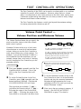
FOOT CONTROLLER OPERATIONS . . . . . . . . . . . . . . . . . . . . . . . . . . . . . . . . . 33
Volume Pedal Control — Volume Position and Minimum Volume . . . . . . . . 33
Parameter Control . . . . . . . . . . . . . . . . . . . . . . . . . . . . . . . . . . . . . . . . . . . . . . . . 34
Effect Block On/Off Control . . . . . . . . . . . . . . . . . . . . . . . . . . . . . . . . . . . . . . . 35
■
DISABLING THE EFFECT ON/OFF SWITCHING OF THE FOOT CONTROLLER
. . . 35
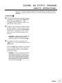
SAVING AN EFFECT PROGRAM (WRITE OPERATION) . . . . . . . . . . . . . . 37
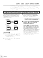
COPY AND SWAP OPERATIONS . . . . . . . . . . . . . . . . . . . . . . . . . . . . . . . . . . . . . 38
Copying One Effect Program to Another Program Number . . . . . . . . . . . . . . 38
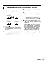
Swapping One Effect Program with Another . . . . . . . . . . . . . . . . . . . . . . . . . . 39
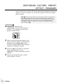
RESTORING FACTORY PRESET EFFECT PROGRAMS . . . . . . . . . . . . . . . 40
TUNER . . . . . . . . . . . . . . . . . . . . . . . . . . . . . . . . . . . . . . . . . . . . . . . . . . . . . . . . . . . . . 41
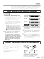
Tuning the Pitch of the Connected Instrument . . . . . . . . . . . . . . . . . . . . . . . . . 41
Changing the Standard Pitch of the Tuner Function . . . . . . . . . . . . . . . . . . . . . 41
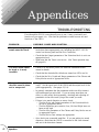
APPENDICES
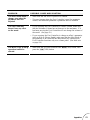
TROUBLESHOOTING . . . . . . . . . . . . . . . . . . . . . . . . . . . . . . . . . . . . . . . . . . . . . . . 42
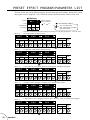
PRESET EFFECT PROGRAM/PARAMETER LIST . . . . . . . . . . . . . . . . . . . . . 44
BLANK EFFECT PARAMETER CHART . . . . . . . . . . . . . . . . . . . . . . . . . . . . . . 48
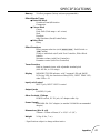
SPECIFICATIONS . . . . . . . . . . . . . . . . . . . . . . . . . . . . . . . . . . . . . . . . . . . . . . . . . . . 49
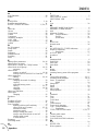
INDEX . . . . . . . . . . . . . . . . . . . . . . . . . . . . . . . . . . . . . . . . . . . . . . . . . . . . . . . . . . . . . 50

1
You are probably eager to try out your new GW10 right away and hear what it
can do, rather than have to read through a lot of instructions before you can
even get a sound out of it.
Before you do anything else, however, you should read the PRECAUTIONS
section (page 2). This tells you briefly how to care for your new GW10, how to
avoid damaging it, and how to ensure long-term, reliable operation.
Next, read the SYSTEM OVERVIEW (page 8). This provides an important
introduction to the internal organization of the GW10, enabling you to better
understand its various functions and use the device to its full potential.
To actually start using the GW10, read the GUIDED TOUR (page 12). It
guides you step-by-step in setting up your GW10, connecting it properly, and
(most importantly!) getting sound out of it. The section also introduces you to
the effect programs by letting you hear what they are capable of, and explains
how to use some of the other main functions of the device.
The REFERENCE section (page 24), on the other hand, is a comprehensive
guide to all functions. You won’t need (or want) to read through all of it at
once, but it is there for you to refer to when you need information about a
certain feature or function.
The PANEL CONTROLS AND TERMINALS (page 4) is also mainly for
reference. In general, look through this section to familiarize yourself with the
controls, and refer to it when necessary.
The INDEX in the APPENDICES section (page 50) is also very helpful. It lists
page numbers for virtually every function, feature, control and terminal found on
the GW10, and lets you find the information you need quickly and easily.
Other parts of the APPENDICES section provide additional useful information:
lists of the effect programs of the GW10, tips on troubleshooting (when some-
thing doesn’t work as expected), and other important information.
HOW TO USE THIS MANUAL (READ THIS FIRST!!)

2
PRECAUTIONS
■ USE THE CORRECT POWER SUPPLY
Power to the GW10 should be supplied only from the appropriate Yamaha
AC adaptor (the PA-3 or another adaptor specifically recommended by
Yamaha). Use of another adaptor may cause serious damage to the unit.
Also make sure that the adaptor you have is appropriate for the AC mains
supply voltage in the area where you intend to use the GW10. (The correct
input voltage is marked on the adaptor.)
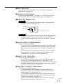
■ MEMORY BACKUP
The GW10 contains a special long-life lithium battery that retains the
contents of the internal RAM memory even when the power is turned off.
The battery should last for approximately five years from the date of
manufacture. When the backup battery power becomes too low to maintain
the memory contents, the MEMORY/TUNER Indicator lights “L” then “o”
three times when the power is turned on.
When this happens, write down all necessary settings to a piece of paper
(or on copies of the chart provided on page 48), then have the battery
replaced by qualified Yamaha service personnel as soon as possible. DO
NOT ATTEMPT TO REPLACE THE BACKUP BATTERY YOURSELF!
(Keeping records of your original settings is necessary since the memory
contents cannot be preserved when the battery is changed.)
■ AVOID EXCESSIVE HEAT, HUMIDITY, DUST AND VIBRA-
TION
Keep the unit away from locations where it is likely to be exposed to high
temperatures (such as direct sunlight) or humidity. Also avoid locations
which are subject to excessive dust accumulation or vibration which could
cause mechanical damage.
■ AVOID PHYSICAL SHOCKS
Although the GW10 has been constructed to withstand the normal rigors of
stage and studio use for optimum sturdiness and reliability, avoid subject-
ing it to strong physical shocks (such as dropping or hitting it), since this
may damage the unit. Since the GW10 is a precision-made electronic
device, also avoid applying excessive force to the various controls.
■ DO NOT OPEN THE CASE OR ATTEMPT REPAIRS OR
MODIFICATIONS YOURSELF
This product contains no user-serviceable parts. Refer all maintenance to
qualified Yamaha service personnel. Opening the case and/or tampering in
any way with the internal circuitry will void the warranty.
■ MAKE SURE POWER IS OFF BEFORE MAKING OR REMOV-
ING CONNECTIONS
Always turn the power off prior to connecting or disconnecting cables.
■ HANDLE ALL CONNECTIONS CAREFULLY
Always be careful to connect and disconnect all cables and cords by
gripping the connector itself, not by pulling on the cord.

3
■ CLEAN WITH A SOFT, DRY CLOTH
Never use solvents such as benzine or thinner to clean the unit, since these
will damage the finish. Wipe clean with a soft, dry cloth. If necessary,
use a soft, clean cloth slightly moistened only with water — making sure
to wipe the case off again with a dry cloth.
■ FOOT CONTROLLER
Do not put your fingers underneath or inside the Foot Controller pedal,
since some of the parts there have a lubricant or grease applied to them.
Doing so may not only get your hands dirty, but also remove some of the
grease necessary for smooth pedal operation.
■ ELECTRICAL INTERFERENCE
Since the GW10 contains digital circuitry, it may cause interference and
noise if placed too close to TV sets, radios or similar equipment. If such a
problem occurs, move the GW10 further away from the affected equip-
ment.

4
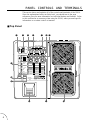
PANEL CONTROLS AND TERMINALS
This section shows and explains all of the controls and terminals of the GW10.
Since the explanations below are fairly brief, you should turn to the page
references given for more information on individual buttons and features. Refer
to this section also as necessary when using the GW10, when you need specific
information on a certain control or terminal.
■ Top Panel
GUITAR PERFORMANCE EFFECTOR
MEMORY /
BANK(HOLD)
NO
YES
WRITE
BLOCK
TYPE
ON OFF GROUP / TUNER
INPUT PEAK
DST CHO DLY
WRITE COPY SWAP
VOLUME POSITION
RELTHR NOISE GATE
MIN VOL
WAH
OD / DST
COMP
CHORUS
P . SHIFT
WAH
EQ
AMP
DELAY
DLY
CHO
DST
DST
CHO
DLY
MEMORY / TUNER
BANK
A=44✱
Hz
TIME
TYPE
LOW
SENSE
PITCH L
SPEED
SENSE
DRIVE
FEEDBACK
TONE
MID
FREQ
PITCH R
FEEDBACK
ATTACK
TYPE
MIX
HIGH
RANGE
MIX
DEPTH
OUTPUT
OUTPUT
MIX
e w qrt y
i
!0
!1
!2 o !3
u

5
q INPUT PEAK LED
For monitoring of the input signal level. (This lights intermittently at
optimum level; see page 14.)
w MEMORY/TUNER Indicator
Displays the program number. (See page 10.) During Tuner operation,
this displays the name of the note or string played. (See page 41.)
e BANK LEDs / Sharp (¶) LED
Bank LEDs
The two LEDs (green and red) indicate which of the four banks of
programs is selected. (See page 10.)
Sharp LED
The top LED also serves as a sharp indicator during Tuner operation
(functioning along with the note name shown in the MEMORY/
TUNER indicator), lighting in the case of an accidental. (See page
10.)
r ON OFF GROUP / TUNER Indicators
These LEDs serve two purposes:
• As ON OFF GROUP indicators, they correspond to the Effect Block
buttons directly below them and light to indicate which effect blocks
can be turned on and off with the Foot Controller. (See pages 19,
35.)
• As TUNER indicators (during Tuner operation), they show whether
the input signal is in tune or not; when all three indicators light
simultaneously, the signal is in tune. (See page 41.)
t WRITE, COPY, SWAP LEDs
These LEDs serve two purposes:
• As WRITE/COPY/SWAP indicators, they flash when the respective
Write, Copy, or Swap operation is active. (See pages 37–39.)
• In normal operation, these are effect block indicators, and correspond
to the Effect Block buttons directly below them and light to indicate
which effect blocks are on. (See page 18.)
y Effect Block / Group Set / Utility Buttons
These buttons serve three purposes:
• In normal operation, they correspond to the three effect blocks
(Distortion, Chorus, and Delay) and are used to turn those effect
blocks on and off. (See pages 18, 24.)
• Also, in normal operation, they are used to set the on/off group for
the effect blocks (which effect blocks will be turned on/off by press-
ing the Foot Controller). (See page 25.)
• In Write, Copy, and Swap operations, they are used to select the
respective utility operation. (See pages 37–39.)
Bank LEDs
Sharp LED
Effect program number
MEMORY / TUNER
BANK
A=44✱
Hz

6
u VOLUME POSITION Indicators
When the Foot Controller is used as a volume pedal, one of these lights to
indicate the position of the volume pedal in the effect chain. (See page 33.)
i Effect Type Indicators
These light to indicate the selected effect type in the effect block (or the
selected parameter category in the Foot Controller block, indicated by the
Foot Controller symbol). Only one of these in each block can be selected
at a time. (See pages 21, 25, 26.) When one of these indicators flashes,
the respective parameters can be edited. (See pages 20, 26.)
o Parameter Dials
For adjusting the three parameters of a selected effect. The parameters in a
single column correspond to the dial in that column.
!0 BLOCK / WRITE NO Button
This button serves several purposes:
• In normal operation, this is used to select effect blocks for editing.
(See pages 20, 25, 26.)
• When this is held down for a couple of seconds (until all LEDs go
out), it calls up the Tuner operation. Pressing it during the Tuner
operation returns to normal operation. (See page 41.)
• When this is held down and the T button is pressed, it calls up
the Write, Copy, and Swap operations. (See pages 37–39.)
• During Write, Copy, and Swap operations, this is used to cancel the
respective operation. (See pages 37–39.)
!1 TYPE / WRITE YES Button
This button serves several purposes:
• In normal operation, this is used to select effect types for editing.
(See pages 21, 25, 26.)
• Also, in normal operation (when no LEDs are flashing), this is used to
advance through the effect program numbers. (See pages 10, 11, 24.)
• In Tuner operation, this is used to adjust the tuning standard for the
note A above middle C (from 440 to 445). (See page 41.)
• When this is pressed while the B button is held down, it calls
up the Write, Copy, and Swap operations. (See pages 37–39.)
• During Write, Copy, and Swap operations, this is used to execute the
respective operation. (See pages 37–39.)
!2 MEMORY/BANK Pedal Switch
• In normal operation and in Write, Copy, and Swap operations,
pressing this steps through the effect program numbers. Holding the
switch down advances through the bank numbers. (See pages 10, 24.)
• During Tuner operation, pressing this returns to normal operation.
(See page 41.)
!3 Foot Controller
For continuous control over volume or a selected effect parameter. When
pressed firmly beyond the maximum, this turns selected effect blocks on or
off. (See pages 19, 25.) Pressing this firmly beyond the maximum and
holding it down for a couple of seconds (until all LEDs go out) calls up the
Tuner operation. (See page 41.)

7
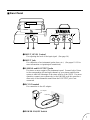
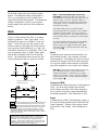
■ Rear Panel
q INPUT LEVEL Control
For adjusting the level of the input signal. (See page 14.)
w INPUT Jack
For connection of an instrument (guitar, bass, etc.). (See pages 12–13 for
more information on input/output connections.)
e L/MONO and R OUTPUT Jacks
For stereo or mono output of the instrument sound. Connect both of these
to the corresponding left and right channels of your stereo amplification
system to take full advantage of the stereo effects of the GW10. For mono
operation, connect your system only to the L/MONO jack; this provides a
mono mix of the instrument sound when the R OUTPUT jack is not
connected.
r DC IN Terminal
For connection to the AC adaptor.
t POWER ON/OFF Switch
AC adaptor
Cable clip
DC IN
ON / OFF
POWER
INPUT
R L / MONO
LEVEL
OUTPUT
q w r te

8
SYSTEM OVERVIEW
This section provides a brief overview of the GW10 — the basic structure of its
various functions and the memory system. Once you gain a general understand-
ing of the internal workings of the GW10 as given here, you’ll have the tools for
taking full advantage of its features.
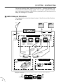
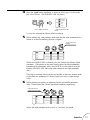
The diagram below shows the internal system of the effects and other functions
of the GW10.
■ GW10 Internal Structure
ON OFF GROUP / TUNER
INPUT PEAK
MEMORY / TUNER
BANK
A=44✱
Hz
OD/DST
Overdrive
Crunch
Distortion
COMP
Guitar
MULTI-EFFECT SECTION
FOOT PEDAL CONTROL AUTOMATIC TUNER
DST CHO DLY
Noise Gate
INPUT
INPUT
LEVEL
INPUT
PEAK
L/MONO
R
OUTPUT
Amplifiers
Built-in pedal switch allows
on/off control of effect
groups.
When the Distortion
block is on and
OD/DST is active,
Noise Gate is on;
when COMP is active,
Noise Gate is off.
CHORUS
P.SHIFT
WAH *
EQ
AMP
DELAY
Volume pedal
MIN VOL
Distortion block
parameter
control
Wah pedal
Chorus block
parameter
control
Delay Mix
parameter control
Volume pedal
MIN VOL
Volume
pedal
MIN VOL
THR REL
Tuner
switch
*
DST
CHO
DLY
Noise Gate
WAH
THR REL
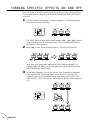
When Wah is selected in the Chorus block and the OD/DST is active, the order of the effects
changes as shown here:

9
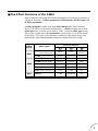
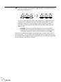
Keep in mind as you use the GW10 that the structure of its effects is basically in
a four-part hierarchy: 1) Effect programs, 2) Effect blocks, 3) Effect types, and
4) Effect parameters.
An effect program is made up of three effect blocks and a Foot Controller
block, all of which can be used simultaneously. A block includes one or more
effect types, one of which can be used at a time. And each effect type (except
Noise Gate) is made up of three parameters, which allow you to set the sound
of the effect. The logic of this structure is reflected in the panel layout, with
effect blocks, types and parameters printed in a matrix from left to right.
■ The Effect Structure of the GW10
OD/DST (Overdrive/
Crunch/Distortion)
COMP (Compressor)
CHORUS
P.SHIFT (Pitch Shift)
WAH
EQ (Equalizer)
AMP (Amp Simulator)
DST
CHO
Effect
Blocks
Effect Types
Effect Parameters*
OUTPUT
OUTPUT
DEPTH
MIX
RANGE
HIGH
MIX
TYPE
ATTACK
FEEDBACK
PITCH R
FREQ
MID
TONE
DRIVE
SENSE
SPEED
PITCH L
SENSE
LOW
TYPE
DELAYDLY
TIME FEEDBACK MIX
(* arranged in columns corresponding to their controlling parameter dials)

10
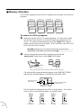
■ Memory Structure
The 20 effect programs of the GW10 are organized in four banks, each with five
programs.
Program 5
Bank 1
Program 4
Program 3
Program 2
Program 1
Program 5
Bank 2
Program 4
Program 3
Program 2
Program 1
Program 5
Bank 3
Program 4
Program 3
Program 2
Program 1
Program 5
Bank 4
Program 4
Program 3
Program 2
Program 1
To select an effect program:
1
Make sure that the GW10 is in normal operation. (In other words, make
sure that the Tuner function or the Write/Copy/Swap operations are not
active.) To return to normal operation, press the B(NO) button or
simply turn the power off and on again. In this condition, some LEDs will
be lit, but none will be flashing.
NOTE ■
Alternatively, you can exit the Tuner function by pressing the
M
Pedal Switch or the Foot Controller.
■
2
Advance through the various effect programs by pressing the
M Pedal Switch or the T(YES) button.
NO
YES
WRITE
BLOCK
TYPE
The selected effect program number appears in the MEMORY/TUNER
indicator and the bank number is indicated by the BANK LEDs.
The four banks are indicated by the LEDs as shown below. (For instruc-
tions on how to select different banks, see step #3 below.)
Shows the current
bank number
Shows the current effect
program number
MEMORY / TUNER
BANK
A=44✱
Hz
Each press of either of these advances to the next effect program.
Bank 1 Bank 2 Bank 3 Bank 4
both LEDs off green LED lit red LED lit both LEDs lit
BANK BANK BANK BANK

11
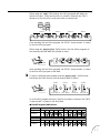
When using the T(YES) button, the effect programs and banks are
selected in order. After the last effect in a bank is selected, the GW10
advances to the first effect in the next bank, as shown here:
NO
YES
WRITE
BLOCK
TYPE
Bank 1 Bank 2 Bank 3 Bank 4
After reaching the last effect program, the GW10 “wraps around” to return
to the first effect program.
When using the M Pedal Switch, only the effect programs of
the currently selected bank are selected in order.
After reaching the last effect program, the GW10 “wraps around” to return
to the first effect program in the bank.
3
To select a different bank number with the M Pedal Switch,
hold down the Pedal Switch until the desired bank is shown.
Bank 1
both LEDs off
Bank 2
green LED lit
Bank 3
red LED lit
Bank 4
both LEDs lit
BANK BANK BANK BANK
As with effect program selection, after the last bank is selected, the GW10
“wraps around” to return to the first bank.
● Bank/Program Indications
Program No.
Display
Bank No.
1
12
234512345
1
34
234512345
Program No.
Display
Bank No.

12
Guided Tour
Guided Tour
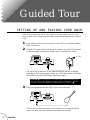
Once you’ve taken your GW10 out of the box and are ready to use it, you’ll
have to make a few connections and follow some simple instructions on setting
it up.
1
First, make sure that the power switch on the GW10 is off before making
ANY connections.
2
Plug the DC output cable from the power adaptor into the DC IN terminal
on the rear panel, then plug the adaptor into a convenient AC outlet.
SETTING UP AND PLAYING YOUR GW10
The cable clip located next to this terminal helps to prevent accidental
unplugging of the power supply during use. Wrap the adaptor cord firmly
around the clip (see the Rear Panel illustration, page 7).
CAUTION! ■
Do not attempt to use a different AC adaptor with the GW10.
Also, be sure to check whether the rated voltage is appropriate. (See the
precaution “USE THE CORRECT POWER SUPPLY” on page 2.)
■
3
Plug your instrument into the INPUT jack on the rear panel.
For the sake of these instructions, we’ll assume you’re using an electric
guitar; however, most any electronic instrument can be used.
INPUT
DC IN
ON / OFF
POWER
INPUT
R L / MONO
LEVEL
OUTPUT
DC IN
ON / OFF
POWER
INPUT
R L / MONO
LEVEL
OUTPUT
DC IN
AC outlet

13
Guided Tour
NOTE ■
You should be careful if you are connecting a synthesizer or
electronic keyboard; generally their output level is much higher than that of
a guitar and the input level, as well as the volume control on the keyboard,
should be turned down accordingly (see step #4 below).
■
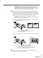
4
Connect the GW10 output or outputs to your amplifier/speaker system.
Before you do this, however, make sure that the power on the system is
first turned off and all volume controls are set to zero — this includes the
guitar controls, the INPUT LEVEL and the Foot Controller on the GW10
itself, and the volume on the connected amp (or mixing console).
NOTE ■
To set the INPUT LEVEL on the GW10 to the minimum, turn the
control all the way counterclockwise.
■
Two example connection systems are shown below. Use the one which
most closely resembles your own system.
EX.1
Here, the left and right outputs of the GW10 are sent to two
separate guitar amps.
If you are using a single guitar amp, connect it to the L/MONO OUTPUT
jack.
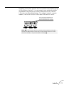
EX. 2
EX.2
In this system for studio recording applications, the left and right
channels of the instrument/effect sound go into separate mixer
channels. For best results with this setup, use the Amp Simulator
effect in the Chorus block (see page 30).
5
Turn on the power of all the equipment, starting with the GW10, and
turning on the connected amplifier last.
DC IN
ON / OFF
POWER
INPUT
R L / MONO
LEVEL
OUTPUT
L/MONOR
DC IN
ON / OFF
POWER
INPUT
R L / MONO
LEVEL
OUTPUT
L/MONOR

14
Guided Tour
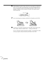
6
While playing your guitar, bring up the level on your guitar and adjust the
INPUT LEVEL control on the rear panel of the GW10. Increase the level
slowly as you play the guitar while looking at the INPUT PEAK LED on
the panel. When you play your guitar the loudest, the indicator should
light intermittently.
INPUT PEAK
ON OFF GROUP / TUNER
WRITE COPY SWAP
7
Next, slowly bring the volume up with the Foot Controller on the GW10.
8
Now that you’ve properly set the level on the GW10, slowly bring up the
other volume controls to suitable levels — starting with the amp.
If you’ve followed all these instructions carefully, you should now be able
to hear your guitar sound processed by the effects of the GW10.

15
Guided Tour
THE EFFECTS OF THE GW10
The GW10 is equipped with a comprehensive set of effects designed specifically
for the guitar player. You can switch these effects on and off as needed and
adjust them quickly and easily from the panel controls.
There are three groups or “blocks” of effects — Distortion, Chorus and Delay —
plus a special Foot Controller block that includes a Noise Gate effect and the
Foot Controller settings. The Distortion block includes Crunch, Overdrive and
Compressor effects, while the Chorus block also features Pitch Shift, Wah,
Equalizer, and Amp Simulator effects.
(Refer to the EFFECTS AND PARAMETERS section, page 27, for more
detailed descriptions and explanations of these effects.)
With these three effect blocks, used individually or simultaneously, the GW10
has all you need to augment your sound, whatever the application. Plus, flexible
effect bypass (on/off) functions give you even more realtime control over the
sound.

16
Guided Tour
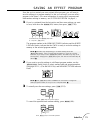
PLAYING WITH THE PRESET EFFECTS
Now that you’ve set up your GW10 and are ready to use it, let’s try playing
with some of the preset effects. (If you haven’t already done so, read through
the SYSTEM OVERVIEW section on pages 8–11 for information on the basic
structure of the GW10 and how to select effect programs.)
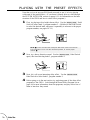
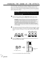
1
First, try playing with a bright chorus effect. Use the M Pedal
Switch to select bank 3, program number 5. (Hold down the Pedal Switch
to select the desired bank, and press it repeatedly to advance to the proper
program number; see pages 10–11.)
NOTE ■
For this and the other examples that follow, make sure that the
Foot Controller is at or near the maximum position, to ensure proper
volume.
■
2
Now, try a heavy distortion sound. Use the M Pedal Switch
again, this time selecting bank 2, program number 1.
3
Next, let’s call up an interesting delay effect. Use the M
Pedal Switch to select bank 1, program number 3.
4
Before going on to the next section, try exploring some of the other effect
programs of the GW10. Look through the Preset Effect Program list on
page 44 for more information about the programs, and play with a few of
them to hear how they sound.
MEMORY / TUNER
BANK
A=44✱
Hz
MEMORY / TUNER
BANK
A=44✱
Hz
La pagina sta caricando ...
La pagina sta caricando ...
La pagina sta caricando ...
La pagina sta caricando ...
La pagina sta caricando ...
La pagina sta caricando ...
La pagina sta caricando ...
La pagina sta caricando ...
La pagina sta caricando ...
La pagina sta caricando ...
La pagina sta caricando ...
La pagina sta caricando ...
La pagina sta caricando ...
La pagina sta caricando ...
La pagina sta caricando ...
La pagina sta caricando ...
La pagina sta caricando ...
La pagina sta caricando ...
La pagina sta caricando ...
La pagina sta caricando ...
La pagina sta caricando ...
La pagina sta caricando ...
La pagina sta caricando ...
La pagina sta caricando ...
La pagina sta caricando ...
La pagina sta caricando ...
La pagina sta caricando ...
La pagina sta caricando ...
La pagina sta caricando ...
La pagina sta caricando ...
La pagina sta caricando ...
La pagina sta caricando ...
La pagina sta caricando ...
La pagina sta caricando ...
La pagina sta caricando ...
La pagina sta caricando ...
La pagina sta caricando ...
-
 1
1
-
 2
2
-
 3
3
-
 4
4
-
 5
5
-
 6
6
-
 7
7
-
 8
8
-
 9
9
-
 10
10
-
 11
11
-
 12
12
-
 13
13
-
 14
14
-
 15
15
-
 16
16
-
 17
17
-
 18
18
-
 19
19
-
 20
20
-
 21
21
-
 22
22
-
 23
23
-
 24
24
-
 25
25
-
 26
26
-
 27
27
-
 28
28
-
 29
29
-
 30
30
-
 31
31
-
 32
32
-
 33
33
-
 34
34
-
 35
35
-
 36
36
-
 37
37
-
 38
38
-
 39
39
-
 40
40
-
 41
41
-
 42
42
-
 43
43
-
 44
44
-
 45
45
-
 46
46
-
 47
47
-
 48
48
-
 49
49
-
 50
50
-
 51
51
-
 52
52
-
 53
53
-
 54
54
-
 55
55
-
 56
56
-
 57
57


Yamaha GW10 Manuale del proprietario
- Categoria
- Strumenti musicali
- Tipo
- Manuale del proprietario
in altre lingue
- English: Yamaha GW10 Owner's manual
- français: Yamaha GW10 Le manuel du propriétaire
- español: Yamaha GW10 El manual del propietario
- Deutsch: Yamaha GW10 Bedienungsanleitung
- русский: Yamaha GW10 Инструкция по применению
- Nederlands: Yamaha GW10 de handleiding
- português: Yamaha GW10 Manual do proprietário
- dansk: Yamaha GW10 Brugervejledning
- čeština: Yamaha GW10 Návod k obsluze
- polski: Yamaha GW10 Instrukcja obsługi
- svenska: Yamaha GW10 Bruksanvisning
- Türkçe: Yamaha GW10 El kitabı
- română: Yamaha GW10 Manualul proprietarului
Documenti correlati
-
Yamaha VP-500 Manuale utente
-
-
-
-
-
-
-
-
-