
INSTALLATION AND
MAINTENANCE
OF
WASHING MACHINE 2-15
TUMBLE DRYER 16-34
INDEX 36
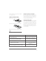
WA SL3 M
TK SL3 M
TA SL3 M

2
SAFETY 3
Transit screws
General
Child lock on Start/Stop button
Door
Overfill cut-out
Packaging
Transport/Winter storage
Scrapping
PARTS OF THE WASHING MACHINE 4
TECHNICAL INFORMATION 4–5
Technical data
Programme cycles
MECHANICAL INSTALLATION 6–8
Transit screws
Positioning the washing machine
Adjusting the feet
Connecting to water supply
Water intake – mixed or cold water
Connecting to drain
ELECTRICAL INSTALLATION 9
Electrical installation
Connecting to coin mechanism
CONTENTS – WASHING MACHINE
CHANGING SETTINGS 10–11
Language
Locking the programme
Wash temperature, C or F
Changing preset wash temperature
Child lock
MAINTENANCE 12–13
Emptying/cleaning trap and drain pump
Inspection holes under drum paddles
Cleaning the detergent drawer
Cleaning the outside of the machine
In areas with hard water
TROUBLESHOOTING 14–15
Door will not open
Machine will not start
Error messages
The display is lighting when a program
me is selected, but no characters or
digits are shown
Wrong language displayed
WASHING MACHINE CONTENTS

3
GENERAL
• Read and keep this manual!
• Any electrical work or plumbing must be car-
ried out by qualified tradesmen.
• Remove the transit screws before you use the
machine, see Mechanical installation.
CHILD LOCK ON BUTTON
To prevent accidental button pushes on the
button you can activate the child lock
function. The
button then must be held
in for three seconds to activate the machine.
DOOR
The door is opened electrically, so it cannot be
opened until the machine is connected to the
electrical supply! The door can however be ope-
ned in an emergency, see Troubleshooting.
OVERFILL CUT-OUT
If the water level in the machine rises above
normal the overfill cut-out shuts off the water
intake and starts pumping out the water. The
programme resumes when the water level has
dropped.
PACKAGING
Recycle the packaging according to recommen-
dations in your area.
TRANSPORT/WINTER STORAGE
If you intend to transport the machine or store
it over winter in unheated premises, empty the
trap and the drain pump, see the chapter on
Maintenance.
Any questions? Call service.
SCRAPPING
At the end of its life the machine must be disa-
bled before being scrapped.
Contact your local recycling centre to find
out where to dispose of it or recycle it.
The machine has been built and marked to
facilitate recycling.
SAFETY
SAFETY WASHING MACHINE

4
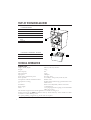
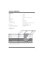
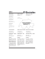
TECHNICAL DATA
Height, Width, Depth: 850 mm, 595 mm, 585 mm.
Weight: 73 kg.
Drum capacity: 50 l.
Max wash load: 6.0 kg.
Spin speed: 1200 rpm.
Power rating and element power: See rating plate.
Water pressure: 0.1–1 MPa, 1–10 kp/cm2, 10–100 N/cm2.
Composition of drum and fluid container: Stainless steel.
Composition of casing: Powder-painted and hot-dip galvanized sheet steel
or stainless steel.
Installation: Static on four adjustable, rubber-covered feet.
Water supply: 1.5 m PEX hose.
Drain: 1.7 m polypropylene hose (pump) or 0.4 mm EPDM
rubber hose (valve).
This machine is approved for all UK applications as suitable for Category 5.
Product is listed in the WRAS regulations advisory scheme directory and is suitable for direct
connection to mains drinking water.
No special plumbing arangements e.g. break tanks are required.
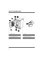
1. DETERGENT DRAWER
2. POWER SWITCH
3. PROGRAMME PANEL
4. RATING PLATE
5. DOOR-DRAIN PUMP/EMERGENCY OPEN
6. DRAIN PUMP/EMERGENCY OPEN (BEHIND
FLAP)
7. DOOR
1. DETERGENT COMPARTMENT – PRE-WASH
2. DETERGENT COMPARTMENT – MAIN WASH
3. FABRIC CONDITIONER COMPARTMENT
PARTS OF THE WASHING MACHINE
TECHNICAL INFORMATION
WASHING MACHINE PARTS OF THE WASHING MACHINE/ TECHNICAL INFORMATION
1
7
6
5
8
2
4
3
1 2 3
4
5
6
7
1
2
3

5
TECHNICAL INFORMATION WASHING MACHINE
80
110
54
40
25
20
25
4
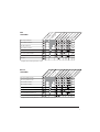
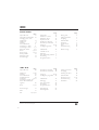
P1 Heavy wash 90°C
P2 Normal wash 60°C
P3 Light wash 60°C
P4 Normal wash 40°C
P5 Synthetic wash 40°C
P6 Super quick wash 40°C
P7 Wool/hand wash 30°C (1)
P8 Spin
(1) High water level and gentle motor action.
EURO
PROGRAMMES
Max .load
Pre wash
Rinse
Spin
Rinse
Spin
Rinse
Spin
Length (appr. min)
Main wash
90
86
54
40
25
20
25
11
P1 Heavy wash 90°C (2)
P2 Heavy wash 80°C (2)
P3 Normal wash 60°C
P4 Normal wash 40°C
P5 Synthetic wash 40°C
P6 Super Quick wash 40°C
P7 Wool/hand wash 30°C (1)
P8 Rinse
MEDICAL
PROGRAMMES
(1) High water level and gentle motor action. (2) Cannot be interrupted.
Max .load
Pre wash
Rinse
Spin
Rinse
Spin
Rinse
Spin
Length (appr. min)
Main wash

6
WASHING MACHINE MECHANICAL INSTALLATION
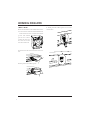
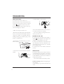
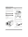
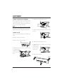
MECHANICAL INSTALLATION
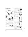
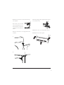
TRANSIT SCREWS
Before the machine can be used the three trans-
it screws must be removed as described below.
Each transit screw has a washer and a rubber
spacer. The rubber
spacers are used to
protect the screw ho-
les after the screws
have been removed.
1. First unscrew the screw and remove the was-
her.
2. Then pull out the rubber spacer.
2
1
3. Finally, refit the rubber spacers to cover the
transit holes.

7
595 mm
585 mm
8
50 m
m
1
7
6
5
8
2
4
3
min 600 mm
min 850 mm
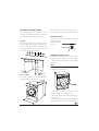
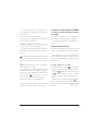
POSITIONING THE WASHING MACHINE
The washing machine can be built-in or free-
standing. It should be positioned so that there
is an electrical socket within easy reach.
A. Built-in
The washing machine can be built in under a
worktop with a working height of 850–900 mm.
Leave a 5 mm gap around the machine. This
also applies between the rear edge of the top
the machine and the wall behind.
B. Free-standing
The washing machine can be placed alongside
or underneath the tumble dryer.
The machine can be anchored to the floor, see
enclosed bag containing instructions and parts.
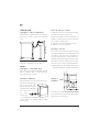
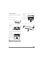
ADJUSTING THE FEET
Adjust the feet so that the machine is level and
steady on the floor.
Tighten the lock-
ing nuts.
CONNECTING TO WATER SUPPLY
The machine should be connected to the water
supply by someone who has the necessary skill.
The machine is connected using the supplied
inlet hose.
NOTE!
It is important that you use the inlet hose that
is supplied, not an old hose.
The water pressure must be 0.1–1 MPa
(about 1–10 kp/cm
2
; 10–100 N/cm
2
).
The water supply pipe must be fitted with a
shut-off valve.
If the supply pipe has just been installed we
recommend that it is flushed out thoroughly
Locking nut
MECHANICAL INSTALLATION WASHING MACHINE

8
600-900 mm
first to remove any dirt. Otherwise this could
clog the intake filter in the machine and block
the water supply.
WATER INTAKE – MIXED OR COLD WATER
On delivery the machine is set to use mixed hot
and cold water. The machine can be reset to use
only cold water or hot water.
To change the water intake setting, do as
follows:
Switch off the power switch, , then switch
it on again so that the machine is in start-up
mode.
Press the
8
button five times, then press
the
4
button five times. You have to comple-
te these ten button presses within fifteen se-
conds.
Within three seconds of pressing the
4
but-
ton for the fifth time you must then select the
type of water intake you want by pressing the
6
or
8
buttons.
6
to use cold water only (C).
8
to use mixed hot and cold water (E).
A letter C near the bottom right of the dis-
play shows that cold water is being used and
the letter E indicates mixed hot and cold.
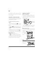
CONNECTING TO THE DRAIN
Machine with drain pump
The machine is supplied with a drain hose al-
ready fitted and this should be connected to a
laundry sink, or the like, at a height of 600–900
mm above the floor.
The lower height (600 mm) is always prefera-
ble. Make sure the drain hose is not kinked.
Machine with drain valve
An outlet hose is supplied with the machine.
This must be connected to the outlet on the
machine and
empty into a
floor drain
or gutter
drain.
NOTE!
The end of the outlet hose must be lower than
the lowest
point of the
outlet valve.
WASHING MACHINE MECHANICAL INSTALLATION

9
ELECTRICAL INSTALLATION
ELECTRICAL INSTALLATION
The washing machine must be connected using
a permanently installed cable through an isola-
ting switch by a qualified electrician.
Power supply
The machine is supplied, depending on market,
for one of the following supplies (see rating
plate):
A. 3-phase, 400V, 50 Hz supply, 10 A.
B. Single-phase, 230 V, 50 Hz supply, 13/16 A.
C. Single-phase, 230 V, 50 Hz supply, 10 A.
If an earth leakage circuit breaker is fitted it
must be of type A.
Reconfiguration
The machine can be reconfigured. The machi-
ne should be reconfigured as shown in the wi-
ring diagram underneath the top panel of the
machine.
NOTE!
Electrical connection /reconfiguring must be car-
ried out by a qualified electrician.
ELECTRICAL INSTALLATION WASHING MACHINE
CONNECTING TO A COIN MECHANISM
Connection to a coin mechanism must be car-
ried out by a qualified electrician.
A special connecting cable is required to con-
nect the machine to a coin mechanism. This
can be ordered as a spare part, art. no. 92 090
95.
Recommendations for choice of coin mechanism
The connecting cable (92 090 95) supplies the
coin mechanism with power (230 V). The coin
mechanism must be able to short-circuit two
signal leads for a period of time (around 0–10
minutes). This is so that the user has time to
load the laundry, select the programme and start
the programme after inserting the coins.

10
LANGUAGE
You can change the language of the displayed
text.
The languages you can choose from are Dansk,
Deutsch, English, Espanol, Français, Italiano,
Nederlands, Norsk, Portugués, Suomi and
Svenska.
To change language do as follows:
Switch off the power switch, , then switch it
on again so that the machine is in start-up mode.
Press the
8
button five times, then press
the
1
button five times. You have to comple-
te these ten button presses within fifteen se-
conds.
Within three seconds of pressing the
1
but-
ton for the fifth time you should then select the
language you want by pressing the
6
or
7
buttons.
LOCKING A PROGRAMME
If for some reason you want to limit the number
of programmes that can be used you can lock
one or more programmes.
No characters or digits are shown on the dis-
play when a locked programme is selected.
To lock or unlock a programme, do as follows:
Switch off the power switch, , then switch it
on again so that the machine is in start-up mode.
Press the
8
-button five times, then press
the
7
-button five times. You have to com-
plete these ten button presses within fifteen se-
conds.
Within three seconds of pressing the
7
-
CHANGING SETTINGS
button for the fifth time you should hold in the
programme button for the programme you want
to lock for 5-10 seconds until the information
in the display starts flashing.
Then you can lock the programme by relea-
sing the programme button and pressing the
-button once.
Do the same to unlock the programme.
WASH TEMPERATURE - CENTIGRADE OR FAHRENHEIT
You can change the way the temperature is dis-
played from centigrade (C) to Fahrenheit (F).
To change the temperature display, do as follows:
Switch off the power switch, , then switch it
on again so that the machine is in start-up mode.
Press the
8
button five times, then press
the
2
button five times. You have to comple-
te these ten button presses within fifteen se-
conds.
Within three seconds of pressing the
2
button for the fifth time you should then press
the
6
or
7
buttons to select centigrade
(C) or Fahrenheit (F).
CHANGING PRESET WASH TEMPERATURE
You can change the preset wash temperatures
for each of the programmes. The temperatures
you can choose from are:
Heavy wash - C, 30, 35, …, 85, 90ºC.
Normal wash - C, 30, 35, …, 85, 90ºC.
Light wash - C, 30, 35, …, 85, 90ºC.
Synthetic wash - C, 30, 35, …, 85, 90ºC.
Super quick wash - C, 30, 35, …, 85, 90ºC.
Wool/hand wash - C, 30, 35, 40ºC.
WASHING MACHINE CHANGING SETTINGS

11
CHANGING SETTINGS WASHING MACHINE
If you choose C, the wash temperature will
be the same as the intake water temperature.
To change the wash temperature, do as follows:
Switch off the power switch, , then switch it
on again so that the machine is in start-up mode.
Press the
8
button five times, then press
the
6
button five times. You have to com-
plete these ten button presses within fifteen se-
conds.
Press the programme button,
1
-
8
, to
select the programme you want to change the
wash temperature for.
Then use buttons
6
(reduce time) and
7
(increase time) to choose the wash tem-
perature. As you scroll through to the chosen
temperature it appears at the bottom of the
display alongside the
symbol.
When your chosen wash temperature appears
press the
8
button again to confirm your
choice.
CHILD LOCK ON BUTTON
To prevent accidental button pushes on the
button you can activate the child lock
function. The
button then must be held
in for three seconds to activate the machine.
To switch the child lock on or off, do as follows:
Switch off the power switch, , then switch it
on again so that the machine is in start-up mode.
Press the
8
button five times, then press
the
3
button five times. You have to comple-
te these ten button presses within fifteen se-
conds.
Within three seconds of pressing the
3
but-
ton for the last time you must then press the
6
or
7
button to choose whether you
want the child lock on or off.
Press
7
to activate the child lock.
Press
6
to disable the child lock.

12
2
1
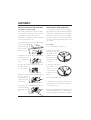
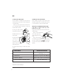
MAINTENANCE
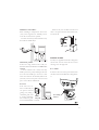
EMPTYING/CLEANING TRAP AND DRAIN PUMP
(only machines with drain pump)
The washing machine has a trap that is desig-
ned to catch coins, hair clips, etc. To clean the
trap and the drain pump, do as follows:
1. Make sure the machine is empty of water and
that the power switch is off.
2. Open the flap that conceals the drain pump
at the bottom
left of the mach-
ine. Use a screw-
driver as shown.
3. Pull the hose off the spigot inside the flap
and drain the water
into a suitable con-
tainer.
4. Open the pump by turning the cap anti-
clockwise. Remove
the cap and trap.
5. Remove any objects and waste from the pump
housing. Check
that the pump im-
peller at the back
rotates freely.
6. Screw the cap and trap back into place, re-
connect the drain
hose and close the
flap.
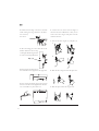
INSPECTION HOLES UNDER DRUM PADDLES
If you think that an item such as a nail, paper-
clip, hair clip or the like has fallen through the
wash drum you should inspect the outer drum
through the inspection holes in the paddles.
Items such as this can rust and produce stains
on clothes. Nails and other sharp items could
tear clothes.
Do as follows
1. Use a screwdriver or similar tool.
2. Insert the screwdriver
through the hole in
the middle of the
paddle and lever
the handle of the
screwdriver gently
to the left.
3. Grasp the rear edge of
the paddle cover
with your other
hand and pull it
towards you as
shown.
4. Lift off the paddle cover.
5. Examine the space between the inner and
outer drum as you turn the inner drum. Rem-
ove any items you see.
6. Engage the paddle cover in its locating holes
with the F marking nearest you. Make sure that
all the clips engage in their holes in the drum.
WASHING MACHINE MAINTENANCE

13
Push the paddle cover away from you until it is
in its original position.
CLEANING THE DETERGENT DRAWER
Pull the drawer out as far as it will go.
Then lift it upwards and outwards as shown.
Wash and wipe clean the detergent compart-
ments.
NOTE!
Do not put the detergent drawer in a dishwash-
er!
CLEANING THE OUTSIDE OF THE MACHINE
Clean the outside and the programme panel
using mild detergent. Do not use abrasives or
solvents as they may damage the machine. Do
not spray the machine with water.
IN AREAS WITH HARD WATER
If the machine is installed in an area with hard
water a greyish white deposit may appear on
the wash drum. To remove this, empty a 20
gram packet of citric acid into the wash drum
and run a Normal wash programme at 85ºC.
You will find citric acid on the spice shelf at
your supermarket.
MAINTENANCE MAINTENANCE INTERVAL
Trap and drain pump 12 times a year or each 25 cycle
Inspection holes under drum paddles Twice a year
or each 150 cycle
Cleaning detergent drawer 12 times a year or each 25 cycle
Cleaning outside of machine As necessary or when cleaning
laundry room.
Hard water (greyish white deposit in drum) Twice a year
or each 150 cycle
Maintenance chart for washing machine.
MAINTENANCE WASHING MACHINE

14
TROUBLESHOOTING
DOOR WILL NOT OPEN
1. Check that the power switch is on.
2. Has there been a power cut? Check the fuses
in the fuse box. The door cannot be opened
with the
button if there is no power.
3. If everything else fails the door can be ope-
ned in an emergency as follows:
• Make sure the power switch is off.
• Machines with a drain pump: First check that
there is no water left in the machine. If there is,
empty the machine as described under the
heading Checking trap and drain pump, in the
chapter on Maintenance.
• Open the flap at the bottom left. Use a screw-
driver as shown.
• Unscrew the screw that holds the red plastic
handle.
• Pull the handle to open the door.
• Press the handle back into its recess and secu-
re it with the screw. Close the flap.
If you have problems opening the door nor-
mally again, call service.
MACHINE DOES NOT START
1. Is the door shut properly? Push it firmly. A
flashing symbol appears in the display if the
machine is started with the door open.
2. Check if the child lock is activated. To start
the tumble dryer when the child lock is acti-
vated, hold in the start button for 3 seconds.
See Changing settings.
3. Is there power to the machine. Check the
fuse box.
ERROR MESSAGES
The character display shows whether a fault has
occurred during the programme. To cancel an
error message after the fault has been corrected
as described below, switch off the machine or
change the programme.
You can check and fix some faults yourself:
Problem emptying. Machine not emptying pro-
perly. Check:
– that nothing has got stuck in the drain hose
outlet.
WASHING MACHINE TROUBLESHOOTING

15
– that the drain pump is not blocked by a fo-
reign object. Clean the pump, see chapter on
Maintenance.
– that the drain hose is not kinked.
After doing this, run programme P8. If there is
still a problem, call service.
Machine not filling. Fault in water supply, check:
- is the tap on the water pipe open?
- is the filter in the machine’s water intake bloc-
ked? Turn off the tap. Unscrew the hose and
check.
is flashing in the bottom right corner of the
display. The programme has tried to start but
the door is open. Close the door and start again.
0000 is flashing at the top right of the display.
The machine has not spun.
1. The machine has a built-in imbalance sensor
that reduces the speed or prevents spinning if
the load is poorly distributed. Switch off the
power switch,
, then switch it on again.
Open the door and redistribute the load.
2. After doing this, run programme P8.
If there is some other fault, call service and say
which error message appears in the display.
THE DISPLAY IS LIGHTING WHEN A PROGRAMME
IS SELECTED, BUT NO CHARACTERS OR DIGITS
ARE SHOWN
No characters or digits are shown on the dis-
play when a locked programme is selected.
To unlock a programme, see Changing set-
tings.
WRONG LANGUAGE DISPLAYED
If the display language has changed for some
reason you can go back to the original langua-
ge.
The languages you can choose between are
Dansk, Deutsch, English, Espanol, Français,
Italiano, Nederlands, Norsk, Portugués, Suomi
and Svenska.
To change language do as follows:
Switch off the power switch, , then switch it
on again so that the machine is in start-up mode.
Press the
8
button five times, then press
the
1
button five times. You have to comple-
te these ten button presses within fifteen se-
conds.
Within three seconds of pressing the
1
but-
ton for the fifth time you should then select the
language you want by pressing the
6
or
7
buttons.
TROUBLESHOOTING WASHING MACHINE

16
SAFETY 17
General
Using the dryer first time
Child lock on Start/Stop buttons
Thermal cut-out
Float
Door
Packaging
Scrapping
PARTS OF THE TUMBLE DRYER 18
TECHNICAL INFORMATION 19
Technical data
Programme cycles
MECHANICAL INSTALLATION 20–25
Positioning the tumble dryer
Adjusting the feet
Condensed water
Venting
Reversing the door
ELECTRICAL INSTALLATION 26
Electrical installation
Connecting to coin mechanism
CONTENTS - TUMBLE DRYER
CHANGING SETTINGS 28
Language
Locking the programme
Child lock
MAINTENANCE 30–32
Cleaning the outside of the machine
Cleaning the fan
Cleaning the condenser
Cleaning the lint filter
In areas with hard water
Emptying the condensation water tank
TROUBLESHOOTING 33–34
Machine will not start
Thermal cut-out
Drying takes too long
Error messages
The display is lighting when a program
me is selected, but no characters or
digits are shown
Wrong language displayed
TUMBLE DRYER CONTENTS

17
GENERAL
• Read and keep this manual!
• Any electrical work must be carried out by a
qualified electrician.
USING THE DRYER FOR THE FIRST TIME
When you start the dryer for the first time, or if
it has not been used for a long time, you may
hear a faint clunking noise. This is entirely nor-
mal and will disappear after a few cycles.
CHILD LOCK ON BUTTON
To prevent accidental button pushes on the
button you can activate the child lock
function. The
button then must be
held in for three seconds to activate the mach-
ine.
THERMAL CUT-OUT
The tumble dryer is protected by a thermal cut-
out. This switches off the machine if it gets too
hot.
FLOAT (only applies to condenser dryer)
A float switches off the machine if there is a
blockage in the condensed water hose.
CAUTION!
During the programme, the back of the tumble
dryer will get very hot. Leave the machine to
cool completely before touching the back.
SAFETY
DOOR
The tumble dryer has a magnetic lock, which
makes it easy to open the door from the outside
or inside. The door is fitted with a switch that
automatically switches off the tumble dryer
when the door is opened. The tumble dryer
does not start automatically when the door is
closed (for example if a child pulls the door
closed from the inside).
PACKAGING
Recycle the packaging according to recommen-
dations in your area.
SCRAPPING
At the end of its life the machine must be disa-
bled before being scrapped.
Contact your local recycling centre to find
out where to dispose of it or recycle it.
The machine has been built and marked to
facilitate recycling.
SAFETY TUMBLE DRYER

18
1
7
6
5
8
2
4
3
1. LINT FILTER HOLDER
2. RATING PLATE
3. CONDENSATION WATER TANK –
CONDENSER TUMBLE DRYERS ONLY
4. PANEL
4
1
2
5
7
8
5. DOOR
6. FAN (BEHIND FRONT PANEL)
7. CONDENSER – ONLY CONDENSER TUMBLE
DRYERS (BEHIND FRONT PANEL)
8. LINT FILTER
6
PARTS OF THE TUMBLE DRYER
TUMBLE DRYER PARTS OF THE TUMBLE DRYER
3

19
TECHNICAL INFORMATION
TECHNICAL DATA
Height: 850 mm.
Width: 595 mm.
Depth: 585 mm.
Weight: 39 kg (vented) / 47 kg (condenser).
Drum capacity: 111 l.
Drying capacity: 6.0 kg.
Speed: 52 rpm.
Power rating: See rating plate.
Composition of drum: Stainless steel.
Composition of casing: Powder-painted and hot-dip galvanized sheet
steel or stainless steel.
Installation: Stacked, free-standing or built-in.
Drain (condenser tumble dryer): 2.0 m EPDM rubber hose.
Vent hose (venting tumble dryer): 3.0 m PVC.
PROGRAMME CYCLES
TECHNICAL INFORMATION TUMBLE DRYER
P1 Extra dry
P2 Dry
P3 Normal dry
P4 Iron dry
P5 Extra dry
P6 Dry
P7 Normal dry
P8 Iron dry
The length of the drying depends on the moisture of the items being dried. The time for drying shown in the table
above indicates the relative time for each programme.
Normal
Normal
Normal
Normal
Low
Low
Low
Low
20
20
20
20
20
20
20
20
Temperature
Drying
Cooling
(appr.
min)

20
MECHANICAL INSTALLATION
POSITIONING THE TUMBLE DRYER
The tumble dryer can be installed free-stan-
ding, built-in or stacked on top of a washing
machine. Remember that the dryer generates
heat and should not therefore be placed in a
room that is too small. If the room is very small,
drying will take longer due to the limited volu-
me of air.
TIP!
To improve the air supply, leave open the door
of the room in which the dryer is placed.
WARNING!
Electrical installation must be carried out by a
qualified electrician.
A. Free-standing
The tumble dryer can be placed next to the
washing machine. The dimensions of the tum-
ble dryer are:
min 600
min 850
120
140
103
140
135
120
B. Built-in
The tumble dryer can be built in under a work-
top with a minimum height of 850 mm. The
gap must be at least 600 mm wide.
C. Stacked
The tumble dryer can be stacked on top of an
Electrolux Wascator WE 50 washing machine.
Use the stacking kit that is supplied with the
machine:
2 plastic holders. Plastic bag inside the drum.
2 metal tip guards. Attached to the lower back
of the machine.
An optional pull-out top can be purchased
from your dealer: Art no. 80 619 07-0 (white)
and 80 619 07-33 (black).
595 mm
585 mm
850 m
m
1
7
6
5
8
2
4
3
TUMBLE DRYER MECHANICAL INSTALLATION
La pagina si sta caricando...
La pagina si sta caricando...
La pagina si sta caricando...
La pagina si sta caricando...
La pagina si sta caricando...
La pagina si sta caricando...
La pagina si sta caricando...
La pagina si sta caricando...
La pagina si sta caricando...
La pagina si sta caricando...
La pagina si sta caricando...
La pagina si sta caricando...
La pagina si sta caricando...
La pagina si sta caricando...
La pagina si sta caricando...
La pagina si sta caricando...
-
 1
1
-
 2
2
-
 3
3
-
 4
4
-
 5
5
-
 6
6
-
 7
7
-
 8
8
-
 9
9
-
 10
10
-
 11
11
-
 12
12
-
 13
13
-
 14
14
-
 15
15
-
 16
16
-
 17
17
-
 18
18
-
 19
19
-
 20
20
-
 21
21
-
 22
22
-
 23
23
-
 24
24
-
 25
25
-
 26
26
-
 27
27
-
 28
28
-
 29
29
-
 30
30
-
 31
31
-
 32
32
-
 33
33
-
 34
34
-
 35
35
-
 36
36


Electrolux TASL3M Manuale utente
- Categoria
- Asciugatrici
- Tipo
- Manuale utente
in altre lingue
- English: Electrolux TASL3M User manual
Altri documenti
-
LG FH4A8TDH4N Manuale del proprietario
-
-
-
-
LG F2J6NM0W Manuale utente
-
HOTPOINT/ARISTON FDG 8620 IT Guida utente
-
Whirlpool FDD 9640B IT Guida utente
-
AEG LAVALOGIC1800 Manuale utente
-