Lince 1890-MODULO/CI Istruzioni per l'uso
- Tipo
- Istruzioni per l'uso

IT
CONTAIMPULSI AUTOALIMENTATO
Manuale di installazione, programmazione ed
uso.
- Istruzioni originali -
EN
SELF- POWERED PULSE COUNTER
Installation, operation and maintenance
manual
- Translation of the original instructions (original instructions in Italian) -
ART.: 1890-MODULO/CI
CONTAIMPULSI
AUTOALIMENTATO
SELF POWERED
PULSE COUNTER
MADE IN ITALY
LINCE ITALIA S.p.A.
La dichiarazione CE del presente articolo
è reperibile sul sito www.lince.net.
The CE declaration of this item is available
on www.lince.net website.
QUALITY MANAGEMENT
SYSTEM
UNI EN ISO 9001:2008
REG.N.4796
ENVIRONMENTAL
MANAGEMENT
SYSTEM
UNI EN ISO 14001:2004
REG.N.4796-E
CERTIFICATION
100% MADE IN ITALY
IT01.IT/1189.015.V
OCCUPATIONAL
HEALTH
AND SAFETY
MANAGEMENT
SYSTEM
OHSAS 18001:2007
REG.N.4796-I

2
LINCE ITALIA S.p.A.
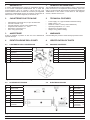
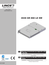
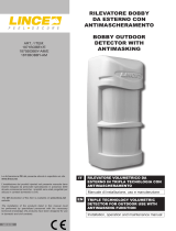
Fig. 1 - Contenuto della Confezione / Package Contents
A
B
D
E
F
C
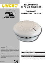
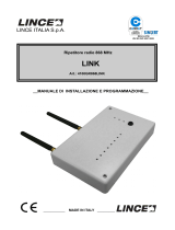
Fig. 2 - Scheda elettronica / Electronic board
AB
C
D
E
F
G
1 GENERALITÀ
Il modulo 1890-MODULO/CI fornisce la possibiltà di disporre
di un modulo contaimpulsi autoalimentato che, in base alla
programmazione, apre un contatto a relè di tipo NC. Può
essere utilizzato insieme ai rilvetori di movimento per tapparelle
410LESW e 1828LESW/E oppure con rilevatori di movimento di
altre marche o con sensori magnetici, di vibrazione, etc...
2 CARATTERISTICHE TECNICHE
• Alimentazione: pila al litio da 3,6 V tipo AA 2600 mAh.
• Corrente nominale: 7 µA.
• Corrente massima: 0,6 mA (2 mA modalità test).
• Temperatura di esercizio: +5 ÷ +40°C.
• Dimensioni: 145x102x16 mm.
• Peso: 160 g (senza pila).
3 AVVERTENZE
Evitare di installare il prodotto in aree che sono direttamente
esposte all’acqua.
4 IDENTIFICAZIONE DELLE PARTI
4.1 CONTENUTO DELLA CONFEZIONE
4.2 SCHEDA ELETTRONICA
Rif. Descrizione
AInvolucro plastico
BCoperchio
CViti (2 pezzi)
DManuale di istruzioni
EPila 3,6V AA (art. 001515/00205AA)
FBiadesivoperssaggio
Rif. Descrizione
ASwitch di test
BLED di test
CMorsettiera uscita
NC
DBuzzer
EDip-Switch
FPila
GCavi di connessione
al contatto
1 GENERAL INFORMATIONS
The 1890-MODULO/CI makes possible to have a self powered
pulse counter that, in accompliance with the settings, open a NC
relay. It can be used with the contacts for shutters 410LESW and
1828LESW/E or with contats of other brans or with magnetic
sensors, vibration sensors, etc...
2 TECHNICAL FEATURES
• Power supply: 3.6 V type AA 2600 mAh lithium battery.
• Rated current: 7 µA.
• Maximum current: 0.6 mA (2 mA modalità test).
• Operating temperature: +5 ÷ +40°C.
• Dimensions: 145x102x16 mm.
• Weight: 160 g (without battery).
3 WARNINGS
Avoid installing the product in areas directly exposed to water.
4 IDENTIFICATION OF PARTS
4.1 PACKAGE CONTENTS
4.2 ELECTRONIC BOARD
Rif. Description
APlastic casing
BCover
CScrews (2 pieces)
DInstruction manual
EAA size 3.6V battery (art. 001515/00205AA)
FDouble-sidedadhesivestripforxing
Rif. Description
ATest switch.
B Test LED.
CNC output
terminal block
DBuzzer
EDip-Switch
FBattery
GCables for
connection to
the contact

3
LINCE ITALIA S.p.A.
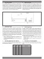
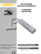
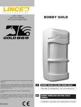
Fig. 3 - Installazione / Installation
5 INSTALLAZIONE
Se si desidera utillizzare il contaimpulsi in abbinamento al
410LESWcollegareilichefuoriesconodalmodulocontaimpulsi
direttamente sulla morsettiera del rilevatore. Nel caso venga
utilizzato insieme a un 1828LESW/E, è necessario collegare
manualmenteilichefuoriesconodalcontaimpulsiconquelliche
fuoriescono dal rilevatore. In caso di utilzzo con altra tipologia
disensore,cablareilifacendoriferimentoalmanualerelativo
al sensore stesso. Il nastro biadesivo può essere utilizzato per
ssareildispositivosecondolenecessitàinstallative.
6 FUNZIONE TEST
La funzione di TEST è utile per vericare il funzionamento e
l’installazione del contatto. Tale funzione permette di attivare
il LED, il buzzer e il relè per 5 attivazioni consecutive (dopo 5
attivazioni consecutive il contatto torna nella modalità operativa
normale, LED e buzzer disattivati e relè attivo). Nella funzione di
test il LED (rif. B,g.2)segnalailriconoscimentodiunimpulso
e il buzzer (rif. D, g. 2) segnala l’attivazione dell’allarme al
raggiungimento del numero programmato di impulsi. Per entrare
in modalità di test, inserire la pila (rif. F, g. 2). Per accedere
alla modalità test nuovamente senza togliere e reinserire la pila
eseguire la seguente procedura:
• Alzare e abbassare completamente la tapparella (se il
contatto non è installato simulare l’azione agendo sulla corda
di collegamento alla tapparella).
• Premere il pulsante (rif. A,g.2)entro45secondidall’azione
precedente.
7 PROGRAMMAZIONE DIP-SWITCH
FareriferimentoallatabellasuccessivapercongurareiDIP1,2
e3(rifE,g.2)inmododavariareilnumerodiimpulsinecessario
per la segnalazione di allarme.
DIP 1 DIP 2 DIP 3 NUMERO IMPULSI/ NUMBER
OF PULSES
OFF OFF OFF 1
ON OFF OFF 2
OFF ON OFF 3
ON ON OFF 4
OFF OFF ON 5
ON OFF ON 6
OFF ON ON 7
ON ON ON 8
Tab. 1 - Programmazione Impulsi / Pulse settings
5 INSTALLATION
If you want to use the pulse counter with the 410LESW, connect
the wires that come out from the detector directly on the
terminal block of the detector. If a 1828LESW/E has been used
as detector, it is necessary to manually connect the wires that
come out from the detector with the wires that come out from the
pulse counter. If has to be used another kind of sensor, connect
the wires referring to its installation manual. The double sided
adhesivestripcanbeusedforxingthedevicedependingonthe
installation requirements.
6 TEST FUNCTION
The TEST function is useful to verify contact operation and
installation. This function allows the LED, buzzer and relay to
be activated for 5 consecutive activations (after 5 consecutive
activations the contact goes back to the normal operating mode,
the LED and buzzer are disabled and the relay is active). In the
test function the LED (ref. B,g.2)indicatestherecognitionof
a pulse and the buzzer (ref. D, g. 2) indicates the activation
of the alarm when the programmed number of pulses has been
reached. To access the test mode, insert the battery (ref. F,g.2).
To access the test mode again without removing and reinserting
the battery, follow the procedure below:
• Fully lift and lower the roller shutter (if the contact is not
installed simulate the action by acting on the shutter
connection rope).
• Press the button (ref. A,g.2) within45seconds fromthe
previous action.
7 DIP-SWITCH PROGRAMMING
RefertothetablebelowtoconguretheDIP1,2and3(ref.E,
Fig. 2) to change the number of pulses required for the alarm
signal.

4
LINCE ITALIA S.p.A.
001530/00850AA
LINCE ITALIA S.p.A
Via Variante di Cancelliera, snc
00072 ARICCIA (Roma)
Tel. +39 06 9301801
Fax +39 06 930180232
[email protected] www.lince.net
Le informazioni riportate in questo manuale sono state compilate
con cura, tuttavia LINCE ITALIA S.p.A. non può essere ritenuta
responsabile per eventuali errori e/o omissioni. LINCE ITALIA
S.p.A. si riserva il diritto di apportare in ogni momento e senza
preavviso, miglioramenti e/o modiche ai prodotti descritti
nel presente manuale. Consultare il sito www.lince.net per le
condizioni di assistenza e garanzia. LINCE ITALIA S.p.A. pone
particolare attenzione al rispetto dell’ambiente. Tutti i prodotti ed i
processi produttivi sono progettati con criteri di eco-compatibilità.
Il presente articolo è stato prodotto in Italia.
The information in this manual has been issued with care, but
LINCE ITALIA S.p.A. will not be responsible for any errors or
omissions. LINCE ITALIA S.p.A. reserves the right to improve
or modify the products described in this manual at any time
and without advance notice. Terms and conditions regarding
assistance and the product warranty can be found at LINCE
ITALIA’s website www.lince.net. LINCE ITALIA S.p.A. makes it a
priority to respect the environment. All products and production
processes are designed to be eco-friendly and sustainable.
This product has been Made in Italy
Il dip-switch 4 serve alla programmazione delle seguenti
modalità:
• DIP4 ON Funzionamento A.
• DIP4 OFF Funzionamento B.
Descrizione delle modalità di funzionamento
• Funzionamento A: al termine dell’allarme (dopo 1 ÷ 8
impulsi) il sistema torna in stato di riposo e la linea si
autoescludenchénonvieneripristinatoilcollegamentodel
contatto per tapparella (se la linea del contatto a tapparella
rimane perennemente aperta l’uscita non commuta più).
• Funzionamento B: l’ingresso viene interrogato dal
microprocessorenchénonvienetrovatoinattivo(ilrelèdi
uscita rimane aperto per tutto il tempo in cui l’ingresso del
contatto a tapparella è aperto).
8 BATTERIA
La batteria è una pila di formato AA al Litio con tensione
nominale di lavoro di 3,6 V. Utilizzando la batteria in dotazione
(con capacità nominale 2600 mAh) la seguente tabella mostra la
durata teorica:
• 4 Attivazioni giornaliere: ~ 10 Anni.
• 6 Attivazioni giornaliere: ~ 8 Anni.
• 8 Attivazioni giornaliere: ~ 6 Anni.
Nota: nel calcolo sono state previste 2 attivazioni della funzionalità
TEST.
La batteria scarica viene segnalata con 5 toni intermittenti
dal buzzer ad ogni attivazione, così da informare l’utente di
procedere al cambio della batteria. Dopo circa 10 giorni dalla
prima segnalazione il contatto di allarme verrà denitivamente
aperto (segnalando allarme in centrale) no alla sostituzione
della batteria.
Dip-switch 4 is used to program the following modes:
• DIP4 ON Operating mode A.
• DIP4 OFF Operating mode B.
Description of the operating modes
• Operating mode A: at the end of the alarm (after 1 ÷ 8
pulses) the system goes back to the rest status and the
line is automatically disabled until the roller shutter contact
is reconnected (if the roller shutter contact line stays
permanently open, the output no longer switches over).
• Operating mode B: the input is interrogated by the
microprocessor until it is found inactive (the output relay
stays open while the input of the roller shutter contact is
open).
8 BATTERY
The battery is an AA size lithium battery with rated operating
voltage of 3.6 V. Using the battery supplied (with rated capacity
2600 mAh) the following table shows the theoretical lifetime:
• 4 Daily activations: ~ 10 Years.
• 6 Daily activations: ~ 8 Years.
• 8 Daily activations: ~ 6 Years.
Note: the calculation has taken into account 2 activations of the
TEST function.
A “low battery” status is indicated with 5 intermittent tones of
the buzzer at each activation, in order to inform the user that it
is time to change the battery. After about 10 days from the last
indication, the alarm contact is permanently opened (indicating
the alarm in the control unit) until the battery is replaced.
-
 1
1
-
 2
2
-
 3
3
-
 4
4


Lince 1890-MODULO/CI Istruzioni per l'uso
- Tipo
- Istruzioni per l'uso
in altre lingue
Documenti correlati
-
 Lince 4052GR868RX8 Istruzioni per l'uso
-
 Lince 4048GR868LESW Istruzioni per l'uso
-
 Lince 9590-GOLD-SMOKE Istruzioni per l'uso
-
 Lince 9587-GOLD-AG Istruzioni per l'uso
-
 Lince 9521-GOLD-TXRX Istruzioni per l'uso
-
 Lince 1875BOBBY-AM/E Istruzioni per l'uso
-
 Lince 4100GR868LINK Istruzioni per l'uso
-
 Lince 9553-GOLD-BOBBY-AM-E Istruzioni per l'uso
-
 Lince 1936-GCONT Istruzioni per l'uso


