
PDR922/522 G
Gasbeheizt
de Installationsplan Gewerbliche Trockner
en Installation plan Commercial dryer
fr Schéma d’implantation Sèche-linge professionnels
ru Монтажный план Профессиональные сушильные машины
it Pianta d'installazione Essiccatoio industriale
es Plano de instalación Secadoras industriales
M.-Nr. 11 727 090

2
de ...................................................................................................................................... 4
en ...................................................................................................................................... 13
fr ........................................................................................................................................ 22
ru ....................................................................................................................................... 31
it ........................................................................................................................................ 35
es ....................................................................................................................................... 44

de - Inhalt
3
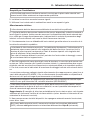
Installationshinweise....................................................................................................... 4
Installationsvoraussetzungen ............................................................................................ 4
Elektroanschluss ............................................................................................................... 4
Gasanschluss.................................................................................................................... 5
Zuluft/Abluft....................................................................................................................... 5
PDR922/522, gasbeheizt................................................................................................ 6
Abmessungen ................................................................................................................... 6
Installation ......................................................................................................................... 7
Aufstellung (Standard/Betonsockel).................................................................................. 8
Technische Daten............................................................................................................ 9
Spannungsvarianten/elektrische Daten............................................................................. 9
Gasanschluss.................................................................................................................... 9
Abluft/Abgas...................................................................................................................... 9
Zuluft ................................................................................................................................. 9
Gerätedaten....................................................................................................................... 10
Befestigungsvarianten....................................................................................................... 10
Befestigung ohne Sockel .............................................................................................. 10
Befestigung auf Betonsockel ........................................................................................ 10
Optionen/Zubehör ............................................................................................................. 11
Betonsockel (bauseitig) ................................................................................................. 11

de - Installationshinweise
4
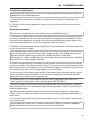
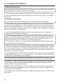
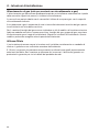
Installationsvoraussetzungen
Der Trockner darf nur vom MieleKundendienst oder einem autorisierten Fachhändler
aufgestellt und in Betrieb genommen werden.
Der Trockner muss in Übereinstimmung mit geltenden Regeln und gültigen Normen in-
stalliert werden.
Betreiben Sie den Trockner immer nur in ausreichend belüfteten und nicht frostgefährde-
ten Räumen.
Elektroanschluss
Der Elektroanschluss muss von einer Elektrofachkraft ausgeführt werden.
Der Elektroanschluss darf nur an eine nach den nationalen Gesetzen, Verordnungen und
Richtlinien sowie den lokalen Bestimmungen und Vorschriften ausgeführte Elektroanlage
erfolgen. Darüber hinaus sind die Vorschriften der Energieversorgungsunternehmen und
Versicherer, die Unfallverhütungsvorschriften sowie die anerkannten Regeln der Technik zu
beachten.
Der zuverlässige und sichere Betrieb des Trockners ist nur dann gewährleistet, wenn
das Gerät am öffentlichen Stromnetz angeschlossen ist.
Die erforderliche elektrische Anschlussspannung, die Leistungsaufnahme und die Vorga-
ben zur Absicherung sind auf dem Typenschild des Trockners angegeben. Vergewissern
Sie sich, dass die Anschlussspannung mit den Spannungswerten auf dem Typenschild
übereinstimmt, bevor der Elektroanschluss ausgeführt wird!
Bei abweichenden Spannungswerten besteht die Gefahr, dass der Trockner durch eine
zu hohe elektrische Anschlussspannung beschädigt wird.
Wenn auf dem Typenschild mehrere Spannungswerte angegeben sind, kann der Trock-
ner für den Anschluss an die jeweilige Eingangsspannung umgeschaltet werden. Diese
Umschaltung darf nur vom MieleKundendienst oder autorisierten Fachhandel durchgeführt
werden. Bei der Umschaltung ist die Umverdrahtungsanweisung auf dem Schaltplan zu
beachten.
Der Trockner kann entweder über einen Festanschluss oder über eine Steckvorrichtung
nach IEC60309-1 angeschlossen werden. Für einen Festanschluss muss am Aufstellungs-
ort eine allpolige Netztrenneinrichtung vorhanden sein.
Als Netztrenneinrichtung gelten Schalter mit einer Kontaktöffnung von mehr als 3mm.
Dazu gehören z.B. Leitungsschutzschalter, Sicherungen und Schütze (IEC/EN60947).
Die Netztrenneinrichtung (einschließlich der Steckvorrichtung) muss gegen unbeabsichtig-
tes und unbefugtes Einschalten gesichert sein, wenn eine permanente Unterbrechung der
Energiezufuhr nicht von jeder Zugangsstelle aus zu überwachen ist.
Tipp: Der Trockner sollte bevorzugt über Steckvorrichtungen angeschlossen werden, damit
elektrische Sicherheitsprüfungen einfacher durchgeführt werden können (z.B. während ei-
ner Wartung oder Instandsetzung).
Es dürfen keine Einrichtungen installiert werden, die den Trockner automatisch aus-
schalten (z.B. Zeitschaltuhren).

de - Installationshinweise
5
Ist es nach lokalen Vorgaben erforderlich einen Fehlerstromschutzschalter (RCD) zu in-
stallieren, muss zwingend ein Fehlerstromschutzschalter TypB (allstromsensitiv) verwen-
det werden.
Gasanschluss
Der Gasanschluss darf nur von einem zugelassenen Installateur unter Einhaltung der län-
derspezifischen Vorschriften vorgenommen werden (siehe Installationsanweisung).
Aufgrund einer zu geringen Durchflussmenge ist die Verwendung einer Gassteckdose bei
der angegebenen Heizleistung nicht zulässig.
Die Gasheizung ist ab Werk entsprechend der gastechnischen Angaben auf dem Aufkleber
an der Geräterückseite eingestellt.
Bei Wechsel der Gasfamilie ist ein Umbausatz beim Kundendienst anzufordern (Maschi-
nentyp, Maschinennummer, sowie die Gasfamilie, Gasgruppe, Gasanschlussdruck und
Aufstellungsland angeben). Beachten Sie die Installationsanweisung. Diese Umstellung
darf nur von einem zugelassenen Fachmann vorgenommen werden.
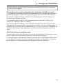
Zuluft/Abluft
Der Trockner darf nur betrieben werden, wenn eine Abluftleitung ordnungsgemäß ange-
schlossen ist und für eine ausreichende Raumbelüftung gesorgt ist.
Zubehörteile dürfen nur dann an- oder eingebaut werden, wenn sie ausdrücklich von
Miele freigegeben sind. Wenn andere Teile an- oder eingebaut werden, gehen Ansprüche
aus Garantie, Gewährleistung und/oder Produkthaftung verloren.

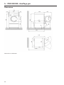
de - PDR922/522, gasbeheizt
6
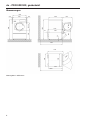
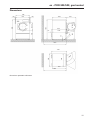
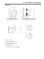
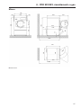
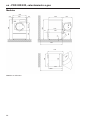
Abmessungen
906
1057
>20
Ø 520
650
1400
900 642
1162
67
1064
1400
20
595 Ø 630
1600
45°
>20
1162
1057
1600
906
900
< 180°
38
Maßangaben in Millimetern

de - PDR922/522, gasbeheizt
7
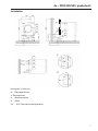
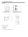
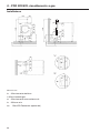
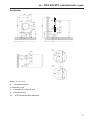
Installation
620 280
90
G
501
305
1600
150
305
1600
~ 50
2 x
150
128
200
EL
AL ZL
ZL
EL
AL
501
G
G
ZL
EL
AL
AL
ZL
161
160
"Z"
"Y"
"Y"
"Z"
XCI
96
31
~350 28
128
Maßangaben in Millimetern
EL Elektroanschluss
GGasanschluss
AL Abluftanschluss
ZL Zuluft
XCI XCI-/Connector-Box (optional)

de - PDR922/522, gasbeheizt
8
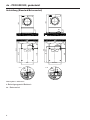
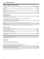
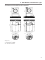
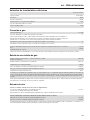
Aufstellung (Standard/Betonsockel)
20
1400
Ø 10
1400
BS
395
B
~ 48
55
1059
~ 55
>50
Ø 10
~ 55
B
1600
55
790
395
1066
900
534
BB
A
A
BS >1200
>55
BS >900
534
1066
B
B
BB
A - A B - B
>55
790
1600
~ 48
BS
>50
20
Maßangaben in Millimetern
BBefestigungspunkt/Bohrloch
BS Betonsockel

de - Technische Daten
9
Spannungsvarianten/elektrische Daten
Standardanschluss
Anschlussspannung 1N AC 230V
Frequenz 50Hz
Leistungsaufnahme 1,0kW
Elektrische Absicherung (bauseitig) 10A
Mindestquerschnitt für Anschlusskabel 3×1,5mm²
Kabelverschraubung M20
Gasanschluss
Heizleistung 21,5kW
Geräteanschluss, maschinenseitig nach ISO7-1
Zum Anschluss des Gasgerätes muss eine gewellte Metallschlauchleitung aus nicht rostendem Stahl nach
DIN 3384 verwendet werden. Die Absperreinrichtung ist bauseits zu stellen. Aufgrund einer zu geringen
Durchflussmenge ist die Verwendung einer Gassteckdose bei der angegebenen Heizleistung nicht zulässig.
½"
Anschlussgewinde für Erdgas, bauseitig (Innengewinde) ½"
Anschlussgewinde für Flüssiggas, bauseitig (Innengewinde) ½"
Alternativer Anschluss für Flüssiggas mit Präzisionsstahlrohr nach DIN2391/2393, mit glattem Rohr endend
Mindestanschlusslänge
DN12
40mm
Anschlussdruck gemäß DINEN437. Der Gasanschluss muss nach den nationalen und lokalen Bestimmungen ausgeführt werden.
Abluft/Abgas
Maximaler Nennvolumenstrom im Abluftbetrieb (nur PDR9xx) 810m³/h
Maximaler Nennvolumenstrom (nur PDR5xx) 810m³/h
Maximal zulässiger Druckverlust 290Pa
Anschlussstutzen, maschinenseitig (Außendurchmesser) 150mm
Anschlussrohr, bauseitig (Innendurchmesser) 150mm
Maximale Abluft-/Abgastemperatur 80°C
Der Trockner ist eine Gasfeuerstätte ohne Strömungssicherung mit Gebläse hinter dem Wärmetauscher (Bauart: B22). Die Abgaslei-
tung muss druckdicht sein. Der Abgasanschluss muss nach den nationalen und lokalen Bestimmungen ausgeführt werden und unter-
liegt, je nach nationalen Vorgaben, einer Genehmigung oder Abnahme.
Da die relative Luftfeuchtigkeit innerhalb der Abluftführung bis zu 100% betragen kann, muss durch geeignete Maßnahmen ausge-
schlossen werden, dass zurückfließendes Kondensat in das Gerät gelangen kann.
Zuluft
Standardanschluss: Zuluft aus dem Aufstellraum
Empfohlener freier Zuluftquerschnitt in den Raum:
(Entspricht dem 3-fachen Abluftquerschnitt eines Gerätes).
531cm²
Dem Aufstellraum muss entsprechend der Abluftmenge Zuluft zugeführt werden.
Alternativanschluss: Zuluftanschluss direkt von außen
Anschlussmuffe, maschinenseitig (Innendurchmesser) 161mm
Anschlussrohr, bauseitig (Außendurchmesser) 160mm
Beim Entfernen des Schutzdeckels werden spannungsführende Teile frei. Aus Sicherheitsgründen muss an der zentralen Frischluftan-
saugung des Trockners (über eine Mindestlänge von 900 mm) ein Rohr installiert und mit 2Schrauben gesichert werden.

de - Technische Daten
10
Gerätedaten
Gerätebreite über alles 906mm
Gerätehöhe über alles 1.400mm
Gerätetiefe über alles 1.162mm
Nischenbreite 1.250mm
Empfohlener Wandabstand (bis Gerätevorderkante) 1.600mm
Mindestwandabstand (bis zur Deckelhinterkante) 500mm
Verpackungsbreite 1.090mm
Verpackungshöhe 1.526mm
Verpackungstiefe 1.254mm
Maximales Bruttovolumen 2.085,8l
Maximales Bruttogewicht 218,4kg
Maximales Nettogewicht 203,9kg
Maximale Bodenbelastung im Betrieb 2.324N
Durchmesser Abluftstutzen 150mm
Trommeldurchmesser 850mm
Trommelöffnungsdurchmesser 520mm
Trommeltiefe 742mm
Trommelvolumen 400l
Türöffnungsdurchmesser 520mm
Maximaler Türöffnungswinkel 180°
Emissions-Schalldruckpegel 62 dB(A) re 20 µPa
Schallleistungspegel 70
Durchschnittliche Wärmeabgabe an den Raum 2,6MJ/h
Zulässiger Umgebungstemperaturbereich 2–40°C
Befestigungsvarianten
Befestigung ohne Sockel
Anzahl Schraubengröße
Spannlaschen 2
Holzschrauben DIN 571 (Ø×Länge) 2 6×40mm
Dübel (Ø×Länge) 2 10×50mm
Eine Gerätebefestigung ist unbedingt erforderlich.
Das Befestigungsmaterial für schwimmenden Estrich muss bauseitig gestellt werden.
Befestigung auf Betonsockel
Anzahl Schraubengröße
Spannlaschen 2
Holzschrauben DIN 571 (Ø×Länge) 2 6×40mm
Dübel (Ø×Länge) 2 10×50mm
Bei der Geräteaufstellung auf einen bauseitigen Betonsockel ist die Gerätebefestigung unbedingt erforderlich.
Das Befestigungsmaterial für schwimmenden Estrich muss bauseitig gestellt werden.

de - Technische Daten
11
Optionen/Zubehör
Betonsockel (bauseitig)
Mindestbreite 900mm
Empfohlene Höhe 100mm
Mindesthöhe 50mm
Mindesttiefe 1.200mm
Die Betongüte und deren Festigkeit müssen entsprechend der Gerätebelastung bemessen werden. Der bauseitige Betonsockel muss
eine ausreichende Bodenhaftung zum Untergrund aufweisen.

enen - Contents
12
Installation notes ............................................................................................................. 13
Installation requirements ................................................................................................... 13
Electrical connection......................................................................................................... 13
Gas connection ................................................................................................................. 14
Air intake/exhaust air......................................................................................................... 14
PDR922/522, gas heated................................................................................................ 15
Dimensions........................................................................................................................ 15
Installation ......................................................................................................................... 16
Installation (standard/on concrete plinth).......................................................................... 17
Technical data.................................................................................................................. 18
Voltage variants/electrical data ......................................................................................... 18
Gas connection ................................................................................................................. 18
Waste air/gas..................................................................................................................... 18
Air intake............................................................................................................................ 18
Machine data..................................................................................................................... 19
Fixing options.................................................................................................................... 19
Fixing without plinth ...................................................................................................... 19
Fixing to concrete plinth................................................................................................ 19
Options/Accessories ......................................................................................................... 20
Concrete base (on site) ................................................................................................. 20

en - Installation notes
13
Installation requirements
The tumble dryer must only be installed and commissioned by Miele Customer Service
Department or an authorised dealer.
The tumble dryer must be installed in accordance with all relevant regulations and
standards.
The dryer must only be operated in a room that has sufficient ventilation and which is
frost-free.
Electrical connection
The electrical connection must be established by a qualified electrician.
The electrical connection may only be made to an electrical system provided in accord-
ance with all appropriate local and national legislation, regulations and guidelines. Please
also observe the regulations set out by your insurance provider and energy supplier, acci-
dent prevention regulations, as well as recognised codes of practice.
Reliable and safe operation of this tumble dryer is only ensured if it has been connected
to the mains electricity supply.
The required supply voltage, power rating and fuse rating can be found on the data plate
on the tumble dryer. Ensure that the supply voltage matches the voltage quoted on the
data plate before establishing the electrical connection to the tumble dryer.
Connection to a supply voltage other than the one quoted on the data plate can damage
the tumble dryer if the voltage is too high.
If more than one voltage is specified on the data plate, the tumble dryer can be conver-
ted for connection to the relevant input voltage. This conversion must be performed by the
Miele Customer Service Department or by an authorised dealer. During the conversion, the
wiring instructions given on the wiring diagram must be followed.
The tumble dryer can either be hard-wired or connected using a plug-and-socket connec-
tion in accordance with IEC60309-1. For a hard-wired connection, an all-pole isolation
device must be available at the installation site.
An isolation device is a switch which ensures a contact opening of more than 3mm.
These include circuit breakers, fuses and contactors (IEC/EN60947).
If the mains supply cannot be permanently disconnected, the isolation device (including
plug and socket) must be safeguarded against being switched on either unintentionally or
without authorisation.
Tip: We recommend connecting the tumble dryer to the power supply via a plug and
socket so that it is easier to conduct electrical safety checks (e.g. during maintenance or
repair work).
The tumble dryer must not be connected to devices such as timers which would switch
it off automatically.
If local regulations require that a residual current device (RCD) is installed, a typeB re-
sidual current device (sensitive to universal current) must be used.

en - Installation notes
14
Gas connection
The gas connection must only be carried out by a registered installation technician in ac-
cordance with the applicable national regulations (see installation instructions).
The use of a gas socket is not permitted at the specified heater rating as the flow rate is
too low.
The gas heating is configured at the factory in line with the gas specifications on the
sticker on the rear of the appliance.
If the gas family is changed, a conversion kit must be requested from the Miele Cus-
tomerService Department (please specify the appliance type, serial number, gas family,
gas group, gas connection pressure and country of installation). Follow the installation in-
structions. This conversion may only be carried out by a registered specialist.
Air intake/exhaust air
The tumble dryer may only be operated when the ducting has been connected properly
and the room is sufficiently ventilated.
Accessory parts may only be fitted when expressly approved by Miele. If other parts are
used, warranty, performance and product liability claims will be invalidated.

en - PDR922/522, gas heated
15
Dimensions
906
1057
>20
Ø 520
650
1400
900 642
1162
67
1064
1400
20
595 Ø 630
1600
45°
>20
1162
1057
1600
906
900
< 180°
38
Dimensions quoted in millimetres

en - PDR922/522, gas heated
16
Installation
620 280
90
G
501
305
1600
150
305
1600
~ 50
2 x
150
128
200
EL
AL ZL
ZL
EL
AL
501
G
G
ZL
EL
AL
AL
ZL
161
160
"Z"
"Y"
"Y"
"Z"
XCI
96
31
~350 28
128
Measurements in millimeters
EL Electrical connection
GGas connection
AL Exhaust duct
ZL Air intake
XCI XCI Box/Connector Box (optional)

en - PDR922/522, gas heated
17
Installation (standard/on concrete plinth)
20
1400
Ø 10
1400
BS
395
B
~ 48
55
1059
~ 55
>50
Ø 10
~ 55
B
1600
55
790
395
1066
900
534
BB
A
A
BS >1200
>55
BS >900
534
1066
B
B
BB
A - A B - B
>55
790
1600
~ 48
BS
>50
20
Dimensions quoted in millimetres
BDrill hole/anchor point
BS Concrete plinth

en - Technical data
18
Voltage variants/electrical data
Standard connection
Supply voltage 1N AC 230V
Frequency 50Hz
Power rating 1.0kW
Fuse rating (on site) 10A
Minimum cross-section for connection cable 3×1.5mm²
Cable gland M20
Gas connection
Nominal heat rating 21,5kW
Machine-side connection according to ISO 7-1
To connect the gas appliance, a corrugated metal hose line made of stainless steel according to DIN3384
must be used. The shut-off device must be provided on-site. Due to an insufficient flow rate, the use of a
gas socket is not permissible with the specified heating output.
½"
Connection thread for natural gas, on-site (internal thread) ½"
Connection thread for liquid gas, on-site (internal thread) ½"
Alternative on-site connection with high-precision steel pipe according to DIN 2391/DIN2393, with smooth
pipe end
Min. connection length
DN12
40mm
Connection pressure according to DIN EN 437. Connection to gas supply must comply with national regulations.
Waste air/gas
Max. nominal air flow in vented mode (PDR9xx only) 810m³/h
Max. nominal air flow (PDR5xx only) 810m³/h
Max. permissible pressure loss 290Pa
Connection on machine side (ext. diameter) 150mm
Connection pipe provided on site (int. diameter) 150mm
Max. temperature 80°C
This tumble dryer is a gas-burning machine without a flow-operated safety device with fan downstream of heat exchanger (technical
design: B22). Waste gas pipework must be pressure-tight. Waste gas connections should be performed in accordance with national
and local regulations and may require approval.
As relative humidity inside the vent ducting can be as high as 100%, suitable measures must be taken to prevent a backflow of con-
densate into the machine.
Air intake
Standard connection: air intake from installation site
Recommended free air intake cross-section into the room:
(equivalent to 3 times the exhaust air cross-section of a machine).
531cm²
There must be sufficient air intake to the installation site to match the air outlet volume.
Alternative connection: air intake connection directly from outdoors
Connection sleeve on machine side (internal diameter) 161mm
Connection pipe provided on site (external diameter) 160mm
Removing the protective cover exposes live parts. For safety reasons, a pipe must be installed from the tumble dryer’s central fresh air
intake (over a minimum length of 900mm) and secured with 2screws.

en - Technical data
19
Machine data
Machine width, total 906mm
Machine height, total 1400mm
Machine depth, total 1162mm
Niche width 1250mm
Recommended wall spacing (up to the front edge of the machine) 1600mm
Minimum wall spacing (up to the back edge of the lid) 500mm
Packaging width 1090mm
Packaging height 1526mm
Packaging depth 1254mm
Maximum gross volume 2085.8l
Maximum gross weight 218.4kg
Maximum net weight 203.9kg
Max. floor load in operation 2.324N
Diameter of exhaust duct 150mm
Drum diameter 850mm
Diameter of drum opening 520mm
Drum depth 742mm
Drum volume 400l
Diameter of door opening 520mm
Maximum door opening angle 180°
Emission sound pressure level 62 dB(A) re 20 µPa
Sound power level 70
Average heat dissipation rate into the room 2.6MJ/h
Permissible ambient temperature range 2–40°C
Fixing options
Fixing without plinth
Quantity Screw size
Tensioning strips 2
Wood screws DIN571 (Ø×length) 2 6×40mm
Plugs (Ø×length) 2 10×50mm
Fixing the appliance in place is absolutely essential.
Fastenings for floating screed must be supplied by the customer on site.
Fixing to concrete plinth
Quantity Screw size
Tensioning strips 2
Wood screws DIN571 (Ø×length) 2 6×40mm
Plugs (Ø×length) 2 10×50mm
If the tumble dryer is being fixed to a concrete plinth on site, fixing in place is absolutely essential.
Fastenings for floating screed must be supplied by the customer on site.

en - Technical data
20
Options/Accessories
Concrete base (on site)
Minimum width 900mm
Recommended height 100mm
Minimum height 50mm
Minimum depth 1200mm
The quality of the concrete and its strength must be assessed according to the machine load. The on-site concrete plinth must be fixed
adequately to the floor.
La pagina si sta caricando...
La pagina si sta caricando...
La pagina si sta caricando...
La pagina si sta caricando...
La pagina si sta caricando...
La pagina si sta caricando...
La pagina si sta caricando...
La pagina si sta caricando...
La pagina si sta caricando...
La pagina si sta caricando...
La pagina si sta caricando...
La pagina si sta caricando...
La pagina si sta caricando...
La pagina si sta caricando...
La pagina si sta caricando...
La pagina si sta caricando...
La pagina si sta caricando...
La pagina si sta caricando...
La pagina si sta caricando...
La pagina si sta caricando...
La pagina si sta caricando...
La pagina si sta caricando...
La pagina si sta caricando...
La pagina si sta caricando...
La pagina si sta caricando...
La pagina si sta caricando...
La pagina si sta caricando...
La pagina si sta caricando...
La pagina si sta caricando...
La pagina si sta caricando...
La pagina si sta caricando...
La pagina si sta caricando...
-
 1
1
-
 2
2
-
 3
3
-
 4
4
-
 5
5
-
 6
6
-
 7
7
-
 8
8
-
 9
9
-
 10
10
-
 11
11
-
 12
12
-
 13
13
-
 14
14
-
 15
15
-
 16
16
-
 17
17
-
 18
18
-
 19
19
-
 20
20
-
 21
21
-
 22
22
-
 23
23
-
 24
24
-
 25
25
-
 26
26
-
 27
27
-
 28
28
-
 29
29
-
 30
30
-
 31
31
-
 32
32
-
 33
33
-
 34
34
-
 35
35
-
 36
36
-
 37
37
-
 38
38
-
 39
39
-
 40
40
-
 41
41
-
 42
42
-
 43
43
-
 44
44
-
 45
45
-
 46
46
-
 47
47
-
 48
48
-
 49
49
-
 50
50
-
 51
51
-
 52
52


in altre lingue
- français: Miele PDR 922 Guide d'installation
- español: Miele PDR 922 Guía de instalación
- Deutsch: Miele PDR 922 Installationsanleitung
Documenti correlati
-
Miele PDR 922/522 EL Commercial Dryer Guida d'installazione
-
Miele PDR 928 G Guida d'installazione
-
Miele PDR 918 Guida d'installazione
-
Miele PDR 914 Installation Plan
-
-
-
-
Miele PDR 944 Manuale utente
-
-