Pioneer DJM-750MK2 Guida Rapida
- Categoria
- Controller DJ
- Tipo
- Guida Rapida

Français Deutsch ItalianoEnglish
DJM-750MK2
РусскийPortuguêsEspañol
Nederlands
pioneerdj.com/support/
rekordbox.com
Operating Instructions (Quick Start Guide)
Mode d’emploi (Guide de démarrage rapide)
Bedienungsanleitung (Kurzanleitung)
Istruzioni per l’uso (Guida di avvio veloce)
DJ MIXER
TABLE DE MIXAGE
DJ-MISCHPULT
MIXER PER DJ
For FAQs and other support information for this product, visit the above site.
Pour les FAQ et autres informations de support sur ce produit, consultez le site ci-dessus.
Häufig gestellte Fragen und weitere Support-Informationen für dieses Produkt finden Sie auf der oben
genannten Seite.
Per la sezione FAQ e altre informazioni di supporto per questo prodotto, visitare il sito indicato sopra.
MESA DE MEZCLAS DJ
MESA DE MISTURA PARA DJ
Bezoek de bovenstaande website voor vaak gestelde vragen en andere informatie over ondersteuning voor dit
product.
Para consultar las preguntas más frecuentes y otras informaciones de asistencia para este producto, visite el
sitio indicado anteriormente.
Para obter informações sobre as FAQs e outras informações de apoio relativas a este produto, consulte o site
indicado acima.
Ответы на часто задаваемые вопросы и другую дополнительную информацию о данном изделии см.
на указанном выше сайте.
Handleiding (Snelstartgids)
Manual de instrucciones (Guía de inicio rápido)
Manual de instruções (Guia de início rápido)
Инструкции по эксплуатации
(Краткое руководство пользователя)
DJ
микшерный
пульт
DJ MENGPANEEL

En
2
CAUTION
TO PREVENT THE RISK OF ELECTRIC SHOCK, DO NOT
REMOVE COVER (OR BACK). NO USER
-SERVICEABLE
PA
RTS INSIDE. REFER SERVICING TO QUALIFIED
SERVICE PERSONNEL.
D3-4-2-1-1_B1_En
WARNING
This equipment is not waterproof
. To prevent a fire or
shock hazard, do not place any container filled with
liquid near this equipment (such as a vase or flower
pot) or expose it to dripping, splashing, rain or
moisture.
D3-4-2-1-3_A1_En
WARNING
This product equipped with a three-wire grounding
(earthed) plug - a plug that has a third (grounding) pi
n.
This plug only fits a grounding-type power outlet. If you
are unable to insert the plug into an outlet, contact a
licensed electrician to replace the outlet with a properly
grounded one. Do not defeat the safety purpose of the
grounding plug.
D3-4-2-1-6_A1_En
WARNING
To
prevent a fire hazard, do not place any naked flame
sources (such as a lighted candle) on the equipment.
D3-4-2-1-7a_A1_En
Operating Envir
onment
Operating environment temperature and humidit
y:
+5 °C to +35 °C (+41 °F to +95 °F); less than 85 %RH
(cooling vents not blocked)
Do not install this unit in a poorly ventilated area, or in
locations exposed to high humidity or direct sunlight (or
strong artificial light).
D3-4-2-1-7c*_A2_En
CAUTION
The switch on this unit will not completely shut off
all power from the AC outlet. Since the power cord
serves as the main disconnect device for the unit,
you will need to unplug it from the AC outlet to shut
down all power. Therefore, make sure the unit has
been installed so that the power cord can be easily
unplugged from the AC outlet in case of an accident.
To avoid fire hazard, the power cord should also be
unplugged from the AC outlet when left unused for a
long period of time (for example, when on vacation).
D3-4-2-2-2a*_A1_En
WARNING
Store small parts out of the reach of children and
infants. If accidentally swallowed, contact a doctor
immediately.
D41-6-4_A1_En
This product is for general household purposes. Any
failure due to use for other than household purposes
(such as long-term use for business purposes in a
restaurant or use in a car or ship) and which requires
repair will be charged for even during the warranty
period.
K041_A1_En
If you want to dispose this product, do not mix it with general household waste. There is a separate collection system for used
electronic products in accordance with legislation that requires proper treatment, recovery and recycling.
P
rivate households in the member states of the EU, in Switzerland and Norway may return their used electronic products free of charge to
designated collection facilities or to a retailer (if you purchase a similar new one).
Fo
r countries not mentioned above, please contact your local authorities for the correct method of disposal.
By doing so you will ensure that your disposed product undergoes the necessar
y treatment, recovery and recycling and thus prevent potential
negative effects on the environment and human health.
K058b_A1_En
When using this product, confirm the safety
information shown on the bottom of the unit.
D3-4-2-2-4_B1_En
VENTILATION CAUTION
When installing this unit, make sure to leave space
around the unit for ventilation to improve heat radiation
(at least 5 cm at rear, and 5 cm at each side).
D3-4-2-1-7d*_A1_En
The graphical symbol placed on the product
means alternating current.
The graphical symbol placed on the product
means direct current.
The graphical symbol placed on the product
means Class II equipment.
D3-8-2-4_A1_En
D3-4-2-1-6b_B1_En
Laite on liitettävä suojamaadoituskoskettimilla
varustettuun pistorasiaan
For Finland customers
For Norway customers
For Sweden customers
Apparatet må tilkoples jordet stikkontakt
For Denmark customers
Apparatets stikprop skal tilsluttes en stikkontakt med
jord, som giver forbindelse til stikproppens jord.
Apparaten skall anslutas till jordat uttag
CAUTION
This product is evaluated in moderate and tropical
climate condition.
D3-8-2-1-7a_A1_En

En
3
POWER-CORD CAUTION
Handle the power cord by the plug. Do not pull out the
plug by tugging the cord and never touch the power
cord when your hands are wet as this could cause a
short circuit or electric shock. Do not place the unit, a
piece of furniture, etc., on the power cord, or pinch the
cord. Never make a knot in the cord or tie it with other
cords. The power cords should be routed such that they
are not likely to be stepped on
. A damaged power cord
can cause a fire or give you an electrical shock. Check
the power cord once in a while. When you find it
damaged, ask your nearest se
rvice center or your
dealer for a replacement.
S002*_A1_En
English

En
4
Contents
How to read this manual
Thank you for purchasing this Pioneer DJ product.
Read this manual and the Operating Instructions that is available on the
Pioneer DJ site before using the product. Both contain important infor-
mation that you should understand to properly use the product.
! In this manual, names of channels and buttons on the product,
menus in the software, etc., are enclosed in square brackets ([ ]).
(e.g. [MASTER] channel, [ON/OFF], [Start]menu)
! Screens, external appearance, and software and hardware specifica-
tions described in this manual are based on the product that is still
under development and may differ from the final specifications.
! Depending on your operating system, the web browser settings,
etc., the procedures described in this manual may differ from actual
operations.
This manual provides brief descriptions of the part names and the con-
nection between the unit and peripherals. For more instructions on how
to use this product, refer to the Operating Instructions for this product.
! For obtaining the Operating Instructions for this product, see
Obtaining the Operating Instructions on page 5 .
Before start
Features ....................................................................................................... 5
Accessories ................................................................................................. 5
Obtaining the Operating Instructions....................................................... 5
Part names and functions
Rear panel ................................................................................................... 6
Control Panel .............................................................................................. 7
Connections
Connecting input terminals ....................................................................... 9
Connecting output terminals .................................................................. 10
Operation
Basic Operation ........................................................................................ 11
Changing the settings .............................................................................. 11
Additional information
Troubleshooting ........................................................................................ 12
Trademarks and registered trademarks ................................................. 12
Cautions on copyrights ............................................................................ 12
Specifications............................................................................................ 13

En
5
English
Before start
Features
This 4-channel DJ mixer is the next model in the DJM series from
Pioneer DJ, the world standard in the disco and club scene. It sup-
ports various types of DJ performances by incorporating the EQ FADER
CURVE, SOUND COLOR FX, BEAT FX, and SEND/RETURN functions for
mixing that were newly developed for the DJM-900NXS2, which is equip-
ment for permanent installation in a club. This mixer provides strong
support for any DJ performance by featuring a high sound quality, highly
reliable design, and panel layout providing high operability, and support-
ing connections to a wide range of devices including a USB sound card
capable of connecting with a PC, Mac, or iOS device.
Accessories
! Power cord
! USB cable
! Operating Instructions (Quick Start Guide) (this document)
! Warranty (for some regions)
1
! License key card (rekordbox dj, rekordbox dvs)
1 The included warranty is for the European region.
Cautions
The license key cannot be reissued. Be careful not to lose it.
Obtaining the Operating
Instructions
For details on rekordbox dj and the driver software, see the Operating
Instructions.
Some operating instructions are provided in PDF files.
Adobe
®
Reader
®
is required to view the PDF files.
1 Launch a web browser on a computer and access the
following Pioneer DJ site.
pioneerdj.com
2 Click [Support].
3 Click [FIND TUTORIALS & MANUALS].
4 Click [DJM-750MK2] in the [Mixer] category.
5 Click on the desired language on the download page.

En
6
Part names and functions
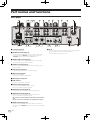
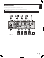
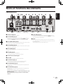
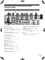
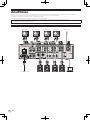
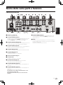
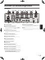
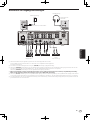
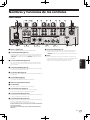
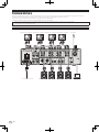
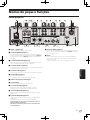
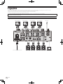
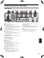
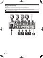
Rear panel
1 4 54 54 54 5 62
ad c
3
7
89
b
1 u button (page 11 )
Turns this unit on and off.
2 RETURN terminals (page 10 )
Connect to output terminals of an external effects unit. If a cable
is connected to the [L (MONO)] terminal only, the input to the
[L (MONO)] terminal is also input to the [R] channel.
3 SIGNAL GND terminal (page 9 )
Connect a ground wire of an analog player to reduce noise that
occurs when an analog player is connected.
4 PHONO terminals (page 9 )
Connect a phono level (MM cartridge) output device. Do not input
line level signals.
5 LINE terminals (page 9 )
Connect a DJ player or a line level output component.
6 MIC terminal (page 9 )
Connects a microphone.
Phantom power supply is not supported.
7 Kensington security slot
8 USB terminal
Connect a computer with a USB cable.
9 BOOTH terminals (page 10 )
These are output terminals for a booth monitor.
Be sure to use these as balanced outputs.
a MASTER2 terminals (page 10 )
Connect to analog input terminals of a power amplifier, etc.
b MASTER1 terminals (page 10 )
Connect to analog input terminals of a power amplifier, etc.
Be sure to use these as balanced outputs.
Be careful not to accidentally insert the power cord of another
unit.
Do not connect the terminal that can supply phantom power.
c SEND terminals (page 10 )
Connect to input terminal of an external effects unit. If a cable is
connected to the [L (MONO)] terminal only, a monaural audio signal
is output.
d AC IN
Connect to a power outlet with a supplied power cord. Connect the
power cord after all the connections are completed.
Be sure to use the supplied power cord.

En
7
English
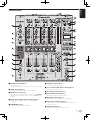
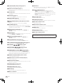
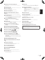
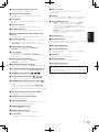
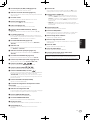
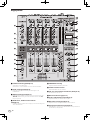
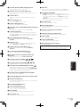
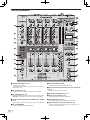
Control Panel
8
3
2
w
7
5
g
u
v
i
c
F
G
H
e
d
f
h
j
k
r
C
E
m
n
o
p
q
s
t
y
z
A
D
1
4
6
a
9
b
g
i
c
e
d
f
h
b
g
i
c
e
d
f
h
b
g g
i
c
e
d
f
h
b
l
B
x
1 PHONES terminal (page 11 )
Connect headphones.
1/4” stereo phone plugs and 3.5 mm stereo mini plugs are supported.
2 LEVEL control (page 11 )
Adjusts the level of sound output from the headphones.
3 MIXING control (page 11 )
Adjusts the monitor volume balance for the sound of the [MASTER]
channel and the sound of the channel for which the [CUE] button is
pressed.
4 MONO SPLIT, STEREO selector switch (page 11 )
Sets the distribution of the monitor sound output from the
headphones.
5 PARAMETER control
Adjusts the SOUND COLOR FX parameter.
6 SOUND COLOR FX buttons
Turns on and off SOUND COLOR FX.
7 OFF, ON, TALK OVER selector switch (page 11 )
Turns the microphone on and off.
8 Microphone indicator (page 11 )
9 EQ (HI, LOW) controls (page 11 )
Adjusts the sound quality of the microphones.
a MIC LEVEL control (page 11 )
Adjusts the level of sound output from the microphone.
b Input selector switches (page 11 )
Selects the input source for each channel from the components
connected to this unit.
c TRIM control (page 11 )
Adjusts the level of sound input to each channel.

En
8
d EQ/ISO (HI, MID, LOW) controls (page 11 )
Adjusts the sound quality of each channel.
e Channel Level Indicator (page 11 )
Displays the sound level of each channel before it passes through
the channel faders.
f COLOR control
This changes the parameters of the SOUND COLOR FX of the differ-
ent channels.
g CUE button (page 11 )
Presses the [CUE] button of the channel to be monitored.
h Channel Fader (page 11 )
Adjusts the level of sound output from each channel.
i CROSS FADER ASSIGN (A, THRU, B) selector switch
(page 11 )
Sets the output destination of each channel to [A] or [B].
j Crossfader (page 11 )
Outputs audio signals assigned by the crossfader assign switch cor-
responding to the curve characteristics selected by [CROSS FADER]
(Crossfader Curve Selector Switch).
k MASTER LEVEL control (page 11 )
Adjusts the level of sound are output from the [MASTER1] and
[MASTER2] terminals.
l CLIP indicators
Master: Flashes when audio with an excessive volume level is output
from the [MASTER1] or [MASTER2] terminals.
m Master Level Indicator (page 11 )
Displays the level of sound output from the [MASTER1] and
[MASTER2] terminals.
n BOOTH MONITOR control (page 11 )
Adjusts the level of sound output from the [BOOTH] terminal.
o EQ CURVE (ISOLATOR, EQ) selector switch (page 11 )
Sets the function of the [EQ/ISO (HI, MID, LOW)] controls.
p CH FADER ( , , ) selector switch
Sets the curve characteristics of the channel fader.
q CROSS FADER ( , , ) selector switch
Sets the curve characteristics of the crossfader.
r SEND/RETURN (1/4” JACK, ) selector switch
Sets the input and output sources for the SEND/RETURN channel.
You can select the device connected to the [SEND/RETURN] ter-
minals on the rear panel of this unit or the device connected to the
mobile device connection terminal on the operation panel.
s RETURN TYPE (AUX, INSERT) selector switch
Sets the SEND/RETURN method.
t Mobile device connection terminal (USB port)
Connect a mobile device.
u USB connection indicator
Lights when a mobile device is connected. Blinks when an incompat-
ible device is connected.
v SEND/RETURN ON/OFF button
Turns SEND/RETURN on and off.
w SEND/RETURN LEVEL control
Adjusts the sound level of SEND/RETURN.
x Main display
Displays the effect name, BPM, effect parameter, etc.
y BEAT c, d buttons
Sets the beat fraction for synchronizing the effect sound.
z TAP button
When the BPM measurement mode is set to [TAP], tap this button
with a finger to input the BPM manually.
A UTILITY (WAKE UP) button
— UTILITY: Press and hold down this button to display the
[UTILITY] screen. It lights when the [UTILITY] screen is dis-
played. Press this button when the [UTILITY] screen is displayed
to return to the normal screen.
— WAKE UP: Lights when the product enters standby mode. Press
this button in standby mode to exit standby mode.
B AUTO/TAP button
Sets the BPM measurement mode.
C FX FREQUENCY button
Sets the range to apply BEAT FX. BEAT FX is applied to the lit button.
D Beat effect selector switch
Sets the BEAT FX type.
E Effect channel selector switch
Sets the channel to apply the BEAT FX and SEND/RETURN to.
F TIME control
Adjusts the BEAT FX time parameter.
G LEVEL/DEPTH control
Adjusts the BEAT FX quantitative parameter.
H Beat effect ON/OFF button
Turns BEAT FX on and off.
Do not pull on the channel fader and crossfader knobs with excessive
force. The knobs have a structure by which they cannot be pulled off
easily. Pulling the knobs strongly may result in damaging the unit.

En
9
English
Connections
Turn off this unit and disconnect the power cord from the power outlet before connecting components or changing the connections.
Connect the power cord to a power outlet after all the connections are completed.
Be sure to use the power cord supplied with this unit.
Refer to the operating instructions for the components to be connected.
! When connecting this unit with a computer, be sure to use the USB cable supplied with this unit.
! A USB hub cannot be used.
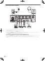
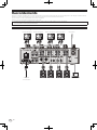
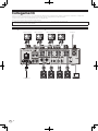
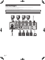
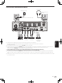
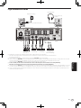
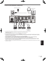
Connecting input terminals
L
R
L
R
L
R
L
R
L
R
L
R
L
R
Computer
Pioneer DJ’s DJ playerPioneer DJ’s DJ playerTo power outlet
rekordbox
L
R
Analog player Analog player Analog player Analog player
Microphone

En
10
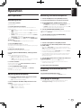
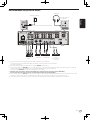
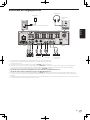
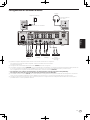
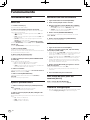
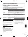
Connecting output terminals
L
R
Power amplifier
3
Power amplifier
3
Power amplifier
(for booth monitor)
5
External effector
2
4
Mobile device
1
Rear panel
Top panel of unit
USB port covers
USB hubs cannot be used.
Headphones
6
1 When connecting a mobile device, use the cable supplied with the device.
For information on compatible mobile devices, see the Pioneer DJ site below.
pioneerdj.com/support/
2 Also connect the external effector to the [RETURN] terminal (input terminal).
3 Be sure to use the [MASTER1] terminals for a balanced output. If it is connected to an unbalanced input (such as RCA) with an XLR to RCA con-
verter cable (or converter adapter), etc., the sound quality may be lowered or noise may occur.
Use the [MASTER2] terminals for an unbalanced input (such as RCA).
4 Be careful not to accidentally insert the power cord of another unit to [MASTER1] terminal.
Do not connect the terminal that can supply phantom power to the [MASTER1] terminal.
5 Be sure to use the [BOOTH] terminals for a balanced output. If they are connected to an unbalanced input (such as an RCA or TS input) with an
TRS to RCA converter cable (or converter adapter), TS cable, etc., the sound quality may be lowered or noise may occur.
6 Connect headphones to either the phone jack or the mini jack. If both jacks are used at the same time, the sound quality and volume may be
lowered.

En
11
English
Operation
Basic Operation
Outputting sound
1 Press the [u] button.
This unit turns on.
2 Set the input selector switches.
Select an input source for each channel from the components con-
nected to this unit.
! [ ]: Selects the computer connected to the [USB] terminal as
an input source.
! [LINE]: Selects the device connected to the [LINE] terminals as
an input source.
! [PHONO]: Selects the analog player connected to the [PHONO]
terminals as an input source.
! [RETURN AUX]: Selects the [SEND/RETURN] [RETURN] sound.
When using [RETURN AUX], selects [AUX] using the [SEND/RETURN]
[RETURN TYPE].
When using [SEND/RETURN], see the Operating Instructions.
3 Turn the [TRIM] control.
Adjusts the level of sound input to each channel.
The channel level indicator lights when audio signals are properly input
to the channel.
4 Move the channel fader up.
Adjusts the level of sound output from each channel.
5 Set the [CROSS FADER ASSIGN (A, THRU, B)] selector
switch.
Set the output destination of each channel.
— [A]: Outputs to [A] (left) of the crossfader.
— [B]: Outputs to [B] (right) of the crossfader.
— [THRU]: Selects this when you do not want to use the crossfader.
(The signals do not pass through the crossfader.)
6 Set the crossfader.
Skip this operation when the [CROSS FADER ASSIGN (A, THRU, B)]
selector switch is set to [THRU].
7 Turn the [MASTER LEVEL] control.
Audio signals are output from the [MASTER1] and [MASTER2]
terminals.
The master level indicator lights.
Adjusting the sound quality
1 Set the [EQ CURVE (ISOLATOR, EQ)] selector switch.
— [ISOLATOR]: Adjusts the isolator settings.
— [EQ]: Adjusts the equalizer settings.
2 Turn the [EQ/ISO (HI, MID, LOW)] controls for each
channel.
The adjustable ranges for each control are as follows.
— [HI]: –26 dB to +6 dB (20 kHz)
— [MID]: –26 dB to +6 dB (1 kHz)
— [LOW]: –26 dB to +6 dB (20 Hz)
Monitoring sound with headphones
1 Connect headphones to the [PHONES] terminal.
2 Press the [CUE] button for the channel to monitor.
3 Set the [MONO SPLIT, STEREO] selector switch.
— [MONO SPLIT]: Outputs the sound of the channel selected with
the [CUE] button to [L] and the sound of MASTER to R.
— [STEREO]: Outputs the sound of the channel for which the [CUE]
button is pressed in stereo from the headphones.
4 Turn the [HEADPHONES MIXING] control.
Adjust the balance of the volume between the channel selected with the
[CUE] button and MASTER.
5 Turn the [LEVEL] control for [HEADPHONES].
Adjust the volume of the headphones.
Using a microphone
1 Connect a microphone to the [MIC] terminal.
2 Set the [OFF, ON, TALK OVER] selector switch to [ON]
or [TALK OVER].
! When set to [TALK OVER], the sound of channels other than the
[MIC] channel is attenuated by 18 dB (default) if a sound of –10 dB or
greater is input to the microphone.
! The sound attenuation level of [TALK OVER] can be set in [UTILITY].
For details, see the Operating Instructions.
! The TALK OVER mode has a normal mode and an advanced mode
(default), and those modes can be switched. For details, see the
Operating Instructions.
3 Turn the [MIC LEVEL] control to adjust the audio level
of the microphone.
Adjust the level of sound output from the [MIC] channel.
! Note that the sound is output at a loud volume if the control is
rotated to the extreme right.
4 Input audio to the microphone.
Outputting sound from the [BOOTH]
terminals
Turn the [BOOTH MONITOR] control.
Adjusts the level of sound output from the [BOOTH] terminal.
Changing the settings
! For details on how to change the settings of this unit, refer to
“Changing the settings” in the Operating Instructions.

En
12
Additional information
Troubleshooting
! If something is wrong with this unit, check the following issues, and also access the Pioneer DJ site and check [FAQ] for [DJM-750MK2].
pioneerdj.com/support/
Sometimes the problem may lie in another component. Inspect the other components and electrical appliances being used. If the problem cannot
be rectified, ask your nearest service center or your dealer to carry out repair work.
! This unit may not operate properly due to static electricity or other external influences. In such cases, disconnect the power cord and connect it
again to restore normal operation.
Problem Check Remedy
Sound is not output, or sound is too
small.
Is the input selector switch set to the proper
position?
Change the input source for the channel using the input selector switch.
(page 11 )
Are the connection cables properly connected? Connect the connection cables properly. (page 9 )
Are the terminals and plugs dirty? Clean the terminals and plugs before connecting them to the unit.
Is [MASTER ATT.] set to [- 6 dB], etc.? Switch [MASTER ATT.] in the [UTILITY] screen.
Sound is distorted. Is the level of sound output from the [MASTER]
channel appropriately set?
Adjust the [MASTER LEVEL] control so that the master channel level indicator
lights around [0 dB] at the peak level. (page 11 )
Is the level of audio input to each channel properly
set?
Adjust the [TRIM] control so that the channel level indicator lights at about
[0 dB] at the peak level. (page 11 )
The crossfade function does not work. Are the [CROSS FADER ASSIGN (A, THRU, B)]
selector switches properly set?
Set the [CROSS FADER ASSIGN (A, THRU, B)] selector switches for the different
channels properly. (page 11 )
Sound is distorted when an analog
player is connected to the [PHONO]
terminals.
Or, lighting of the channel level
indicator does not change when the
[TRIM] control is turned.
Is an analog player with a built-in phono equalizer
connected to this unit?
Connect the analog player with built-in phono equalizer to the [LINE] terminals.
(page 9 )
Set the PHONO/LINE selector switch on the analog player to PHONO if available.
Is an audio interface for computers connected
between the analog player and this unit?
If the output of the audio interface for computers is line level, connect it to the
[LINE] terminals. (page 9 )
Set the PHONO/LINE selector switch on the analog player to PHONO if available.
Trademarks and registered
trademarks
! "Pioneer DJ" is a trademark of PIONEER CORPORATION, and is used
under license.
! rekordbox is a trademark or registered trademark of the Pioneer DJ
Corporation.
The names of companies and products mentioned herein are trade-
marks or registered trademarks of their respective owners.
Cautions on copyrights
rekordbox restricts playback and duplication of copyright-protected
music contents.
! When coded data, etc., for protecting the copyright is embedded in
the music contents, it may not be possible to operate the program
normally.
! When rekordbox detects that coded data, etc., for protecting the
copyright is embedded in the music contents, processing (playback,
reading, etc.) may stop.
Recordings you have made are for your personal enjoyment and accord-
ing to copyright laws may not be used without the consent of the copy-
right holder.
! Music recorded from CDs, etc., is protected by the copyright laws of
individual countries and by international treaties. It is the full respon-
sibility of the person who has recorded the music to ensure that it is
used legally.
! When handling music downloaded from the Internet, etc., it is the
full responsibility of the person who has downloaded the music to
ensure that it is used in accordance with the contract concluded
with the download site.

En
13
English
Specifications
General – Main Unit
Power requirements ....................................AC 110 V to 240 V, 50 Hz/60 Hz
Power consumption ............................................................................... 40 W
Power consumption (standby) ............................................................. 0.3 W
Main unit weight ...................................................................................6.6 kg
Max. external dimensions ...
320 mm (W) × 107.9 mm (H) × 387.9 mm (D)
Tolerable operating temperature ........................................+5 °C to +35 °C
Tolerable operating humidity ...................... 5 % to 85 % (no condensation)
Audio Section
Sampling rate .......................................................................................48 kHz
Frequency characteristic
LINE ................................................................................. 20 Hz to 20 kHz
S/N ratio (rated output)
PHONO............................................................................................ 87 dB
LINE ............................................................................................... 105 dB
MIC .................................................................................................. 79 dB
Total harmonic distortion (LINE — MASTER1) ................................0.005 %
Standard input level / Input impedance
PHONO.............................................................................–52 dBu/47 kW
LINE ..................................................................................–12 dBu/47 kW
MIC ..................................................................................... –57 dBu/3 kW
RETURN ............................................................................–12 dBu/47 kW
Standard output level / Load impedance / Output impedance
MASTER1 .............................................................. + 6 dBu/10 kW/300 W
MASTER2 .............................................................. + 2 dBu/10 kW/680 W
BOOTH .................................................................. + 6 dBu/10 kW/300 W
SEND (when RETURN TYPE is "AUX") ..................–6 dBu/10 kW/680 W
SEND (when RETURN TYPE is "INSERT") ............–12 dBu/10 kW/680 W
PHONES ........................................................+ 8 dBu/32 W/10 W or less
Rated output level / Load impedance
MASTER1 ........................................................................ +25 dBu/10 kW
MASTER2 ........................................................................ +21 dBu/10 kW
Crosstalk (LINE) .................................................................................... 82 dB
Channel equalizer characteristic
HI .....................................................................–26 dB to +6 dB (20 kHz)
MID .................................................................... –26 dB to +6 dB (1 kHz)
LOW ..................................................................–26 dB to +6 dB (20 Hz)
Microphone equalizer characteristic
HI ...................................................................–12 dB to +12 dB (10 kHz)
LOW ..............................................................–12 dB to +12 dB (100 Hz)
Input / Output terminals
PHONO input terminal
RCA pin jacks ..................................................................................4 sets
LINE input terminal
RCA pin jacks ..................................................................................4 sets
MIC input terminal (XLR/TRS)
XLR connector & 1/4” TRS jack ........................................................1 set
RETURN Input terminals (TS)
1/4” TS jack ........................................................................................ 1 set
MASTER output terminal
XLR connector...................................................................................1 set
RCA pin jacks ....................................................................................1 set
BOOTH output terminal
1/4” TRS jack .....................................................................................1 set
SEND output terminal (TS)
1/4” TS jack ........................................................................................ 1 set
PHONES output terminal
1/4” stereo phone jack ...................................................................... 1 set
3.5 mm stereo mini jack ...................................................................1 set
USB terminal
Type A ................................................................................................1 set
Power supply...5 V/2.1 A or less
B type ................................................................................................. 1 set
! The specifications and design of this product are subject to change
without notice.
! © 2017 Pioneer DJ Corporation. All rights reserved.

Fr
2
ATTENTION
POUR ÉVITER TOUT RISQUE D’ÉLECTROCUTION, NE PAS
ENLEVER LE COUVERCLE (NI LE PANNEAU ARRIÈRE).
AUCUNE PIÈCE RÉPARABLE PAR L’UTILISATEUR NE SE
TROUVE À L’INTÉRIEUR. CONFIER TOUT ENTRETIEN À
UN PERSONNEL QUALIFIÉ UNIQUEMENT.
D3-4-2-1-1_B1_Fr
AVERTISSEMENT
Cet appareil n’est pas étanche. Pour éviter les risques
d’incendie et de décharge électrique, ne placez près de lui
un récipient rempli d’eau, tel qu’un vase ou un pot de
fleurs, et ne l’exposez pas à des gouttes d’eau, des
éclaboussures, de la pluie ou de l’humidité.
D3-4-2-1-3_A1_Fr
AVERTISSEMENT
Cet appareil est muni d’une fiche de mise à la terre (masse) à
trois fils. Comme la fiche présente une troisième broche (de
terre), elle ne peut se brancher que sur une prise de courant,
prévue pour une mise à la terre. Si vous n’arrivez pas à insérer
la fiche dans la prise de courant, contactez un électricien
qualifié pour faire remplacer la prise par une qui soit mise à la
terre. N’annulez pas la fonction de sécurité que procure cette
fiche de mise à la terre.
D3-4-2-1-6_A1_Fr
AVERTISSEMENT
Pour éviter les risques d’incendie, ne placez aucune
flamme nue (telle qu’une bougie allumée) sur
l’appareil. D3-4-2-1-7a_A1_Fr
Milieu de fonctionnement
Température et humidité du milieu de fonctionnement :
De +5 °C à +35 °C (de +41 °F à +95 °F) ; Humidité
relative inférieure à 85 % (orifices de ventilation non
obstrués)
N’installez pas l’appareil dans un endroit mal ventilé ou
un lieu soumis à une forte humidité ou en plein soleil
(ou à une forte lumière artificielle). D3-4-2-1-7c*_A1_Fr
ATTENTION
L’interrupteur de cet appareil ne coupe pas
complètement celui-ci de sa prise secteur. Comme le
cordon d’alimentation fait office de dispositif de
déconnexion du secteur, il devra être débranché au
niveau de la prise secteur pour que l’appareil soit
complètement hors tension. Par conséquent, veillez à
installer l’appareil de telle manière que son cordon
d’alimentation puisse être facilement débranché de
la prise secteur en cas d’accident. Pour éviter tout
risque d’incendie, le cordon d’alimentation sera
débranché au niveau de la prise secteur si vous
prévoyez une période prolongée de non utilisation
(par exemple avant un départ en vacances).
D3-4-2-2-2a*_A1_Fr
AVERTISSEMENT
Gardez les pièces de petite taille hors de la portée des bébés
et des enfants. En cas d’ingestion accidentelle, veuillez
contacter immédiatement un médecin.
D41-6-4_A1_Fr
Ce produit est destiné à une utilisation domestique
générale. Toute panne due à une utilisation autre qu'à
des fins privées (comme une utilisation à des fins
commerciales dans un restaurant, dans un autocar
ou sur un bateau) et qui nécessite une réparation
sera aux frais du client, même pendant la période de
garantie. K041_A1_Fr
Si vous souhaitez vous débarrasser de cet appareil, ne le mettez pas à la poubelle avec vos ordures ménagères. Il existe un système de
collecte séparé pour les appareils électroniques usagés, qui doivent être récupérés, traités et recyclés conformément à la législation.
Les habitants des états membres de l’UE, de Suisse et de Norvège peuvent retourner gratuitement leurs appareils électroniques usagés aux
centres de collecte agréés ou à un détaillant (si vous rachetez un appareil similaire neuf).
Dans les pays qui ne sont pas mentionnés ci-dessus, veuillez contacter les autorités locales pour savoir comment vous pouvez vous débarrasser
de vos appareils.
Vous garantirez ainsi que les appareils dont vous vous débarrassez sont correctement récupérés, traités et recyclés et préviendrez de cette façon
les impacts néfastes possibles sur l’environnement et la santé humaine.
K058b_A1_Fr
NOTE IMPORTANTE SUR LE CABLE
D’ALIMENTATION
Tenir le câble d’alimentation par la fiche. Ne pas
débrancher la prise en tirant sur le câble et ne pas
toucher le câble avec les mains mouillées. Cela risque
de provoquer un court-circuit ou un choc électrique. Ne
pas poser l’appareil ou un meuble sur le câble. Ne pas
pincer le câble. Ne pas faire de noeud avec le câble ou
l’attacher à d’autres câbles. Les câbles d’alimentation
doivent être posés de façon à ne pas être écrasés. Un
câble abîmé peut provoquer un risque d’incendie ou un
choc électrique. Vérifier le câble d’alimentation de
temps en temps. Contacter le service après-vente le
plus proche ou le revendeur pour un remplacement.
S002*_A1_Fr
Lorsque vous utilisez ce produit, vérifiez les
informations concernant la sécurité sous l’appareil.
D3-4-2-2-4_B1_Fr
PRÉCAUTION DE VENTILATION
Lors de l’installation de l’appareil, veillez à laisser un
espace suffisant autour de ses parois de manière à
améliorer la dissipation de chaleur (au moins 5 cm à
l’arrière et 5 cm de chaque côté).
D3-4-2-1-7d*_A1_Fr
Le symbole graphique indiqué sur le produit
représente le courant alternatif.
Le symbole graphique indiqué sur le produit
représente le courant continu.
Le symbole graphique indiqué sur le produit
représente un équipement de Classe II.
D3-8-2-4_A1_Fr
ATTENTION
Ce produit a été testé dans des conditions de climats
tempéré et tropical. D3-8-2-1-7a_A1_Fr

Fr
3
Sommaire
Comment lire ce manuel
Merci d’avoir acheté ce produit Pioneer DJ.
Lisez ce manuel et le mode d’emploi disponible sur le site de Pioneer DJ
avant d’utiliser le produit. Ces deux documents contiennent des infor-
mations importantes que vous devez comprendre pour utiliser correcte-
ment le produit.
En particulier, veillez à lire les “CONSIGNES DE SÉCURITÉ
IMPORTANTES”. En outre, veillez à conserver ce manuel avec la
“Garantie”.
! Dans ce manuel, les noms de canaux et de touches sur le produit,
les menus dans le logiciel, etc., sont indiqués entre crochets ([ ]).
(Par exemple : canal [MASTER], [ON/OFF], menu [Démarrer])
! Les écrans, l’aspect externe et les spécifications du matériel et du
logiciel décrits dans ce manuel sont basés sur le produit qui est
encore en cours de développement et peuvent être différents des
spécifications définitives.
! Selon votre système d’exploitation, des paramètres du navigateur
Web, etc., les procédures décrites dans ce manuel peuvent être
différentes des opérations réelles.
Ce manuel décrit brièvement les noms des éléments et le raccordement
entre l’appareil et des périphériques. Pour plus d’instructions sur l’utili-
sation de ce produit, reportez-vous au mode d’emploi de ce produit.
! Pour obtenir le mode d’emploi de ce produit, reportez-vous à la
page 4 , Obtention du mode d’emploi.
Informations préliminaires
Caractéristiques .......................................................................................... 4
Accessoires ................................................................................................. 4
Obtention du mode d’emploi ..................................................................... 4
Noms et fonctions des éléments
Panneau arrière .......................................................................................... 5
Panneau de commande ............................................................................. 6
Raccordements
Raccordement des prises d’entrée ........................................................... 8
Raccordement des prises de sortie .......................................................... 9
Fonctionnement
Opérations de base ................................................................................... 10
Changement des réglages ....................................................................... 10
Informations supplémentaires
En cas de panne ....................................................................................... 11
Marques commerciales et marques déposées ..................................... 11
Précautions concernant les droits d’auteur .......................................... 11
Spécifications............................................................................................ 12
Français

Fr
4
Informations préliminaires
Caractéristiques
Cette table de mixage à 4 canaux est le nouveau modèle de la série
DJM de Pioneer DJ, la référence mondiale pour les discothèques et les
clubs. Elle permet différents types de prestations DJ grâce aux fonctions
de mixage EQ FADER CURVE, SOUND COLOR FX, BEAT FX et SEND/
RETURN nouvellement développées pour la DJM-900NXS2, un équi-
pement installé en permanence dans une discothèque. Cette table de
mixage s’adapte à tous les types de prestations DJ en offrant une haute
qualité sonore, une conception extrêmement fiable et une disposition du
panneau de commande facilitant les manipulations, et en permettant le
raccordement à un grand nombre d’appareils, y compris une carte son
USB compatible avec un PC, un Mac ou un appareil iOS.
Accessoires
! Cordon d’alimentation
! Câble USB
! Mode d’emploi (Guide de démarrage rapide) (le présent document)
! Garantie (pour certaines régions)
1
! Carte de clé de licence (rekordbox dj, rekordbox dvs)
1 La garantie incluse est destinée à la région européenne.
Attention
La clé de licence ne peut pas être redélivrée. Veillez à ne pas la perdre.
Obtention du mode d’emploi
Pour plus d’informations sur rekordbox dj et sur le pilote, reportez-vous
au mode d’emploi.
Certains modes d’emploi sont fournis sous forme de fichiers PDF.
Adobe
®
Reader
®
est nécessaire pour visualiser les fichiers PDF.
1 Lancez un navigateur Web sur un ordinateur et
accédez au site de Pioneer DJ suivant.
pioneerdj.com
2 Cliquez sur [Support].
3 Cliquez sur [FIND TUTORIALS & MANUALS].
4 Cliquez sur [DJM-750MK2] dans la catégorie [Mixer].
5 Cliquez sur la langue souhaitée sur la page de
téléchargement.

Fr
5
Français
Noms et fonctions des éléments
Panneau arrière
1 4 54 54 54 5 62
ad c
3
7
89
b
1 Touche u (page 10 )
Pour allumer et éteindre cet appareil.
2 Prises RETURN (page 9 )
Raccordez aux prises de sortie d’un générateur d’effets externe. Si
un câble est raccordé uniquement à la prise [L (MONO)], l’entrée
vers la prise [L (MONO)] est également transmise au canal [R].
3 Prise SIGNAL GND (page 8 )
Raccordez le fil de terre d’un lecteur analogique pour réduire le bruit
produit lorsqu’un lecteur analogique est raccordé.
4 Prises PHONO (page 8 )
Raccordez un dispositif à sortie phono (cellule MM). N’entrez pas de
signaux de niveau de ligne.
5 Prises LINE (page 8 )
Raccordez un lecteur DJ ou un composant de sortie de niveau de
ligne.
6 Prise MIC (page 8 )
Permet de raccorder un microphone.
L’alimentation fantôme n’est pas prise en charge.
7 Fente de sécurité Kensington
8 Prise USB
Raccordez un ordinateur à l’aide d’un câble USB.
9 Prises BOOTH (page 9 )
Ce sont des prises de sortie pour la surveillance en cabine.
Elles doivent être utilisées comme sorties équilibrées.
a Prises MASTER2 (page 9 )
Raccordez aux prises d’entrées analogiques d’un amplificateur de
puissance, etc.
b Prises MASTER1 (page 9 )
Raccordez aux prises d’entrées analogiques d’un amplificateur de
puissance, etc.
Elles doivent être utilisées comme sorties équilibrées.
Attention de ne pas insérer le cordon d’alimentation d’un autre
appareil par erreur.
Ne raccordez pas la prise qui peut fournir une alimentation
fantôme.
c Prises SEND (page 9 )
Raccordez à la prise d’entrée d’un générateur d’effets externe. Si
un câble est raccordé uniquement à la prise [L (MONO)], un signal
audio monophonique est transmis.
d AC IN
Raccordez à une prise électrique à l’aide du cordon d’alimentation
fourni. Branchez le cordon d’alimentation lorsque tous les raccorde-
ments sont terminés.
Veillez à utiliser le cordon d’alimentation fourni.

Fr
6
Panneau de commande
8
3
2
w
7
5
g
u
v
i
c
F
G
H
e
d
f
h
j
k
r
C
E
m
n
o
p
q
s
t
y
z
A
D
1
4
6
a
9
b
g
i
c
e
d
f
h
b
g
i
c
e
d
f
h
b
g g
i
c
e
d
f
h
b
l
B
x
1 Prise PHONES (page 10 )
Raccordez un casque.
Les jacks stéréo de 1/4” et les mini-jacks stéréo de 3,5 mm.
2 Commande LEVEL (page 10 )
Ajuste le niveau du son provenant du casque d’écoute.
3 Commande MIXING (page 10 )
Ajuste la balance du volume de contrôle du son du canal [MASTER]
et du son du canal dont la touche [CUE] est pressée.
4 Sélecteur MONO SPLIT, STEREO (page 10 )
Définit la répartition du son de contrôle provenant du casque.
5 Commande PARAMETER
Ajuste le paramètre SOUND COLOR FX.
6 Touches SOUND COLOR FX
Activent et désactivent SOUND COLOR FX.
7 Sélecteur OFF, ON, TALK OVER (page 10 )
Active et désactive le microphone.
8 Indicateur du microphone (page 10 )
9 Commandes EQ (HI, LOW) (page 10 )
Ajustent la qualité du son des microphones.
a Commande MIC LEVEL (page 10 )
Ajuster le niveau du son provenant du microphone.
b Sélecteurs d’entrée (page 10 )
Sélectionnent la source d’entrée de chaque canal parmi les compo-
sants raccordés à cet appareil.
c Commande TRIM (page 10 )
Ajuste le niveau du son transmis à chaque canal.
d Commandes EQ/ISO (HI, MID, LOW) (page 10 )
Ajustent la qualité du son de chaque canal.

Fr
7
Français
e Indicateur de niveau de canal (page 10 )
Affiche le niveau du son de chaque canal avant qu’il passe par le
fader de canal.
f Commande COLOR
Change les paramètres de SOUND COLOR FX des différents canaux.
g Touche CUE (page 10 )
Appuie sur la touche [CUE] du canal à contrôler.
h Fader de canal (page 10 )
Ajuste le niveau du son provenant de chaque canal.
i Sélecteur CROSS FADER ASSIGN (A, THRU, B)
(page 10 )
Règle la destination du signal de chaque canal sur [A] ou [B].
j Crossfader (page 10 )
Restitue les signaux audio affectés par le commutateur d’affectation
de crossfader correspondant aux caractéristiques de la courbe sélec-
tionnée par [CROSS FADER] (Sélecteur de courbe de crossfader).
k Commande MASTER LEVEL (page 10 )
Ajuste le niveau du son provenant des prises [MASTER1] et
[MASTER2].
l Indicateurs CLIP
Principal : Clignote lorsqu’un son avec un niveau sonore excessif est
émis par les prises [MASTER1] ou [MASTER2].
m Indicateur de niveau principal (page 10 )
Affiche le niveau du son provenant des prises [MASTER1] et
[MASTER2].
n Commande BOOTH MONITOR (page 10 )
Ajuste le niveau du son provenant de la prise [BOOTH].
o Sélecteur EQ CURVE (ISOLATOR, EQ) (page 10 )
Définit la fonction des commandes [EQ/ISO (HI, MID, LOW)].
p Sélecteur CH FADER ( , , )
Définit les caractéristiques de la courbe du fader de canal.
q Sélecteur CROSS FADER ( , , )
Définit les caractéristiques de la courbe du crossfader.
r Sélecteur SEND/RETURN (1/4” JACK, )
Définit les sources d’entrée et de sortie du canal SEND/RETURN.
Vous pouvez sélectionner le dispositif raccordé aux prises
[SEND/RETURN] sur le panneau arrière de cet appareil ou le dispo-
sitif raccordé à la prise de raccordement du dispositif portable sur le
panneau de commande.
s Sélecteur RETURN TYPE (AUX, INSERT)
Définit la méthode SEND/RETURN.
t Prise de raccordement du dispositif portable (port
USB)
Raccordez un dispositif portable.
u Indicateur de liaison USB
S’allume lorsqu’un dispositif portable est connecté. Clignote
lorsqu’un dispositif incompatible est connecté.
v Touche SEND/RETURN ON/OFF
Active et désactive SEND/RETURN.
w Commande SEND/RETURN LEVEL
Ajuste le niveau sonore de SEND/RETURN.
x Écran principal
Affiche le nom de l’effet, le BPM, le paramétrage d’effet, etc.
y Touches BEAT c, d
Spécifient la fraction de temps utilisée pour synchroniser le son
auquel l’effet est appliqué.
z Touche TAP
Lorsque le mode de mesure du BPM est réglé sur [TAP], tapez sur
cette touche avec un doigt pour définir manuellement le BPM.
A Touche UTILITY (WAKE UP)
— UTILITY : Maintenez cette touche enfoncée pour afficher l’écran
[UTILITY]. Elle s’allume lorsque l’écran [UTILITY] est affiché.
Appuyez sur cette touche lorsque l’écran [UTILITY] s’affiche pour
revenir à l’écran normal.
— WAKE UP : S’allume lorsque le produit passe en mode de veille.
Appuyez sur cette touche en mode de veille pour quitter le mode
de veille.
B Touche AUTO/TAP
Définit le mode de mesure du BPM.
C Touche FX FREQUENCY
Définit la plage à laquelle appliquer BEAT FX. BEAT FX est appliqué à
la touche allumée.
D Sélecteur d’effet calé sur le tempo
Définit le type BEAT FX.
E Sélecteur de canal d’effet
Définit le canal auquel appliquer BEAT FX et SEND/RETURN.
F Commande TIME
Ajuste le paramètre temporel de BEAT FX.
G Commande LEVEL/DEPTH
Ajuste le paramètre quantitatif de BEAT FX.
H Touche ON/OFF de l’effet calé sur le tempo
Active et désactive BEAT FX.
N’exercez pas de force excessive lorsque vous tirez les boutons de
fader de canal et de crossfader. Les boutons ont une structure qui ne
permet pas de les détacher facilement. L’appareil peut être endom-
magé par une force excessive.

Fr
8
Raccordements
Éteignez cet appareil et débranchez le cordon d’alimentation de la prise électrique avant de raccorder des appareils ou de changer les branchements.
Branchez le cordon d’alimentation à une prise électrique lorsque tous les raccordements sont terminés.
Veillez à utiliser le cordon d’alimentation fourni avec cet appareil.
Reportez-vous au mode d’emploi des appareils à raccorder.
! Lorsque vous raccordez cet appareil à un ordinateur, veillez à utiliser le câble USB fourni avec cet appareil.
! Un concentrateur USB ne peut pas être utilisé.
Raccordement des prises d’entrée
L
R
L
R
L
R
L
R
L
R
L
R
L
R
Lecteur DJ de Pioneer DJLecteur DJ de Pioneer DJÀ une prise
d’ alimentation
Ordinateur
rekordbox
L
R
Lecteur analogique Lecteur analogique Lecteur analogique Lecteur analogique
Microphone
La pagina sta caricando ...
La pagina sta caricando ...
La pagina sta caricando ...
La pagina sta caricando ...
La pagina sta caricando ...
La pagina sta caricando ...
La pagina sta caricando ...
La pagina sta caricando ...
La pagina sta caricando ...
La pagina sta caricando ...
La pagina sta caricando ...
La pagina sta caricando ...
La pagina sta caricando ...
La pagina sta caricando ...
La pagina sta caricando ...
La pagina sta caricando ...
La pagina sta caricando ...
La pagina sta caricando ...
La pagina sta caricando ...
La pagina sta caricando ...
La pagina sta caricando ...
La pagina sta caricando ...
La pagina sta caricando ...
La pagina sta caricando ...
La pagina sta caricando ...
La pagina sta caricando ...
La pagina sta caricando ...
La pagina sta caricando ...
La pagina sta caricando ...
La pagina sta caricando ...
La pagina sta caricando ...
La pagina sta caricando ...
La pagina sta caricando ...
La pagina sta caricando ...
La pagina sta caricando ...
La pagina sta caricando ...
La pagina sta caricando ...
La pagina sta caricando ...
La pagina sta caricando ...
La pagina sta caricando ...
La pagina sta caricando ...
La pagina sta caricando ...
La pagina sta caricando ...
La pagina sta caricando ...
La pagina sta caricando ...
La pagina sta caricando ...
La pagina sta caricando ...
La pagina sta caricando ...
La pagina sta caricando ...
La pagina sta caricando ...
La pagina sta caricando ...
La pagina sta caricando ...
La pagina sta caricando ...
La pagina sta caricando ...
La pagina sta caricando ...
La pagina sta caricando ...
La pagina sta caricando ...
La pagina sta caricando ...
La pagina sta caricando ...
La pagina sta caricando ...
La pagina sta caricando ...
La pagina sta caricando ...
La pagina sta caricando ...
La pagina sta caricando ...
La pagina sta caricando ...
La pagina sta caricando ...
La pagina sta caricando ...
La pagina sta caricando ...
La pagina sta caricando ...
La pagina sta caricando ...
La pagina sta caricando ...
La pagina sta caricando ...
La pagina sta caricando ...
La pagina sta caricando ...
La pagina sta caricando ...
La pagina sta caricando ...
La pagina sta caricando ...
La pagina sta caricando ...
La pagina sta caricando ...
La pagina sta caricando ...
-
 1
1
-
 2
2
-
 3
3
-
 4
4
-
 5
5
-
 6
6
-
 7
7
-
 8
8
-
 9
9
-
 10
10
-
 11
11
-
 12
12
-
 13
13
-
 14
14
-
 15
15
-
 16
16
-
 17
17
-
 18
18
-
 19
19
-
 20
20
-
 21
21
-
 22
22
-
 23
23
-
 24
24
-
 25
25
-
 26
26
-
 27
27
-
 28
28
-
 29
29
-
 30
30
-
 31
31
-
 32
32
-
 33
33
-
 34
34
-
 35
35
-
 36
36
-
 37
37
-
 38
38
-
 39
39
-
 40
40
-
 41
41
-
 42
42
-
 43
43
-
 44
44
-
 45
45
-
 46
46
-
 47
47
-
 48
48
-
 49
49
-
 50
50
-
 51
51
-
 52
52
-
 53
53
-
 54
54
-
 55
55
-
 56
56
-
 57
57
-
 58
58
-
 59
59
-
 60
60
-
 61
61
-
 62
62
-
 63
63
-
 64
64
-
 65
65
-
 66
66
-
 67
67
-
 68
68
-
 69
69
-
 70
70
-
 71
71
-
 72
72
-
 73
73
-
 74
74
-
 75
75
-
 76
76
-
 77
77
-
 78
78
-
 79
79
-
 80
80
-
 81
81
-
 82
82
-
 83
83
-
 84
84
-
 85
85
-
 86
86
-
 87
87
-
 88
88
-
 89
89
-
 90
90
-
 91
91
-
 92
92
-
 93
93
-
 94
94
-
 95
95
-
 96
96
-
 97
97
-
 98
98
-
 99
99
-
 100
100


Pioneer DJM-750MK2 Guida Rapida
- Categoria
- Controller DJ
- Tipo
- Guida Rapida
in altre lingue
- English: Pioneer DJM-750MK2 Quick start guide
- français: Pioneer DJM-750MK2 Guide de démarrage rapide
- español: Pioneer DJM-750MK2 Guía de inicio rápido
- Deutsch: Pioneer DJM-750MK2 Schnellstartanleitung
- русский: Pioneer DJM-750MK2 Инструкция по началу работы
- Nederlands: Pioneer DJM-750MK2 Snelstartgids
- português: Pioneer DJM-750MK2 Guia rápido
Documenti correlati
-
Pioneer DJ Equipment DJM-2000 Manuale utente
-
Pioneer DJM-450 Guida Rapida
-
-
Pioneer DJM-S5 Guida Rapida
-
Pioneer XDJ-RX3 Guida Rapida
-
-
Pioneer DJM-250MK2 Manuale utente
-
Pioneer DJM-S11 Guida Rapida
-
Pioneer DJM-700-K Manuale del proprietario
-
Pioneer XDJ-RX2-W Guida Rapida