
Level 1 and 2 Service Manual
E365
Dual Band Wireless Telephone
E365
GSM 900/1800MHz


6809461A68 June 12, 2003 3
Level 1 and 2 Service Manual Table of Contents
Contents
Introduction . . . . . . . . . . . . . . . . . . . . . . . . . . . . . . . . . . . . . . . . . . . . . . . . . . . . . . . . . . . . . . . . . . . . . . . . . . . . . . 3
Product Identification . . . . . . . . . . . . . . . . . . . . . . . . . . . . . . . . . . . . . . . . . . . . . . . . . . . . . . . . . . . . . . . . 3
Product Names . . . . . . . . . . . . . . . . . . . . . . . . . . . . . . . . . . . . . . . . . . . . . . . . . . . . . . . . . . . . . . . . . . . . . 3
Regulatory Agency Compliance . . . . . . . . . . . . . . . . . . . . . . . . . . . . . . . . . . . . . . . . . . . . . . . . . . . . . . . . 3
Computer Program Copyrights . . . . . . . . . . . . . . . . . . . . . . . . . . . . . . . . . . . . . . . . . . . . . . . . . . . . . . . . 4
About this Service Manual . . . . . . . . . . . . . . . . . . . . . . . . . . . . . . . . . . . . . . . . . . . . . . . . . . . . . . . . . . . . 4
Warranty Service Policy . . . . . . . . . . . . . . . . . . . . . . . . . . . . . . . . . . . . . . . . . . . . . . . . . . . . . . . . . . . . . . 5
Parts Replacement . . . . . . . . . . . . . . . . . . . . . . . . . . . . . . . . . . . . . . . . . . . . . . . . . . . . . . . . . . . . . . . . . . 6
Specifications . . . . . . . . . . . . . . . . . . . . . . . . . . . . . . . . . . . . . . . . . . . . . . . . . . . . . . . . . . . . . . . . . . . . . . . . . . . 7
Product Overview . . . . . . . . . . . . . . . . . . . . . . . . . . . . . . . . . . . . . . . . . . . . . . . . . . . . . . . . . . . . . . . . . . . . . . . . . 9
Features . . . . . . . . . . . . . . . . . . . . . . . . . . . . . . . . . . . . . . . . . . . . . . . . . . . . . . . . . . . . . . . . . . . . . . . . . . . 9
General Operation . . . . . . . . . . . . . . . . . . . . . . . . . . . . . . . . . . . . . . . . . . . . . . . . . . . . . . . . . . . . . . . . . . . . . . . . 12
Controls, Indicators, and Input / Output (I/O) Connectors . . . . . . . . . . . . . . . . . . . . . . . . . . . . . . . . . 12
User Interface Menu Structure . . . . . . . . . . . . . . . . . . . . . . . . . . . . . . . . . . . . . . . . . . . . . . . . . . . . . . . 14
Alert Settings . . . . . . . . . . . . . . . . . . . . . . . . . . . . . . . . . . . . . . . . . . . . . . . . . . . . . . . . . . . . . . . . . . . . . 14
Battery Function . . . . . . . . . . . . . . . . . . . . . . . . . . . . . . . . . . . . . . . . . . . . . . . . . . . . . . . . . . . . . . . . . . . 15
Operation . . . . . . . . . . . . . . . . . . . . . . . . . . . . . . . . . . . . . . . . . . . . . . . . . . . . . . . . . . . . . . . . . . . . . . . . . 15
Tools and Test Equipment . . . . . . . . . . . . . . . . . . . . . . . . . . . . . . . . . . . . . . . . . . . . . . . . . . . . . . . . . . . . . . . . . 17
Disassembly . . . . . . . . . . . . . . . . . . . . . . . . . . . . . . . . . . . . . . . . . . . . . . . . . . . . . . . . . . . . . . . . . . . . . . . . . . . . . 18
Removing and Replacing the Battery Cover and Battery . . . . . . . . . . . . . . . . . . . . . . . . . . . . . . . . . . 18
Removing and Replacing the Subscriber Identity Module (SIM) . . . . . . . . . . . . . . . . . . . . . . . . . . . . . 20
Removing and Replacing the Front Housing . . . . . . . . . . . . . . . . . . . . . . . . . . . . . . . . . . . . . . . . . . . . . 21
Removing and Replacing the Vibrator Motor . . . . . . . . . . . . . . . . . . . . . . . . . . . . . . . . . . . . . . . . . . . . 22
Removing and Replacing the Keypad . . . . . . . . . . . . . . . . . . . . . . . . . . . . . . . . . . . . . . . . . . . . . . . . . . 23
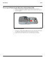
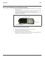
Removing the Antenna/Speaker/Camera Assembly . . . . . . . . . . . . . . . . . . . . . . . . . . . . . . . . . . . . . . . 24
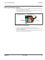
Removing and Replacing the LCD Display Bracket . . . . . . . . . . . . . . . . . . . . . . . . . . . . . . . . . . . . . . . 26
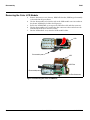
Removing the Earpiece Speaker . . . . . . . . . . . . . . . . . . . . . . . . . . . . . . . . . . . . . . . . . . . . . . . . . . . . . . 27
Removing the Color LCD Module . . . . . . . . . . . . . . . . . . . . . . . . . . . . . . . . . . . . . . . . . . . . . . . . . . . . . 28
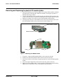
Removing and Replacing the plastic LCD module holder . . . . . . . . . . . . . . . . . . . . . . . . . . . . . . . . . . 29
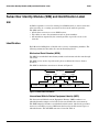
Subscriber Identity Module (SIM) and Identification Label . . . . . . . . . . . . . . . . . . . . . . . . . . . . . . . . . . . . . . . 30
SIM . . . . . . . . . . . . . . . . . . . . . . . . . . . . . . . . . . . . . . . . . . . . . . . . . . . . . . . . . . . . . . . . . . . . . . . . . . . . . 30
Identification . . . . . . . . . . . . . . . . . . . . . . . . . . . . . . . . . . . . . . . . . . . . . . . . . . . . . . . . . . . . . . . . . . . . . . 30
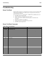
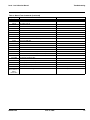
Troubleshooting . . . . . . . . . . . . . . . . . . . . . . . . . . . . . . . . . . . . . . . . . . . . . . . . . . . . . . . . . . . . . . . . . . . . . . . . . 32
Manual Test Mode . . . . . . . . . . . . . . . . . . . . . . . . . . . . . . . . . . . . . . . . . . . . . . . . . . . . . . . . . . . . . . . . . 32
Manual Test Mode Commands . . . . . . . . . . . . . . . . . . . . . . . . . . . . . . . . . . . . . . . . . . . . . . . . . . . . . . . . 32
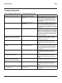
Troubleshooting Chart . . . . . . . . . . . . . . . . . . . . . . . . . . . . . . . . . . . . . . . . . . . . . . . . . . . . . . . . . . . . . . 34
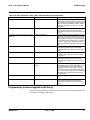
Programming: Software Upgrade and Flexing . . . . . . . . . . . . . . . . . . . . . . . . . . . . . . . . . . . . . . . . . . . 35
Part Number Charts . . . . . . . . . . . . . . . . . . . . . . . . . . . . . . . . . . . . . . . . . . . . . . . . . . . . . . . . . . . . . . . . . . . . . . . 36
Related Publications . . . . . . . . . . . . . . . . . . . . . . . . . . . . . . . . . . . . . . . . . . . . . . . . . . . . . . . . . . . . . . . . 36
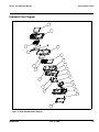
Exploded View Diagram . . . . . . . . . . . . . . . . . . . . . . . . . . . . . . . . . . . . . . . . . . . . . . . . . . . . . . . . . . . . . 37
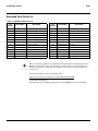
Exploded View Parts List . . . . . . . . . . . . . . . . . . . . . . . . . . . . . . . . . . . . . . . . . . . . . . . . . . . . . . . . . . . 38
Model-Specific Part Numbers . . . . . . . . . . . . . . . . . . . . . . . . . . . . . . . . . . . . . . . . . . . . . . . . . . . . . . . . . 39
Accessories . . . . . . . . . . . . . . . . . . . . . . . . . . . . . . . . . . . . . . . . . . . . . . . . . . . . . . . . . . . . . . . . . . . . . . . . 40
Index . . . . . . . . . . . . . . . . . . . . . . . . . . . . . . . . . . . . . . . . . . . . . . . . . . . . . . . . . . . . . . . . . . . . . . . . . . . . . . . Index-1
E365
6809461A68
Table of Contents

4 June 12, 2003
Table of Contents E365

6809461A68 June 12, 2003 5
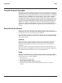
Level 1 and 2 Service Manual Introduction
Introduction
Motorola
®
Inc. maintains a worldwide organization that is dedicated to provide
responsive, full-service customer support. Motorola products are serviced by an
international network of company-operated product care centers as well as
authorized independent service firms.
Available on a contract basis, Motorola Inc. offers comprehensive maintenance and
installation programs which enable customers to meet requirements for reliable,
continuous communications.
To learn more about the wide range of Motorola service programs, contact your local
Motorola products representative or the nearest Customer Service Manager.
Product Identification
Motorola products are identified by the model number on the housing. Use the entire
model number when inquiring about the product. Numbers are also assigned to
chassis and kits. Use these numbers when requesting information or ordering
replacement parts.
Product Names
Product names included in Product Family 0C85 (E365) telephones are listed on
the front cover. Product names are subject to change without notice. Some product
names, as well as some frequency bands, are available only in certain markets.
Regulatory Agency Compliance
This device complies with Part 15 of the FCC Rules. Operation is subject to the
following conditions:
1. This device may not cause any harmful interference, and
2. must accept interference received, including interference that may cause
undesired operation.
This class B device also complies with all requirements of the Canadian
Interference-Causing Equipment Regulations (ICES-003).
Cet appareil numérique de la classe B respecte toutes les exigences du Règlement
sur le matériel brouilleur du Canada.
E365
6809461A68

6 June 12, 2003 6809461A68
Introduction E365
Computer Program Copyrights
The Motorola products described in this manual may include Motorola computer
programs stored in semiconductor memories or other media that are copyrighted
with all rights reserved worldwide to Motorola. Laws in the United States and other
countries preserve for Motorola, Inc. certain exclusive rights to the copyrighted
computer programs, including the exclusive right to copy, reproduce, modify,
decompile, disassemble, and reverse-engineer the Motorola computer programs in
any manner or form without Motorola's prior written consent. Furthermore, the
purchase of Motorola products shall not be deemed to grant either directly or by
implication, estoppel, or otherwise, any license or rights under the copyrights,
patents, or patent applications of Motorola, except for a nonexclusive license to use
the Motorola product and the Motorola computer programs with the Motorola
product.
About this Service Manual
Using this service manual and the suggestions contained in it assures proper
installation, operation, and maintenance of E365 telephones. Refer questions about
this manual to the nearest Customer Service Manager.
A product family is the group of products having the same Account Product Code
(APC). To locate the APC on a device, refer to “Mechanical Serial Number (MSN)”
later in this manual.
Audience
This manual aids service personnel in testing and repairing E365 telephones.
Service personnel should be familiar with electronic assembly, testing, and
troubleshooting methods, and with the operation and use of associated test
equipment.
Use of this manual assures proper installation, operation, and maintenance of
Motorola products and equipment. It contains all service information required for
the equipment described and is current as of the printing date.
Scope
The scope of this document is to provide the basic information relating to E365
telephones, and also to provide procedures and processes for repairing the units at
Level 1 and 2 service centers including:
•Unit swap out
• Repairing of mechanical faults
• Basic modular troubleshooting
• Testing and verification of unit functionality
• Initiate warranty claims and send faulty modules to Level 3 or 4 repair
centers
E365
6809461A68
1 and 2

6809461A68 June 12, 2003 7
Level 1 and 2 Service Manual Introduction
Conventions
Special characters and typefaces, are used in this manual to emphasize certain
types of information.
Warranty Service Policy
The product comes with the standard 12 months warranty terms and conditions.
Accidental damage, misuse, and extended warranties offered by retailers are not
supported under warranty. Non warranty repairs are available at agreed fixed
repair prices.
Out of Box Failure Policy
The standard out of box failure criteria applies. Customer units that fail very early
on after the date of sale, are to be returned to Manufacturing for root cause analysis,
to guard against epidemic criteria. Manufacturing will bear the costs of early life
failure.
Product Support
Customer’s original units will be repaired but not refurbished as standard.
Appointed Motorola Service Hubs will perform warranty and non-warranty field
service for level 2 (assemblies) and level 3 (limited PCB component). The Motorola
High Tech Centers will perform level 4 (full component) repairs.
Customer Support
Customer support is available through dedicated Call Centers and in-country help
desks. Product Service training should be arranged through the local Motorola
Support Center.
➧
Note: Emphasizes additional information pertinent to the subject
matter.
G
Caution: Emphasizes information about actions that may result in
equipment damage.
E
Warning: Emphasizes information about actions that may result in
personal injury.
M
Keys to be pressed are represented graphically. For example, instead of “Press
the Menu Key”, you will see “Press M”.
Information from a screen is shown in text as similar as possible to what
appears in the display. For example, ALERTS or ALERTS.
Information that you need to type is printed in boldface type

8 June 12, 2003 6809461A68
Introduction E365
Parts Replacement
When ordering replacement parts or equipment, include the Motorola part number
and description used in the service manual or supplement.
When ordering crystals or channel elements, specify the Motorola part number,
description, crystal frequency, and operating frequency desired.
When the Motorola part number of a component is not known, use the product model
number or other related major assembly along with a description of the related
major assembly and of the component in question.
In the U.S.A., to contact Motorola, Inc. on your TTY, call: 800-793-7834
Accessories and Aftermarket Division (AAD)
Replacement parts, test equipment, and manuals can be ordered from AAD.
For EMEA spare parts call +44 131 479 1274.
For Asia spare parts call +65 648 62995.
U.S.A. Outside U.S.A.
Phone: 800-422-4210 Phone: 847-538-8023
FAX: 800-622-6210 FAX: 847-576-3023

6809461A68 June 12, 2003 9
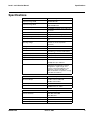
Level 1 and 2 Service Manual Specifications
Specifications
General Function Specification
Frequency Range GSM
880-915 MHz Tx (with EGSM)
925-960 MHZ Rx
Frequency Range DCS
1710-1785 MHz Tx
1805-1880 MHz Rx
Channel Spacing 200 kHz
Channels
174 EGSM, 374 DCS carriers with 8 ch.
per carrier
Modulation GMSK at BT = 0.3
Transmitter Phase Accuracy 5 Degrees RMS, 20 Degrees peak
Duplex Spacing 45 MHz GSM, 95 MHz DCS
Frequency Stability
± 0.10 ppm of the downlink frequency
(Rx)
Operating Voltage
+3.0V dc to +5.1V dc (battery)
+4.4V dc to +6.5V dc (external
connector)
Average Transmit Current 300 mA max
Average Stand-by Current 7 mA max
Dimensions
107 mm x 45 mm x 19.5 mm
(4.2 inches x 1.7 inches x 0.76 inches)
Size (Volume) 80 cc (4.8 in
3
)
Weight 93 gm (2.9 oz)
Temperature Range -10° C to +55° C (+15° F to +130° F)
Battery Life, 740 mAh Li Ion Battery Talk time up to 640 minutes
Standby time up to 150 hours
All talk and standby times are
approximate and depend on network
configuration, signal strength, and
features selected. Standby times are
quoted as a range from DRX=2 to
DRX=9. Talk times are quoted as a range
from DTX off to DTX on.
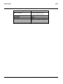
Transmitter Function Specification
RF Power Output
32 dBm nominal GSM 900
29 dBm nominal GSM 1800
30 dBm nominal DCS
Output Impedance 50 ohms nominal
Spurious Emissions
-36 dBm from 0.1 to 1 GHz,
-30 dBm from 1 to 4 GHz
Receiver Function Specification
Receive Sensitivity
-107 dBm GSM 900,
-106 dBm GSM 1800,
-105 dBm DCS
RX bit error rate (100k bits) Type II < 2%
Channel Hop Time 500 microseconds
Time to Camp Approximately 5-10 seconds

10 June 12, 2003 6809461A68
Specifications E365
Speech Coding Function Specification
Speech Coding Type
Regular pulse excitation / linear
predictive coding with long term
prediction (RPE LPC with LTP)
Bit Rate 13.0 kbps
Frame Duration 20 ms
Block Length 260 bits
Classes
Class 1 bits = 182 bits; Class 2 bits = 78
bits
Bit Rate with FEC Encoding 22.8 kbps

6809461A68 June 12, 2003 11
Level 1 and 2 Service Manual Product Overview
Product Overview
Motorola E365 mobile telephones feature global system for mobile communications
(GSM) air interface, general packet radio service (GPRS) transport technology, and
wireless application protocol (WAP) Internet browser. The mobile telephone uses a
simplified icon and graphical-based user interface (UI) for easier operation, allows
short message service (SMS) text messaging, and include clock, alarm, datebook,
calculator, and caller profiling personal management tools. The E365 is a dual band
phone that allows roaming within the GSM 900 MHz and digital cellular system
(DCS) 1800 MHz bands.
E365 telephones support GPRS and SMS in addition to traditional circuit switched
transport technologies. GPRS, where available, provides substantial increases in
mobile data communications performance and the efficient use of radio spectrum.
Data transmission rates for GSM networks can potentially increase from the
current rate of 9.6 kbps up to a theoretical maximum of 171.2 kbps. An increased
data rate is by no means the only benefit provided by GPRS. A key advantage is
the provision of a permanent virtual connection to the network. This “always on”
connection is possible because GPRS uses packet data transfer so that, for example,
email can be downloaded in “background mode.” There is no need for the user to re-
connect before requesting a service, eliminating connection set-up delays and
adding convenience and immediacy to data services access. The “virtual” nature of
this connection means that network resources are not consumed during periods
when a user is not actually sending or receiving data.
The telephones are made of polycarbonate plastic with a metal enclosure. The
display and speaker, as well as the 16-key keypad, transceiver printed circuit board
(PCB), microphone, charger and headphone connectors, and power button are
contained within the candy bar form-factor housing. The user-replaceable 740 mAh
Lithium Ion (LiIon) battery provides up to 640 minutes of talk time with up to 150
hours of standby time
1
. The phone accepts 3V mini subscriber identity module (SIM)
cards which fit into the SIM holder next to the battery. These telephones feature a
128 x 160 pixel high-resolution color graphics display and an internal antenna.
Features
E365 telephones use advanced, self-contained, sealed, custom integrated circuits to
perform the complex functions required for GSM GPRS communication. Aside from
the space and weight advantage, microcircuits enhance basic reliability, simplify
maintenance, and provide a wide variety of operational functions.
Features available in this family of telephones include:
• Lower voltage technology that provides increased standby and talk times
• Extended GSM (EGSM) channels
• Tri-coder/decoder (CODEC) that allows full rate, half rate, and enhanced full
rate modes of transmission
• Supports SMS, concatenated SMS, MMS, QICQ and cell broadcast messages
2
• Supports GPRS, circuit switched, and SMS networks
2
• WAP 2.0 compliant
2
1. All talk and standby times are approximate and depend on network configuration, signal strength, and features selected. Standby
times are quoted as a range from DRX=2 to DRX=9. Talk times are quoted as a range from DTX off to DTX on.
2. Network, subscription and SIM card or service provider dependent feature. Not available in all areas.

12 June 12, 2003 6809461A68
Product Overview E365
• 128 X 160 pixel 65K color graphical display with 4 lines of text, 1 line of icons,
and 1 line of prompts
• Embedded VGA Camera
• Display animation
• VibraCall® vibrating alert
• 4-Way navigation key
• Downloadable wallpaper, icons, animations and MIDI ring tones
3
• Polyphonic speaker supporting 128 different instruments
• Menu Shortcuts, Voice activation for phone book entries
• Simplified text entry using iTAP™ predictive text entry
• Caller line identification (CLI)
3
• Supports call diverting for incoming voice calls
3
• Supports 3V SIM cards
•SIM Toolkit™ Class 2 (STK)
3
• Personal management tools calculator with currency converter, real time clock
with date, reminders, and caller profiling
• Phase II Unstructured Supplementary Service Data (USSD)
3
• Hearing Aid Telephone Interconnection System (HATIS) support
• Chat messaging via WAP over GPRS
3
• Multiple destination SMS
• TrueSync™ Multi-Point Synchronization Capability
Speaker Dependant Voice Activation
The voice dialing feature allows the user to recall pre-programmed voice numbers
simply by pressing the Voice/Ok key and speaking the desired voice tag. Up to 10
voice tags can be stored.
Wireless Access Protocol (WAP) 1.1 Compliancy
In the WAP environment, access to the Internet is initiated in wireless markup
language (WML), which is derived from hypertext markup language (HTML). The
request is passed to a WAP gateway which retrieves the information from the server
in standard HTML (subsequently filtered to WML) or directly in WML if available.
The information is then passed to the mobile subscriber via the mobile network.
The E365’s microbrowser can be configured for baud, idle timeout, line type, phone
number, and connection type.
3. Network, subscription and SIM card or service provider dependent feature. Not available in all areas.
➧
The user cannot place or receive calls while adding voice tags to the phone’s memory.
➧
Because the GSM standard does not provide the option to store voice tags onto the
SIM card, voice tags are added to the phone’s memory.
➧
Bitmap image data will download as text. If the image is larger than the screen,
only part of the image will display.

6809461A68 June 12, 2003 13
Level 1 and 2 Service Manual Product Overview
Simplified Text Entry
iTAP™ predictive text entry. Press a key to generate a character and a dynamic
dictionary uses this to build and display a set of word or name options. The iTAP™
feature may not be available on the phone in all languages.
Caller Line Identification
Upon receipt of a call, the calling party’s phone number is compared to the phone
book. If the number matches a phone book entry, that name will be displayed. If
there is no phone book entry, the incoming phone number will be displayed. In the
event that no caller identification information is available, an incoming call message
is displayed.
SIM Toolkit™ - Class 2
SIM Application Toolkit is a value-added service delivery mechanism that allows
GSM operators to customize the services they offer their customers, from the
occasional user who requests sports news and traffic alerts, to a high call time
business user who receives stock alerts and checks flight times. Operators can now
create their own value-added services menu quickly and easily in the phone. The
customized menu will appear as the first menu and may be updated over-the-air
with new services when customers request them.
Network Based Chat Messaging
The chat messaging feature provides a constant WAP connection through GPRS to
carrier, service center, or factory flexed WAP site. The specific site can also be
entered by the user. Chat messaging is a carrier option.
Personal Information Management
The E365 telephone contains a built in calendar with date book reminders and
phonebook that can be synchronized easily to a computer or PDA.
Camera
The E365 Telephone contains a built-in camera. You can take photos to view and
send as Multimedia Messaging Service (MMS) messages.
Other Features
Detailed descriptions of the other features can be found in the appropriate E365
telephone user guides listed in the Related Publications section toward the end of
this manual.
➧
If the user receives a call while in browser mode, the browser will pause and allow
the user to resume after completing the call.
➧
User must subscribe to a caller line identification service through their service
provider.

14 June 12, 2003 6809461A68
General Operation E365
General Operation
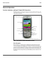
Controls, Indicators, and Input / Output (I/O) Connectors
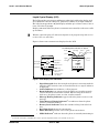
The E365 telephones’ controls are located on the front and side of the device, and
on the keyboard as shown in Figure 1. Indicators, in the form of icons, are displayed
on the LCD (see Figure 2).
Menu Navigation
E365 telephones are equipped with a simplified icon and graphical-based user
interface. The phone also features a user-definable Quick Access menu that is
accessed by holding down the MENU key. See Figure 3 for details of the E365 menu
structure. A 4-way navigation key allows you to move easily through menus. The
4-way navigation key functions as a speaker volume up/down key only during a call.
The 4-way navigation key when pressed UP provides a shortcut to the Quick Access
list. When the 4-way navigation key is pressed DOWN, provides a shortcut to voice
commands.
020111o
Figure 1. E365 Telephone Controls and Indicators Locations
Earpiece Speaker
Camera Key
Left Soft Key
Power/End Key
Keypad
Menu Key
Send Key
Right Soft Key
Accessory Connector
4 way
Navigation Key
Microphone

6809461A68 June 12, 2003 15
Level 1 and 2 Service Manual General Operation
Liquid Crystal Display (LCD)
The LCD provides an 832 square millimeter multicolor backlit color display with
user-adjustable contrast settings for optimum readability in all light conditions.
The large bit-mapped 128 x 96 pixel display includes up to 4 lines of text, 1 line of
icons, and 1 line of prompts.
Display animation makes the phone’s icon menu move smoothly as the user scrolls
up and down.
Figure 2 shows some common icons displayed on the LCD.
• Signal Strength shows the strength of the phone’s connection with the
network. Calls cannot be sent or received when the “no signal” indicator
is displayed.
• In Use Indicator icon indicates a call in progress.
• Roam Indicator icon appears when the phone uses another network
system outside the user’s home network. When leaving the home net-
work area, the phone roams, or seeks, another network.
• Message Waiting Indicator
4
appears when the phone receives a text
message.
• Voice Message Waiting Indicator
4
icon indicates when the phone
receives a voicemail message.
• Battery Level Indicator shows the amount of charge left in the bat-
tery.
• Real Time Clock shows the current time.
• Menu Indicator provides access to the phone’s main menu.
• GPRS Indicator
4
indicates when the phone is currently functioning in
➧
Whether a phone displays all indicators depends on the programming and services
to which the user subscribes.
031453o
Figure 2. E365 Display Icon Indicators
4. Network, subscription and SIM card or service provider dependent feature. Not available in all areas.
Service Provider
Normal Mode
12:00 pm 01/01
PH.BO0 MESSAG
Y59
v
rg
U
G
ck and Date
Menu Indicator
Messages
Media Center
Datebook
Phonebook
Alert Profile
Note:
Your
phone might list
different
features in the
idle dis
p
la
y
.
Soft Key Labels
The following status indicators can appear:
Service Provider
Normal Mode
12:00 pm 01/01
PH.BO0 MESSAG
U
Ä
Y
D
59
v
rg
U
In Use
Signal
Strength
Alert Type
Battery
Level
Roam Message
GPRS
;
G
J
Active
Line

16 June 12, 2003 6809461A68
General Operation E365
GPRS mode.
• Alert Setting Indicator indicates the phones current ringer alert set-
ting.
User Interface Menu Structure
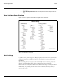
Figure 3 shows a portion of the E365 telephone menu structure.
Alert Settings
In addition to 11 preset ring tones, E365 telephones allow the user to download 2
additional ring tones via SMS to your PC. (Availability is carrier and Network
dependant).
Motorola E365 phones incorporate the VibraCall® discreet vibrating alert that
helps to avoid disturbing others when a ringing phone is unacceptable.
Alerts can be set to ring only, vibrate only, vibrate then ring, or no ring or vibrate
Additionally, the profiling feature allows users to identify incoming calls by a
specific ringer tone.
020250o
Figure 3. E365 Menu Structure
Menu Map
Main Menu
U
Messages *
Create
Inbox
Templates
Outbox
Draft
Voicemail
Message Settings
Voicemail Number
Inbox Setup
Info Alert Setup
Auto Cleanup
-
Games
Magic II
Bowling King
Bubble Tea
Big 2 Garden
Pacific Storm
Sound Setting
z
Alarm
o
Chat *
Start Chat
History
Clear History
:
Quick Access
X
Profile Setting
Normal Mode
Meeting Mode
Outdoor Mode
Handset Mode
Pager Mode
9
Tools
Datebook
Calculator
Fixed Dial
ã
Settings
(see next page)
>
More
r
Phone Book
z
Recent Calls
Received Calls
Dialed Calls
Missed Calls
NotePad
Call Times
Call Cost
v
Media Center
New Picture
Photo Album
Picture
Animation
Melody
VoiceMemo
View Free Space
w
Ring Style
ç
Camera
è
Browser *
'
Voice Memo
Settings Menu
Personalize
Caller Groups
Banner
Wallpaper
Animation
WAP Profile
Set Profile
Set GPRS
Quick Access Setup
Call Forward
Voice Calls
Fax Calls
Data Calls
Cancel All
Phone Status
My Tel. Numbers
Credit Available
Active Line
In Call Setup
In Call Timer
Call Cost Setup
My Caller ID
Call Waiting
Security
Phone Lock
Lock Now
Auto Lock
Unlock Code
Lock Keypad
Fixed Dial
Call Barring
Outgoing Calls
Incoming Calls
Cancel All
SIM PIN
Passwords
Unlock Code
Security Code
SIM PIN
SIM PIN2
Bar Password
Auto Key Lock
Initial Setup
Time and Date
Power on/off
Manual Redial
Backlight
Language
Battery Save
Master Reset
Master Clear
Network
Avail. Networks
Network Setup
* optional network, SIM card, or
subscription-dependent featur
e

6809461A68 June 12, 2003 17
Level 1 and 2 Service Manual General Operation
Battery Function
Battery Charge Indicator
The telephone displays a battery charge indicator icon in the idle screen to indicate
the battery charge level. The gauge shows four levels: 100%, 66%, 33%, and Low
Battery.
Battery Removal
Removing the battery causes the phone to shut down immediately and loose any
pending work (partially entered phone book entries or outgoing messages, for
example).
Operation
For detailed operating instructions, refer to the appropriate User Guide listed in
the Related Publications section toward the end of this manual.
E
All batteries can cause property damage and/or bodily injury such as burns if a
conductive material such as jewelry, keys, or beaded chains touch exposed terminals.
The conductive material may complete an electrical circuit (short circuit) and
become quite hot. Exercise care in handling any charged battery, particularly when
placing it inside a pocket, purse, or other container with metal objects.
G
If the battery is removed while receiving a message, the message is lost.
➧
To ensure proper memory retention, turn the phone OFF before removing the
battery. Immediately replace the old battery with a fresh battery.

18 June 12, 2003 6809461A68
General Operation E365

6809461A68 June 12, 2003 19
Level 1 and 2 Service Manual Tools and Test Equipment
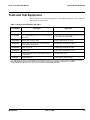
Tools and Test Equipment
Table 1 list the tools and test equipment used on E365 telephones. Use either the
listed items or equivalents.
Table 1. General Test Equipment and Tools
Motorola
Part Number
1
Description Application
See Table 6 Charger Used to charge battery and power phone
0180386A82
Antistatic Mat Kit (includes 66-80387A95 antistatic
mat, 66-80334B36 ground cord, and 42-80385A59
wrist band)
Provides protection from damage to phone caused
by electrostatic discharge (ESD)
8102430Z04 GSM / DCS / PCS Test SIM Used to enable manual test mode
6680388B67 Disassembly tool, plastic with flat and pointed
ends (manual opening tool)
Used during assembly/disassembly
6680388B01 Tweezers, plastic Used during assembly/disassembly
RSX4043-A Torque Driver Used to remove and replace screws
—
Torque Driver Bit T-5 Plus, Apex 440-6IP Torx Plus
or equivalent
Used with torque driver
HP34401A
2
Digital Multimeter Used to measure battery voltage
1. To order in North America, contact Motorola Aftermarket and Accessories Division (AAD) by phone at (800) 422-4210 or
FAX (800) 622-6210; Internationally, AAD can be reached by calling (847) 538-8023 or by fax (847) 576-3023.
2. Not available from Motorola. To order, contact Hewlett Packard at (800) 452-4844.
E365
6809461A68
1 and 2

20 June 12, 2003 6809461A68
Disassembly E365
Disassembly
This section describes how to disassemble an E365 telephone. Tools and equipment
used are listed in Table 1, preceding.
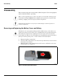
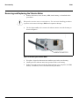
Removing and Replacing the Battery Cover and Battery
1. Ensure the phone is turned off.
2. Press the sides of the battery cover near the top of the battery cover to release
the battery cover latches.
3. Slide the battery cover in the direction of the arrow, and lift the cover away
from the phone (see Figure 4).
G
Many of the integrated devices used in this phone are vulnerable to damage from
electrostatic discharge (ESD). Ensure adequate static protection is in place when
handling, shipping, and servicing any internal components.
G
Avoid stressing the plastic in any way to avoid damage to either the plastic or
internal components.
E
All batteries can cause property damage and/or bodily injury such as burns if a
conductive material such as jewelry, keys, or beaded chains touch exposed terminals.
The conductive material may complete an electrical circuit (short circuit) and
become quite hot. Exercise care in handling any charged battery, particularly when
placing it inside a pocket, purse, or other container with metal objects.
031236o
Figure 1. Removing the Battery Cover
La pagina sta caricando ...
La pagina sta caricando ...
La pagina sta caricando ...
La pagina sta caricando ...
La pagina sta caricando ...
La pagina sta caricando ...
La pagina sta caricando ...
La pagina sta caricando ...
La pagina sta caricando ...
La pagina sta caricando ...
La pagina sta caricando ...
La pagina sta caricando ...
La pagina sta caricando ...
La pagina sta caricando ...
La pagina sta caricando ...
La pagina sta caricando ...
La pagina sta caricando ...
La pagina sta caricando ...
La pagina sta caricando ...
La pagina sta caricando ...
La pagina sta caricando ...
La pagina sta caricando ...
La pagina sta caricando ...
La pagina sta caricando ...
La pagina sta caricando ...
La pagina sta caricando ...
-
 1
1
-
 2
2
-
 3
3
-
 4
4
-
 5
5
-
 6
6
-
 7
7
-
 8
8
-
 9
9
-
 10
10
-
 11
11
-
 12
12
-
 13
13
-
 14
14
-
 15
15
-
 16
16
-
 17
17
-
 18
18
-
 19
19
-
 20
20
-
 21
21
-
 22
22
-
 23
23
-
 24
24
-
 25
25
-
 26
26
-
 27
27
-
 28
28
-
 29
29
-
 30
30
-
 31
31
-
 32
32
-
 33
33
-
 34
34
-
 35
35
-
 36
36
-
 37
37
-
 38
38
-
 39
39
-
 40
40
-
 41
41
-
 42
42
-
 43
43
-
 44
44
-
 45
45
-
 46
46


in altre lingue
- English: Motorola E365 User manual
Documenti correlati
-
Motorola MicroTAC Select 6000e Manuale utente
-
Motorola 9505 Manuale utente
-
Motorola E365 Manuale utente
-
-
-
-
-
-
-
Motorola T720 CDMA Manuale utente