
CAM1000RHD
Turn assist
Installation and Operating Manual . . . . . . 3
Abbiegeassistent
Montage- und Bedienungsanleitung . . . 13
Assistant de changement de
direction
Instructions de montage et de service . . 23
Asistente de giro
Instrucciones de montaje y de uso . . . . .33
Assistente de mudança de direção
Instruções de montagem e manual de
instruções . . . . . . . . . . . . . . . . . . . . . . . . . 43
Assistente di svolta
Istruzioni di montaggio e d’uso . . . . . . . . 53
Draaiassistent
Montagehandleiding en
gebruiksaanwijzing. . . . . . . . . . . . . . . . . . 63
Drejeassistent
Monterings- og betjeningsvejledning. . . 73
Svängassistent
Monterings- och bruksanvisning. . . . . . . 83
Snuhjelp
Monterings- og bruksanvisning . . . . . . . 93
Kääntymisavustin
Asennus- ja käyttöohje. . . . . . . . . . . . . . 103
Система помощи при повороте
Инструкция по монтажу
и эксплуатации. . . . . . . . . . . . . . . . . . . . .113
Asystent skrętu
Instrukcja montażu i obsługi . . . . . . . . . 124
Asistent odbočovania
Návod na montáž a uvedenie
do prevádzky . . . . . . . . . . . . . . . . . . . . . 135
Asistent odbočování
Návod k montáži a obsluze . . . . . . . . . . 145
Fordulássegéd
Szerelési és használati útmutató . . . . . . 155
EN
DE
FR
ES
PT
IT
NL
DA
SV
NO
FI
RU
PL
SK
CS
HU
POWER & CONTROL
PERFECTVIEW VIDEO
SYSTEMS

© 2022 Dometic Group. The visual appearance of the contents of this manual is protected
by copyright and design law. The underlying technical design and the products contained
herein may be protected by design, patent or be patent pending. The trademarks
mentioned in this manual belong to Dometic Sweden AB. All rights are reserved.

CAM1000RHD Explanation of symbols
EN
3
Please read these instructions carefully and follow all instructions, guidelines, and warnings included in this product
manual in order to ensure that you install, use, and maintain the product properly at all times. These instructions
MUST stay with this product.
By using the product, you hereby confirm that you have read all instructions, guidelines, and warnings carefully and
that you understand and agree to abide by the terms and conditions as set forth herein. You agree to use this prod-
uct only for the intended purpose and application and in accordance with the instructions, guidelines, and warn-
ings as set forth in this product manual as well as in accordance with all applicable laws and regulations. A failure to
read and follow the instructions and warnings set forth herein may result in an injury to yourself and others, damage
to your product or damage to other property in the vicinity. This product manual, including the instructions, guide-
lines, and warnings, and related documentation, may be subject to changes and updates. For up-to-date product
information, please visit documents.dometic.com.
Table of contents
1 Explanation of symbols . . . . . . . . . . . . . . . . . . . . . . . . . . . . . . . . . . . . . . . . . . . . . . . . . 3
2 Safety instructions . . . . . . . . . . . . . . . . . . . . . . . . . . . . . . . . . . . . . . . . . . . . . . . . . . . . . 4
3 Scope of delivery . . . . . . . . . . . . . . . . . . . . . . . . . . . . . . . . . . . . . . . . . . . . . . . . . . . . . . 6
4 Intended use . . . . . . . . . . . . . . . . . . . . . . . . . . . . . . . . . . . . . . . . . . . . . . . . . . . . . . . . . 6
5 Technical description . . . . . . . . . . . . . . . . . . . . . . . . . . . . . . . . . . . . . . . . . . . . . . . . . . 7
6 Target group . . . . . . . . . . . . . . . . . . . . . . . . . . . . . . . . . . . . . . . . . . . . . . . . . . . . . . . . . 8
7 Installing the camera . . . . . . . . . . . . . . . . . . . . . . . . . . . . . . . . . . . . . . . . . . . . . . . . . . . 8
8 Connecting the camera. . . . . . . . . . . . . . . . . . . . . . . . . . . . . . . . . . . . . . . . . . . . . . . . . 8
9 Using the camera. . . . . . . . . . . . . . . . . . . . . . . . . . . . . . . . . . . . . . . . . . . . . . . . . . . . . . 9
10 Troubleshooting . . . . . . . . . . . . . . . . . . . . . . . . . . . . . . . . . . . . . . . . . . . . . . . . . . . . . 10
11 Cleaning and maintenance . . . . . . . . . . . . . . . . . . . . . . . . . . . . . . . . . . . . . . . . . . . . . .11
12 Warranty. . . . . . . . . . . . . . . . . . . . . . . . . . . . . . . . . . . . . . . . . . . . . . . . . . . . . . . . . . . . .11
13 Disposal . . . . . . . . . . . . . . . . . . . . . . . . . . . . . . . . . . . . . . . . . . . . . . . . . . . . . . . . . . . . .11
14 Technical data . . . . . . . . . . . . . . . . . . . . . . . . . . . . . . . . . . . . . . . . . . . . . . . . . . . . . . . 12
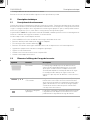
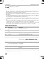
1 Explanation of symbols
DDANGER!
Safety instruction: Indicates a hazardous situation that, if not avoided, will result in
death or serious injury.

Safety instructions CAM1000RHD
EN
4
!
!
A
I
2 Safety instructions
Please observe the prescribed safety instructions and stipulations from the vehicle manufacturer and
service workshops.
Observe the applicable legal regulations.
DDANGER!
• The camera does not release the driver from the duty of care when driving.
• The driver remains fully responsible for driving the vehicle, for fulfilling the road safety
obligations and for complying with the statutory road safety requirements.
!WARNING! Failure to obey these warnings could result in death or serious
injury.
Risk of injury
• Secure the parts installed in the vehicle in such a way that they cannot become loose
under any circumstances (sudden braking, accidents) and cause injuries to the occu-
pants of the vehicle.
• Do not install the parts anywhere in the vehicle where an airbag may open. This can
cause injury if the airbag deploys.
• Inadequate supply line connections can result in short circuits, causing:
–Cable fires
– The airbag being triggered
– Damage to electronic control devices
– Electrical malfunctions (turn signal, stop light, horn, ignition, lights).
!CAUTION! Failure to obey these cautions could result in minor or moderate
injury.
• Secure any parts of the system concealed by the bodywork in such a manner that they
cannot be come loose or damage other parts or cables, or impair vehicle functions
(steering, pedals, etc.).
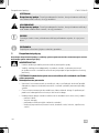
WARNING!
Safety instruction: Indicates a hazardous situation that, if not avoided, could result in
death or serious injury.
CAUTION!
Safety instruction: Indicates a hazardous situation that, if not avoided, could result in
minor or moderate injury.
NOTICE!
Indicates a situation that, if not avoided, can result in property damage.
NOTE
Supplementary information for operating the product.

CAM1000RHD Safety instructions
EN
5
• Always follow the safety instructions of the vehicle manufacturer.
Some work (e.g., on retention systems such as the airbag, etc.) may only be per-
formed by qualified specialists.
ANOTICE!
Damage hazard
• To prevent damage when drilling, ensure that there is sufficient space on the other
side for the drill head to emerge.
• Deburr all drill holes and treat them with a rust-protection agent.
• When working on the electrical system, the batteries must be separated from the
vehicle ground. This applies to the main and additional batteries.
• When working on the following cables, only use insulated cable lugs, plugs and tab
sleeves:
– 30 (direct input from positive battery terminal)
– 15 (connected positive terminal, behind the battery)
– 31 (return cable from the battery, ground)
– 58 (reversing light)
Do not use porcelain wire connectors.
• Use a crimping tool to connect the cables.
• Screw the cable when connecting cable 31 (ground).
– Screw on the cable using a cable lug and gear disc to one of the vehicle's ground
bolts or
– Screw the cable to the sheet metal body work using a cable lug and a self-tapping
screw.
Ensure that there is a good ground connection.
• If you disconnect the battery, all data stored in all volatile memory will be lost. Data
may have to be reset. Please follow the instructions of the respective vehicle manu-
facturer in this case. You can find instructions for making these settings in the operat-
ing manual.
• When testing the voltage in electrical cables, only use a diode test lamp or a
voltmeter.
Test lamps with a bulb consume too much voltage, which can damage the vehicle's
electronic system.
• When making electrical connections, ensure the following:
– They are not kinked or twisted
– They do not rub on edges
– They are not laid in sharp-edged through-holes without protection.
• Insulate all connections.
• Secure the cables against mechanical stress with cable binders or insulating tape,
e.g., to existing lines.
• Follow the installation and operating manual for the monitor.

Scope of delivery CAM1000RHD
EN
6
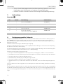
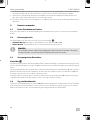
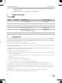
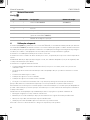
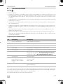
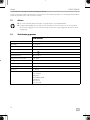
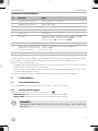
3Scope of delivery
See fig. 1
4 Intended use
The CAM1000RHD camera, together with the M75LXAHD monitor, is the camera-based turn assistant
BVS71000RHD for right-hand-drive vehicles that supports the driver during left-hand turning maneuvers. The cam-
era is designed for installation above the passenger window of the driver's cab and is equipped with a movable
ball head for easy adjustment.
The camera is designed for installation in commercial vehicles.
The camera does not release the driver from the duty of care when turning, in particular the inspection of the area
to the left of the vehicle.
Detection reliability depends on correct installation, sufficient care (removal of dirt) and lighting conditions (min.
10 lux).
The camera has the following system limits:
• The system detects VRU (vulnerable road users) such as pedestrians or cyclists as well as wheelchair users
• The objects may enter the detection area from any direction and may move or may be stationary.
• The system does not detect hidden objects.
• The detection of objects in darkness is limited.
• The detection of objects in strong shadow is limited.
• Objects with a shape close to a human body may generate a detection indication.
This product is only suitable for the intended purpose and application in accordance with these instructions.
This manual provides information that is necessary for proper installation and/or operation of the product. Poor
installation and/or improper operating or maintenance will result in unsatisfactory performance and a possible fail-
ure.
The manufacturer accepts no liability for any injury or damage to the product resulting from:
• Incorrect assembly or connection, including excess voltage
• Incorrect maintenance or use of spare parts other than original spare parts provided by the manufacturer
• Alterations to the product without express permission from the manufacturer
• Use for purposes other than those described in this manual
Dometic reserves the right to change product appearance and product specifications.
No. Quantity Designation Reference number
1 1 Camera CAM1000RHD 9620001012
2 1 Base 9600026951
3 1 Buzzer –
4 1 Camera cable set 9600026950
5 1 Monitor M75LXAHD
(part of system BSV71000RHD)
9600012899
– 1 Installation and operating manual

CAM1000RHD Technical description
EN
7
5 Technical description
5.1 Function description
The camera image is evaluated via the control unit in the camera. Any VRU entering the detection area (region of
interest = ROI) is detected and marked on the monitor with a red movement rectangle. The rectangle moves with
the detected object and serves as an optical signal. Optionally, an acoustic warning device (buzzer, included in the
scope of delivery) can be added.
The system BVS7 1000RHD includes the M75LXAHD monitor, which is preferably mounted on the left A-pillar and
provides the driver with images of the situation next to the vehicle.
The camera has the following features:
• CMOS camera with VRU detection function
• Minimized false detection due to adaptive algorithm
• Defined active and inactive image area (fig. 4)
• Detection and indication of VRU while moving or stationary only
• Optical signaling by dynamic rectangular indicator
• Acoustic warning signal
• Speed-dependent activation via GPS receiver
• Automatic activation of the monitor
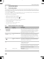
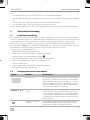
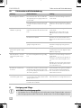
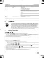
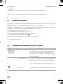
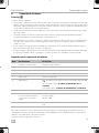
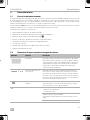
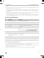
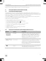
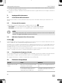
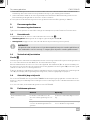
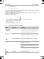
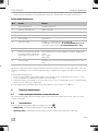
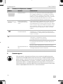
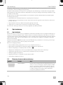
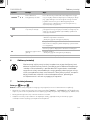
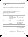
5.2 Display elements of the camera image
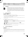
Symbol Function Description
Active area The red field marks the detection range of the camera. It
appears for about 3 seconds after the ignition is switched
on. It indicates the area (ROI) where the camera can detect
an object. This field can be used to adjust the camera so
that its detection range covers a certain area.
Reference line with center
cross
The reference line appears permanently. It shows the line
between active and inactive area. It should preferably be
positioned parallel to the left vehicle contour. The center
cross is the optical center line of the camera and should be
placed vertically below the camera position.
Dynamic rectangular indi-
cator
The dynamic rectangular indicator starts at the detected
object and moves forwards or backwards parallel with the
detected object along the vehicle.
GPS Green symbol:
– Optical display of objects
– Warning sound active
Yellow symbol: No GPS signal
No speed related activation or deactivation of the system.
Red symbol: No object detection available
Warning sound Blue symbol:
– Warning sound inactive
A or BOperation mode Indication of the selected operation mode

Target group CAM1000RHD
EN
8
6 Target group
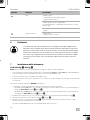
7 Installing the camera
See fig. 2 to fig. 9
Note the following before installation (change acceptance):
• Depending on country-specific regulations, the system BVS71000RHD - CAM1000RHD + M75LXAHD may
require an approval by a testing laboratory (e.g., DEKRA, TÜV).
• Observe the manufacturer's installation guidelines.
• The device may only be put into operation if the user is aware of the risks and dangers resulting from the use of
the device.
Note the following during installation:
• Note the detection range dependent on the position of the camera:
– Operating mode A (red letter “A” on screen) for camera positions with a mounting height from 2m to 3m
(fig. 2 to fig. 4)
– Operating mode B (red letter “B” on screen) for camera positions with a mounting height from 3m to 4m
(fig. 3 to fig. 4)
1. Install the extension base if the box body blocks the view to the detection zone (fig. 5).
2. Install the camera as shown in fig. 6 to fig. 8.
3. Mount the monitor as shown in fig. 9, preferably in the area of the left A-pillar, 30° to the viewing axis straight
ahead.
The NOR/ MIR selection of the monitor is triggered by the yellow/orange wires.
8 Connecting the camera
See fig. 0
Note the following:
• As far as possible, use original ducts for laying the cables, or other suitable options such as paneling edges, ven-
tilation grilles or dummy plugs. If no openings are available, you must drill holes for the respective cables.
Check beforehand that there is sufficient space on the other side for the drill head to emerge.
• Wherever possible, lay cables inside the vehicle as they are better protected there than outside.
• If you do need to lay a cable outside the vehicle, ensure that it is well fastened (use additional cable ties, insu-
lating tape, etc.).
• To prevent damage to the cables when laying them, ensure that they are always far enough away from hot or
moving vehicle components (exhaust pipes, driveshafts, light systems, fans, heaters, etc.).
• Attach the cables securely in the vehicle to prevent tripping hazards. This can be performed by using cable
binders, insulating tape or gluing in place with adhesives.
• Protect every through-hole made in the bodywork against water penetration by suitable measures, e.g. by
using a cable with a sealant and by spraying the cable and the cable sleeve with sealant.
The mechanical and electrical installation and setup of the device must be per-
formed by a qualified technician who has demonstrated skill and knowledge
related to the construction and operation of automotive equipment and instal-
lations, and who is familiar with the applicable regulations of the country in
which the equipment is to be installed and/or used, and has received safety
training to identify and avoid the hazards involved.

CAM1000RHD Using the camera
EN
9
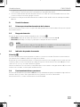
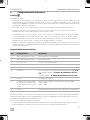
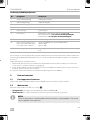
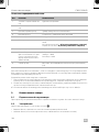
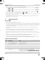
Key for circuit diagram
It is important for the compliant operation of the system that it cannot be switched off manually. The camera must
therefore be connected via camera input CAM3 of the M75LX AHD monitor. The corresponding blue control
cable activates or deactivates the monitor.
The following connections must be implemented:
1. The picture settings provided by the monitor must be completed before connecting the blue cables. After
installation the keys of the monitor are blocked and no settings are available.
2. Connect the blue wire of the camera system cable with the blue CAM3 control cable of the monitor. This con-
nection is used to switch the monitor on/off.
✔The system will automatically be activated and deactivated via the GPS signal at approx. 40 km/h.
9 Using the camera
9.1 Initial start of the camera
On the initial start-up the GPS receiver must save the satellite position. This may take up to 5 minutes.
9.2 Detection range
The detection range of the camera is divided into two zones (fig. 4):
•Visible area: depending on mounting height in operating mode A or B
•Active area (indicated by the red field appearing after activation of the system)
I
No. Designation Description
1 Green connection plug Audio output to loudspeaker
2 Yellow connection plug CVBS video output
3 Red/black wire Buzzer for acoustic signal
4 Red wire Connection to ignition (ACC) 12 V/24 V
5 Green wire No function
6 White wire Cable loop for activation of operation mode A or B:
Not connected to ACC = A (2 m to 3 m installation height)
Connected to ACC = B (3m to 4m installation height)
7 Black wire Connection to ground
8 Yellow / orange wires (to use this
trigger wire as a loop 2 cables
are needed)
Select normal (NOR) or mirrored (MIR) picture:
Closed = NOR
Open = MIR
9 Blue wire GPS output 12 V/24 V for switching on the monitor (blue cable)
(C3)
NOTE
The view of the camera into the detection area must not be obscured by vehicle parts.
Objects may not be detected.

Troubleshooting CAM1000RHD
EN
10
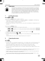
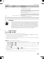
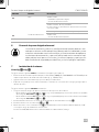
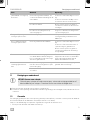
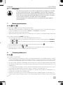
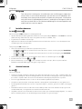
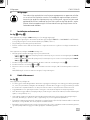
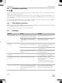
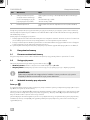
9.3 Test indicator when switching on
See fig. a
The video system switches in standby-mode soon as the ignition is switched on. The system is activated by a speed
of less than 40 km/h. The camera image appears.
The center cross indicator allows the camera to be correctly aligned.The center cross (1) is the optical center line of
the camera and should be placed vertically below the camera position. The active area (2) is marked as a red area
in the video for 6 seconds.
As soon as a VRU enters the active area, the dynamic rectangular indicator (3) appears in the display. If the audible
signal is connected, a beep will sound simultaneously.
9.4 Operation at day and night
The monitor M75LXAHD from the BSV71000RHD system offers adjustment possibilities to adapt the image to day
and night operation. These settings must be made before connecting the blue wires.
For more information, please refer to the manual of the monitor M75LXAHD.
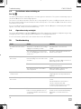
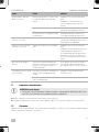
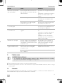
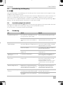
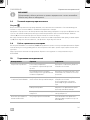
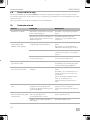
10 Troubleshooting
Fault Cause Solution
The device shows no func-
tion.
The black or red cable for the voltage
supply are not making contact.
Check that the connections are
secure.
The system plug is not connected or
not correctly plugged into the control
electronics.
Check the system plug and make sure
that it locks into place.
NO SIGNAL is displayed on
the monitor.
No video signal present. Loose con-
tact in the plug connector of the cam-
era cable
Check that the connections are
secure.
Especially check the 20p connector of
the monitor power cord.
The camera is defective. Contact an authorized service center
to replace the camera.
The camera was not connected to
camera input C3.
Make sure that the camera is con-
nected to camera input C3.
A yellow GPS icon appears
on the monitor.
GPS reception is faulty. The system is active. The camera
image appears even at speeds above
40 km/h.
A red GPS icon appears on
the monitor.
No object detection is available. Check that the connections are
secure.
Check whether the camera lens is
soiled or otherwise blocked.
Contact an authorized service center
in case no proper function lasts.
The monitor will not turn off. The monitor was turned on manually
before connecting the blue wire. In
connection with the camera the keys
are blocked.
The blue wire must be disconnected
and the monitor switched off manually.
Afterwards connect the blue wire
again.

CAM1000RHD Cleaning and maintenance
EN
11
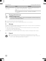
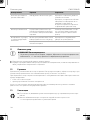
11 Cleaning and maintenance
A
➤Occasionally clean the device with a soft, damp cloth.
➤Regularly check live cables or wires for insulation faults, breaks or loose connections.
12 Warranty
The statutory warranty period applies. If the product is defective, please contact your retailer or the manufacturer's
branch in your country (see dometic.com/dealer).
For repair and warranty processing, please include the following documents when you send in the product:
• A copy of the receipt with purchasing date
• A reason for the claim or description of the fault
Note that self-repair or non-professional repair can have safety consequences and might void the warranty.
13 Disposal
No picture, but the warning
tone sounds.
The monitor receives no video signal.
The camera is connected to the wrong
input.
Check the camera channel used. It
must be C3.
The cinch adapter has a loose contact
or is defective.
Check the cinch adapter.
NOTICE! Damage hazard
• Do not use sharp or hard objects, abrasive cleaning agents or bleach during clean-
ing as these can damage the device.
➤Place the packaging material in the appropriate recycling waste bins wherever possible.
➤Consult a local recycling center or specialist dealer for details about how to dispose of the prod-
uct in accordance with the applicable disposal regulations.
Fault Cause Solution

Technical data CAM1000RHD
EN
12
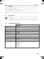
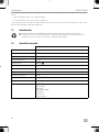
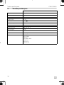
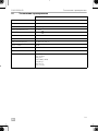
14 Technical data
CAM1000RHD
Image sensor 1/3.2" CMOS
Resolution approx. 1 million
Video format NTSC, 1 Vpp
Light sensitivity < 1 lux
Field of view see fig. 4
Operating voltage 10 V to 36 V
Power consumption max. 6 W
Operating temperature –40 °C to +85 °C
Protection class IP69k
Dimensions 209 x 75 x 58 mm
Weight approx. 0.6 kg
Tests ISO 16750-3
ISO 16750-4
SAE J2527
ECE-R10 05 (2014)
E CISPR 25
ISO 7637-2
FCC Part 15B

CAM1000RHD Erklärung der Symbole
DE
13
Lesen und befolgen Sie bitte alle Anweisungen, Richtlinien und Warnhinweise in diesem Produkthandbuch sorg-
fältig, um sicherzustellen, dass Sie das Produkt ordnungsgemäß installieren und stets ordnungsgemäß betreiben
und warten. Diese Anleitung MUSS bei dem Produkt verbleiben.
Durch die Verwendung des Produktes bestätigen Sie hiermit, dass Sie alle Anweisungen, Richtlinien und Warnhin-
weise sorgfältig gelesen haben und dass Sie die hierin dargelegten Bestimmungen verstanden haben und ihnen
zustimmen. Sie erklären sich damit einverstanden, dieses Produkt nur für den angegebenen Verwendungszweck
und gemäß den Anweisungen, Richtlinien und Warnhinweisen dieses Produkthandbuchs sowie gemäß allen gel-
tenden Gesetzen und Vorschriften zu verwenden. Eine Nichtbeachtung der hierin enthaltenen Anweisungen und
Warnhinweise kann zu einer Verletzung Ihrer selbst und anderer Personen, zu Schäden an Ihrem Produkt oder zu
Schäden an anderem Eigentum in der Umgebung führen. Dieses Produkthandbuch, einschließlich der Anweisun-
gen, Richtlinien und Warnhinweise, sowie die zugehörige Dokumentation können Änderungen und Aktualisierun-
gen unterliegen. Aktuelle Produktinformationen finden Sie unter documents.dometic.com.
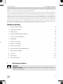
Inhaltsverzeichnis
1 Erklärung der Symbole . . . . . . . . . . . . . . . . . . . . . . . . . . . . . . . . . . . . . . . . . . . . . . . . 13
2 Sicherheitshinweise. . . . . . . . . . . . . . . . . . . . . . . . . . . . . . . . . . . . . . . . . . . . . . . . . . . 14
3 Lieferumfang. . . . . . . . . . . . . . . . . . . . . . . . . . . . . . . . . . . . . . . . . . . . . . . . . . . . . . . . . 16
4 Bestimmungsgemäßer Gebrauch. . . . . . . . . . . . . . . . . . . . . . . . . . . . . . . . . . . . . . . . 16
5 Technische Beschreibung. . . . . . . . . . . . . . . . . . . . . . . . . . . . . . . . . . . . . . . . . . . . . . 17
6 Zielgruppe . . . . . . . . . . . . . . . . . . . . . . . . . . . . . . . . . . . . . . . . . . . . . . . . . . . . . . . . . . 18
7 Kamera montieren . . . . . . . . . . . . . . . . . . . . . . . . . . . . . . . . . . . . . . . . . . . . . . . . . . . . 18
8 Kamera anschließen. . . . . . . . . . . . . . . . . . . . . . . . . . . . . . . . . . . . . . . . . . . . . . . . . . . 19
9 Kamera verwenden . . . . . . . . . . . . . . . . . . . . . . . . . . . . . . . . . . . . . . . . . . . . . . . . . . . 20
10 Fehlersuche und Fehlerbehebung . . . . . . . . . . . . . . . . . . . . . . . . . . . . . . . . . . . . . . . 21
11 Reinigung und Pflege . . . . . . . . . . . . . . . . . . . . . . . . . . . . . . . . . . . . . . . . . . . . . . . . . 21
12 Garantie . . . . . . . . . . . . . . . . . . . . . . . . . . . . . . . . . . . . . . . . . . . . . . . . . . . . . . . . . . . . 22
13 Entsorgung. . . . . . . . . . . . . . . . . . . . . . . . . . . . . . . . . . . . . . . . . . . . . . . . . . . . . . . . . . 22
14 Technische Daten . . . . . . . . . . . . . . . . . . . . . . . . . . . . . . . . . . . . . . . . . . . . . . . . . . . . 22
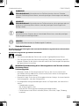
1 Erklärung der Symbole
DGEFAHR!
Safety instruction: Indicates a hazardous situation that, if not avoided, will result in
death or serious injury.

Sicherheitshinweise CAM1000RHD
DE
14
!
!
A
I
2 Sicherheitshinweise
Beachten Sie die vom Fahrzeughersteller und vom Kfz-Handwerk vorgeschriebenen Sicherheitshin-
weise und Auflagen.
Beachten Sie die geltenden gesetzlichen Vorschriften.
DGEFAHR!
• Die Kamera entbindet den Fahrer nicht von der Sorgfaltspflicht beim Fahren.
• Der Fahrer behält die volle Verantwortung für das Führen des Fahrzeugs, die Erfül-
lung der Pflichten für die Verkehrssicherheit und für die Einhaltung der entsprechen-
den gesetzlichen Vorschriften.
!WARNUNG! Nichtbeachtung dieser Warnungen kann zum Tod oder schwerer
Verletzung führen.
Verletzungsgefahr
• Befestigen Sie die im Fahrzeug montierten Teile so, dass sie sich unter keinen
Umständen (scharfes Abbremsen, Verkehrsunfall) lösen und zu Verletzungen der
Fahrzeuginsassen führen können.
• Montieren Sie die Teile nicht im Wirkungsbereich eines Airbags. Ansonsten besteht
Verletzungsgefahr, wenn der Airbag auslöst.
• Unsachgemäße Leitungsverbindungen können zur Folge haben, dass durch Kurz-
schluss:
– Kabelbrände entstehen,
– der Airbag ausgelöst wird,
– elektronische Steuerungseinrichtungen beschädigt werden,
– Fehlfunktionen in der Elektrik auftreten (Blinker, Bremslicht, Hupe, Zündung,
Leuchten).
WARNUNG!
Sicherheitshinweis: Kennzeichnet eine Gefahrensituation, die zum Tod oder
schwerer Verletzung führen könnte, wenn die jeweiligen Anweisungen nicht befolgt
werden.
VORSICHT!
Sicherheitshinweis: Kennzeichnet eine Gefahrensituation, die zu geringer oder mit-
telschwerer Verletzung führen könnte, wenn die jeweiligen Anweisungen nicht
befolgt werden.
ACHTUNG!
Kennzeichnet eine Situation, die zu Sachschäden führen kann, wenn die jeweiligen
Anweisungen nicht befolgt werden.
HINWEIS
Ergänzende Informationen zur Bedienung des Produktes.

CAM1000RHD Sicherheitshinweise
DE
15
!VORSICHT! Nichtbeachtung dieser Hinweise kann zu leichten bis mittel-
schweren Verletzungen führen.
• Befestigen Sie verdeckt unter Verkleidungen anzubringende Teile des Systems so,
dass sie sich nicht lösen oder andere Teile und Leitungen beschädigen und keine
Fahrzeugfunktionen (Lenkung, Pedale usw.) beeinträchtigen können.
• Beachten Sie immer die Sicherheitshinweise des Fahrzeugherstellers.
Einige Arbeiten (z. B. an Rückhaltesystemen wie Airbag usw.) dürfen nur von geschul-
tem Fachpersonal durchgeführt werden.
AACHTUNG!
Beschädigungsgefahr
• Achten Sie beim Bohren auf ausreichenden Freiraum für den Bohreraustritt, um Schä-
den zu vermeiden.
• Entgraten Sie jede Bohrung und behandeln Sie sie mit Rostschutzmittel.
• Bei Arbeiten an der Elektroanlage müssen die Batterien von der Fahrzeugmasse
getrennt sein. Dies gilt sowohl für die Haupt- als auch für die Zusatzbatterien.
• Verwenden Sie bei Arbeiten an den folgenden Leitungen nur isolierte Kabelschuhe,
Stecker und Flachsteckhülsen:
– 30 (direkter Eingang vom Batterie-Pluspol)
– 15 (geschaltetes Plus, hinter Batterie)
– 31 (Rückleitung ab Batterie, Masse)
– 58 (Rückfahrscheinwerfer)
Verwenden Sie keine Lüsterklemmen.
• Verwenden Sie eine Krimpzange zum Verbinden der Kabel.
• Verschrauben Sie das Kabel beim Anschluss von Kabel 31 (Masse)
– unter Verwendung von Kabelschuh und Zahnscheibe mit einer fahrzeugeigenen
Masseschraube oder
– unter Verwendung eines Kabelschuhs und einer Blechschraube mit dem Karosse-
rieblech.
Stellen Sie eine gute Masseverbindung sicher.
• Durch das Abklemmen der Batterie gehen alle im flüchtigen Speicher gespeicherten
Daten verloren. Unter Umständen müssen die Daten zurückgesetzt werden. Bitte fol-
gen Sie in diesem Fall den Anweisungen des Fahrzeugherstellers. Hinweise zum Vor-
nehmen dieser Einstellungen finden Sie in der jeweiligen Bedienungsanleitung.
• Benutzen Sie zum Prüfen der Spannung in elektrischen Leitungen nur eine Dioden-
prüflampe oder ein Voltmeter.
Prüflampen mit einem Leuchtkörper nehmen zu hohe Ströme auf, wodurch die Fahr-
zeugelektronik beschädigt werden kann.
• Achten Sie beim Herstellen der elektrischen Anschlüsse auf Folgendes:
– nicht stark geknickt oder verdreht werden,
– nicht an Kanten scheuern,
– nicht ohne Schutz durch scharfkantige Durchführungen verlegt werden.
• Isolieren Sie alle Verbindungen und Anschlüsse.

Lieferumfang CAM1000RHD
DE
16
• Sichern Sie die Kabel gegen mechanische Beanspruchung, indem Sie sie z. B. mit
Kabelbindern oder Isolierband an vorhandenen Leitungen befestigen.
• Beachten Sie beim Einbau des Monitors die Montage- und Bedienungsanleitung.
3Lieferumfang
Siehe Abb. 1
4 Bestimmungsgemäßer Gebrauch
Die Kamera CAM1000RHD ist zusammen mit dem Monitor M75LXAHD der kamerabasierte Abbiegeassistent
BVS71000RHD für rechtsgelenkte Fahrzeuge, der den Fahrer bei Links-Abbiegevorgängen unterstützt. Die
Kamera ist für die Montage oberhalb des Beifahrerfensters vorgesehen und zur einfachen Justierung mit einem
Kugelgelenk versehen.
Die Kamera ist für die Montage in Nutzfahrzeugen ausgelegt.
Die Kamera entbindet den Fahrer nicht von der Sorgfaltspflicht beim Abbiegen, insbesondere die Überprüfung
des Bereiches links neben dem Fahrzeug.
Die Zuverlässigkeit der Erkennungsfunktion ist von der ordnungsgemäßen Montage, ausreichenden Pflege (Ent-
fernen von Schmutz) und den Lichtverhältnissen (min. 10 Lux) abhängig.
Die Kamera weist folgende Systemgrenzen auf:
• Das System erkennt VRU (gefährdete Verkehrsteilnehmer) wie Fußgänger, Radfahrer sowie Rollstuhlfahrer
• Die Objekte können aus jeder Richtung in den Erfassungsbereich eintreten und sich bewegen oder stillstehen.
• Das System kann keine verdeckten Objekte erkennen.
• Bei Dunkelheit ist die Erkennung von Objekten eingeschränkt.
• Bei starken Schatten ist die Erkennung von Objekten eingeschränkt.
• Objekte mit einer Form, die dem menschlichen Körper stark ähnelt, können eine Erkennungsanzeige erzeu-
gen.
Dieses Produkt ist nur für den angegebenen Verwendungszweck und die Anwendung gemäß dieser Anleitung
geeignet.
Dieses Handbuch enthält Informationen, die für die ordnungsgemäße Installation und/oder den ordnungsgemä-
ßen Betrieb des Produkts erforderlich sind. Installationsfehler und/oder ein nicht ordnungsgemäßer Betrieb oder
eine nicht ordnungsgemäße Wartung haben eine unzureichende Leistung und u. U. einen Ausfall des Geräts zur
Folge.
Pos. Anzahl Bezeichnung Artikelnummer
1 1 Kamera CAM1000RHD 9620001012
2 1 Halterung 9600026951
3 1 Summer –
4 1 Kamera-Kabelsatz 9600026950
5 1 Monitor M75LXAHD
(gehört zum System BSV71000RHD)
9600012899
– 1 Montage- und Bedienungsanleitung

CAM1000RHD Technische Beschreibung
DE
17
Der Hersteller übernimmt keine Haftung für Verletzungen oder Schäden am Produkt, die durch Folgendes entste-
hen:
• Unsachgemäße Montage oder falscher Anschluss, einschließlich Überspannung
• Unsachgemäße Wartung oder Verwendung von anderen als den vom Hersteller gelieferten Original-Ersatztei-
len
• Veränderungen am Produkt ohne ausdrückliche Genehmigung des Herstellers
• Verwendung für andere als die in der Anleitung beschriebenen Zwecke
Dometic behält sich das Recht vor, das Erscheinungsbild des Produkts und dessen technische Daten zu ändern.
5 Technische Beschreibung
5.1 Funktionsbeschreibung
Das erfasste Bild wird durch die Steuereinheit in der Kamera ausgewertet. Jeder VRU, der in den Erkennungsbe-
reich eintritt (Untersuchungsbereich = ROI), wird erkannt und auf dem Monitor mit einem roten Bewegungsrecht-
eck gekennzeichnet. Das Rechteck bewegt sich mit dem erkannten Objekt und dient als optisches Signal.
Optional kann eine akustische Warnvorrichtung (Summer, im Lieferumfang enthalten) hinzugefügt werden.
Zum System BVS7 1000RHD gehört der Monitor M75LXAHD, der vorzugsweise an der linken A-Säule montiert
wird und auf dem sich der Fahrer über die Situation neben dem Fahrzeug informieren kann.
Die Kamera weist folgende Merkmale auf:
• CMOS-Kamera mit VRU-Erkennungsfunktion
• Minimierung von Fehlerkennung durch adaptiven Algorithmus
• Definierter aktiver und inaktiver Bildbereich (Abb. 4)
• Erkennung und Anzeige von VRU nur bei Bewegung oder Stillstand
• Optische Signalgebung durch dynamisches Anzeigerechteck
• Akustisches Warnsignal
• Geschwindigkeitsabhängige Aktivierung per GPS-Empfänger
• Automatische Aktivierung des Monitors
5.2 Anzeigeelemente des Kamerabildes
Symbol Funktion Beschreibung
Aktiver Bereich Das rote Feld markiert den Erfassungsbereich der Kamera.
Es wird für ca. 3 Sekunden nach dem Einschalten der Zün-
dung angezeigt. Es gibt den Bereich (ROI) an, in dem die
Kamera ein Objekt erkennen kann. Mithilfe dieses Feldes
lässt sich die Kamera so justieren, dass der Erfassungsbe-
reich einen bestimmten Bereich abdeckt.
Bezugslinie mit Mittel-
kreuz
Die Bezugslinie wird ständig angezeigt. Sie zeigt die
Grenze zwischen aktivem und inaktivem Bereich an. Sie
sollte vorzugsweise parallel zur linken Fahrzeugkontur aus-
gerichtet werden. Das Mittelkreuz ist die optische Mittelli-
nie der Kamera und sollte vertikal unter der Kameraposition
platziert werden.
Dynamisches Anzeige-
rechteck
Das dynamische Anzeigerechteck beginnt am erkannten
Objekt und bewegt sich parallel zum erkannten Objekt
entlang des Fahrzeugs vorwärts oder rückwärts.

Zielgruppe CAM1000RHD
DE
18
6 Zielgruppe
7 Kamera montieren
Siehe Abb. 2 bis Abb. 9
Vor der Montage (Änderungsabnahme) ist Folgendes zu beachten:
• Je nach länderspezifischen Vorschriften kann für das System BVS71000RHD - CAM1000RHD + M75LXAHD
eine Abnahme durch eine Prüfstelle (z. B. DEKRA, TÜV) erforderlich sein.
• Bitte beachten Sie die Montagerichtlinien des Herstellers.
• Das Gerät darf nur dann in Betrieb genommen werden, wenn sich der Anwender über die damit einhergehen-
den Risiken und Gefahren im Klaren ist.
Während der Montage ist Folgendes zu beachten:
• Beachten Sie den von der Position der Kamera abhängigen Erfassungsbereich:
– Betriebsart A (roter Buchstabe „A“ auf der Anzeige) für Kamerapositionen mit einer Montagehöhe von 2m
bis 3 m (Abb. 2 bis Abb. 4)
– Betriebsart B (roter Buchstabe „B“ auf der Anzeige) für Kamerapositionen mit einer Montagehöhe von 3m
bis 4 m (Abb. 3 bis Abb. 4)
1. Montieren Sie die Halterung zur Verlängerung, wenn der Kofferaufbau die Sicht auf den Erfassungsbereich
versperrt (Abb. 5).
2. Montieren Sie die Kamera wie in Abb. 6 bis Abb. 8 gezeigt.
3. Montieren Sie den Monitor wie in Abb. 9 gezeigt, vorzugsweise im Bereich der linken A-Säule, 30° zur Blick-
achse geradeaus.
Die Auswahl von NOR/MIR des Monitors wird durch die gelben/orangefarbenen Adern ausgelöst.
GPS Grünes Symbol:
– optische Anzeige von Objekten
– akustisches Warnsignal aktiviert
Gelbes Symbol: Kein GPS-Signal
Keine geschwindigkeitsabhängige Aktivierung oder Deak-
tivierung des Systems.
Rotes Symbol: Keine Objekterkennung verfügbar
Akustisches Warnsignal Blaues Symbol:
– akustisches Warnsignal deaktiviert
A oder BBetriebsart Anzeige der gewählten Betriebsart
Die mechanische und elektrische Installation und Einrichtung des Geräts müs-
sen von einer qualifizierten Fachkraft durchgeführt werden, die ihre Fähigkei-
ten und Kenntnisse im Zusammenhang mit dem Aufbau und der Bedienung
von Kfz-Anlagen und -Installationen unter Beweis gestellt hat und die mit den
geltenden Vorschriften des Landes, in dem das Gerät installiert und/oder ver-
wendet werden soll, vertraut ist und eine Sicherheitsschulung erhalten hat, um
die damit verbundenen Gefahren zu erkennen und zu vermeiden.
Symbol Funktion Beschreibung

CAM1000RHD Kamera anschließen
DE
19
8 Kamera anschließen
Siehe Abb. 0
Bitte beachten Sie Folgendes:
• Nutzen Sie beim Verlegen der Anschlusskabel nach Möglichkeit Original-Kabelführungen oder andere geeig-
nete Optionen, z. B. Verkleidungskanten, Lüftungsgitter oder Blindstopfen. Wenn keine Durchführungen vor-
handen sind, müssen Sie für die jeweiligen Kabel entsprechende Löcher bohren. Schauen Sie vorher nach, ob
ausreichender Freiraum für den Bohreraustritt vorhanden ist.
• Verlegen Sie die Kabel nach Möglichkeit immer im Fahrzeuginneren, denn dort sind sie besser geschützt als
außen am Fahrzeug.
• Wenn Sie die Kabel trotzdem außerhalb des Fahrzeuges verlegen, achten Sie auf eine sichere Befestigung
(durch zusätzliche Kabelbinder, Isolierband usw.).
• Um Beschädigungen an den Kabeln zu vermeiden, halten Sie beim Verlegen der Kabel immer ausreichend
Abstand zu heißen und beweglichen Fahrzeugteilen (Auspuffrohre, Antriebswellen, Lichtmaschinen, Lüfter,
Heizungen usw.).
• Befestigen Sie die Kabel sicher im Fahrzeug, um ein Verfangen (Sturzgefahr) zu vermeiden. Dies kann mithilfe
von Kabelbindern oder Isolierband oder auch durch Ankleben mit Klebstoff erreicht werden.
• Machen Sie jede Durchführung an der Karosse durch geeignete Maßnahmen wasserdicht, z. B. durch Einset-
zen des Kabels mit Dichtungsmasse und durch Besprühen des Kabels und der Kabeltülle mit einem Dichtungs-
mittel.
Legende zum Schaltplan
Es ist wichtig für den regelkonformen Betrieb des Systems, dass es nicht manuell ausgeschaltet werden kann. Die
Kamera muss deshalb über den Kameraeingang CAM3 des Monitors M75LX AHD angeschlossen werden. Das
entsprechende blaue Steuerkabel aktiviert oder deaktiviert den Monitor.
Die folgenden Verbindungen müssen hergestellt werden:
Pos. Bezeichnung Beschreibung
1 Grüner Anschlussstecker Audioausgang zum Lautsprecher
2 Gelber Anschlussstecker CVBS-Videoausgang
3 Rote/schwarze Ader Summer für akustisches Warnsignal
4 Rote Ader Verbindung zur Zündung (ACC) 12 V/24 V
5 Grüne Ader Keine Funktion
6 Weiße Ader Kabelschleife zum Aktivieren der Betriebsart A oder B:
Nicht mit ACC verbunden = A (Einbauhöhe 2m bis 3m)
Mit ACC verbunden = B (Einbauhöhe 3 m bis 4 m)
7 Schwarze Ader Masseverbindung
8 Gelbe/orangefarbene Adern
(um diese Auslöseader als
Schleife zu verwenden, sind
2 Kabel erforderlich)
Wählen Sie das normale (NOR) oder gespiegelte (MIR) Bild aus:
Geschlossen = NOR
Geöffnet = MIR
9 Blaue Ader GPS-Ausgang 12 V/24 V zum Einschalten des Monitors (blaues
Kabel) (C3)

Kamera verwenden CAM1000RHD
DE
20
1. Die Bildeinstellungen des Monitors müssen vor dem Anschließen der blauen Kabel vorgenommen werden.
Nach der Montage sind die Tasten des Monitors gesperrt und es sind keine Einstellungen verfügbar.
2. Verbinden Sie die blaue Ader des Kamerasystemkabels mit dem blauen CAM3-Steuerkabel des Monitors.
Über diese Verbindung wird der Monitor ein- und ausgeschaltet.
✔Das System wird bei einer Geschwindigkeit von ca. 40 km/h automatisch durch das GPS-Signal aktiviert bzw.
deaktiviert.
9 Kamera verwenden
9.1 Erstes Einschalten der Kamera
Beim ersten Einschalten muss der GPS-Empfänger die Satellitenposition speichern. Dies kann bis zu 5 Minuten
dauern.
9.2 Erfassungsbereich
Der Erfassungsbereich der Kamera ist in zwei Zonen unterteilt (Abb. 4):
•Sichtbarer Bereich: abhängig von der Einbauhöhe in der Betriebsart A oder B
•Aktiver Bereich: (angezeigt durch das rote Feld nach Aktivierung des Systems)
I
9.3 Testanzeige beim Einschalten
Siehe Abb. a
Das Videosystem schaltet in den Bereitschaftszustand, sobald die Zündung eingeschaltet wird. Das System wird
bei einer Geschwindigkeit von weniger als 40 km/h aktiviert. Das von der Kamera aufgenommene Bild wird ange-
zeigt.
Das angezeigte Mittelkreuz ermöglicht die korrekte Ausrichtung der Kamera. Das Mittelkreuz (1) ist die optische
Mittellinie der Kamera und sollte vertikal unter der Kameraposition platziert werden. Der aktive Bereich (2) wird
6 Sekunden lang im Video als roter Bereich gekennzeichnet.
Sobald ein VRU in den aktiven Bereich eintritt, wird das dynamische Anzeigerechteck (3) auf der Anzeige ange-
zeigt. Wenn das akustische Signal angeschlossen ist, ertönt gleichzeitig ein Piepton.
9.4 Tag- und Nachtbetrieb
Der Monitor M75LXAHD des Systems BSV71000RHD bietet die Möglichkeit, das Bild auf den Tag- oder Nachtbe-
trieb einzustellen. Diese Einstellungen sind vorzunehmen, bevor die blauen Leitungen angeschlossen werden.
Weitere Informationen finden Sie in der Bedienungsanleitung für den Monitor M75LXAHD.
HINWEIS
Die Sicht der Kamera in den Erfassungsbereich darf nicht durch Teile des Fahrzeugs
versperrt werden. Ansonsten können Objekte nicht erkannt werden.
La pagina si sta caricando...
La pagina si sta caricando...
La pagina si sta caricando...
La pagina si sta caricando...
La pagina si sta caricando...
La pagina si sta caricando...
La pagina si sta caricando...
La pagina si sta caricando...
La pagina si sta caricando...
La pagina si sta caricando...
La pagina si sta caricando...
La pagina si sta caricando...
La pagina si sta caricando...
La pagina si sta caricando...
La pagina si sta caricando...
La pagina si sta caricando...
La pagina si sta caricando...
La pagina si sta caricando...
La pagina si sta caricando...
La pagina si sta caricando...
La pagina si sta caricando...
La pagina si sta caricando...
La pagina si sta caricando...
La pagina si sta caricando...
La pagina si sta caricando...
La pagina si sta caricando...
La pagina si sta caricando...
La pagina si sta caricando...
La pagina si sta caricando...
La pagina si sta caricando...
La pagina si sta caricando...
La pagina si sta caricando...
La pagina si sta caricando...
La pagina si sta caricando...
La pagina si sta caricando...
La pagina si sta caricando...
La pagina si sta caricando...
La pagina si sta caricando...
La pagina si sta caricando...
La pagina si sta caricando...
La pagina si sta caricando...
La pagina si sta caricando...
La pagina si sta caricando...
La pagina si sta caricando...
La pagina si sta caricando...
La pagina si sta caricando...
La pagina si sta caricando...
La pagina si sta caricando...
La pagina si sta caricando...
La pagina si sta caricando...
La pagina si sta caricando...
La pagina si sta caricando...
La pagina si sta caricando...
La pagina si sta caricando...
La pagina si sta caricando...
La pagina si sta caricando...
La pagina si sta caricando...
La pagina si sta caricando...
La pagina si sta caricando...
La pagina si sta caricando...
La pagina si sta caricando...
La pagina si sta caricando...
La pagina si sta caricando...
La pagina si sta caricando...
La pagina si sta caricando...
La pagina si sta caricando...
La pagina si sta caricando...
La pagina si sta caricando...
La pagina si sta caricando...
La pagina si sta caricando...
La pagina si sta caricando...
La pagina si sta caricando...
La pagina si sta caricando...
La pagina si sta caricando...
La pagina si sta caricando...
La pagina si sta caricando...
La pagina si sta caricando...
La pagina si sta caricando...
La pagina si sta caricando...
La pagina si sta caricando...
La pagina si sta caricando...
La pagina si sta caricando...
La pagina si sta caricando...
La pagina si sta caricando...
La pagina si sta caricando...
La pagina si sta caricando...
La pagina si sta caricando...
La pagina si sta caricando...
La pagina si sta caricando...
La pagina si sta caricando...
La pagina si sta caricando...
La pagina si sta caricando...
La pagina si sta caricando...
La pagina si sta caricando...
La pagina si sta caricando...
La pagina si sta caricando...
La pagina si sta caricando...
La pagina si sta caricando...
La pagina si sta caricando...
La pagina si sta caricando...
La pagina si sta caricando...
La pagina si sta caricando...
La pagina si sta caricando...
La pagina si sta caricando...
La pagina si sta caricando...
La pagina si sta caricando...
La pagina si sta caricando...
La pagina si sta caricando...
La pagina si sta caricando...
La pagina si sta caricando...
La pagina si sta caricando...
La pagina si sta caricando...
La pagina si sta caricando...
La pagina si sta caricando...
La pagina si sta caricando...
La pagina si sta caricando...
La pagina si sta caricando...
La pagina si sta caricando...
La pagina si sta caricando...
La pagina si sta caricando...
La pagina si sta caricando...
La pagina si sta caricando...
La pagina si sta caricando...
La pagina si sta caricando...
La pagina si sta caricando...
La pagina si sta caricando...
La pagina si sta caricando...
La pagina si sta caricando...
La pagina si sta caricando...
La pagina si sta caricando...
La pagina si sta caricando...
La pagina si sta caricando...
La pagina si sta caricando...
La pagina si sta caricando...
La pagina si sta caricando...
La pagina si sta caricando...
La pagina si sta caricando...
La pagina si sta caricando...
La pagina si sta caricando...
La pagina si sta caricando...
La pagina si sta caricando...
La pagina si sta caricando...
La pagina si sta caricando...
La pagina si sta caricando...
La pagina si sta caricando...
La pagina si sta caricando...
La pagina si sta caricando...
La pagina si sta caricando...
-
 1
1
-
 2
2
-
 3
3
-
 4
4
-
 5
5
-
 6
6
-
 7
7
-
 8
8
-
 9
9
-
 10
10
-
 11
11
-
 12
12
-
 13
13
-
 14
14
-
 15
15
-
 16
16
-
 17
17
-
 18
18
-
 19
19
-
 20
20
-
 21
21
-
 22
22
-
 23
23
-
 24
24
-
 25
25
-
 26
26
-
 27
27
-
 28
28
-
 29
29
-
 30
30
-
 31
31
-
 32
32
-
 33
33
-
 34
34
-
 35
35
-
 36
36
-
 37
37
-
 38
38
-
 39
39
-
 40
40
-
 41
41
-
 42
42
-
 43
43
-
 44
44
-
 45
45
-
 46
46
-
 47
47
-
 48
48
-
 49
49
-
 50
50
-
 51
51
-
 52
52
-
 53
53
-
 54
54
-
 55
55
-
 56
56
-
 57
57
-
 58
58
-
 59
59
-
 60
60
-
 61
61
-
 62
62
-
 63
63
-
 64
64
-
 65
65
-
 66
66
-
 67
67
-
 68
68
-
 69
69
-
 70
70
-
 71
71
-
 72
72
-
 73
73
-
 74
74
-
 75
75
-
 76
76
-
 77
77
-
 78
78
-
 79
79
-
 80
80
-
 81
81
-
 82
82
-
 83
83
-
 84
84
-
 85
85
-
 86
86
-
 87
87
-
 88
88
-
 89
89
-
 90
90
-
 91
91
-
 92
92
-
 93
93
-
 94
94
-
 95
95
-
 96
96
-
 97
97
-
 98
98
-
 99
99
-
 100
100
-
 101
101
-
 102
102
-
 103
103
-
 104
104
-
 105
105
-
 106
106
-
 107
107
-
 108
108
-
 109
109
-
 110
110
-
 111
111
-
 112
112
-
 113
113
-
 114
114
-
 115
115
-
 116
116
-
 117
117
-
 118
118
-
 119
119
-
 120
120
-
 121
121
-
 122
122
-
 123
123
-
 124
124
-
 125
125
-
 126
126
-
 127
127
-
 128
128
-
 129
129
-
 130
130
-
 131
131
-
 132
132
-
 133
133
-
 134
134
-
 135
135
-
 136
136
-
 137
137
-
 138
138
-
 139
139
-
 140
140
-
 141
141
-
 142
142
-
 143
143
-
 144
144
-
 145
145
-
 146
146
-
 147
147
-
 148
148
-
 149
149
-
 150
150
-
 151
151
-
 152
152
-
 153
153
-
 154
154
-
 155
155
-
 156
156
-
 157
157
-
 158
158
-
 159
159
-
 160
160
-
 161
161
-
 162
162
-
 163
163
-
 164
164
-
 165
165
-
 166
166
-
 167
167
-
 168
168


in altre lingue
- français: Dometic CAM1000RHD Manuel utilisateur
- Nederlands: Dometic CAM1000RHD Handleiding
- português: Dometic CAM1000RHD Manual do usuário
- slovenčina: Dometic CAM1000RHD Používateľská príručka
- dansk: Dometic CAM1000RHD Brugermanual

