Weller C-WXP200 Manuale del proprietario
- Categoria
- Saldatori
- Tipo
- Manuale del proprietario

WXP 200
Betriebsanleitung - Operating Instructions - Manual de uso - Mode d'emploi - Istruzioni per lùso -
Manual do utilizador


WX 200 – Operating Instructions I
The data specified above only serves
to describe the product. No statements
concerning a certain condition or suitability for
a certain application can be derived from our
information. The given information does not
release the user from the obligation of own
judgement and verification. It must be
remembered that our products are subject to a
natural process of wear and aging.
© This document, as well as the data,
specifications and other information set forth
in it, are the exclusive property of Cooper
Tools GmbH. Without their consent it may not
be reproduced or given to third parties.
Subject to modifications.
Printed in Germany.
10.2010
Deutsch
DE
English
EN
Español
ES
Français
FR
Italiano
IT
Português
PT

WR 3M II

EN FR IT ES PT NL SV DK FI GR TR CZ PL HU SK SL EE LV LT DE
WXP 200
Betriebsanleitung

WXP 200
WXP 200
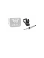
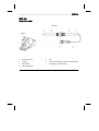
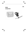
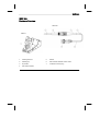
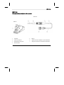
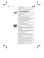
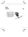
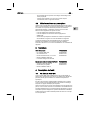
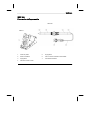
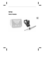
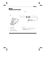
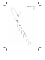
Geräteübersicht
1. Reinigungseinsatz 5. Grif
f
2. Lötspitze 6. Temperaturbeständige antistatische Silikonleitung
3. Spitzenhalte
r
7. Veriegelbarer Anschlußstecke
r
4. LED Statusanzeige
WDH 31
WXP 200

WXP 200 3-8
DE EN FR IT ES PT NL SV DK FI GR TR CZ PL HU SK SL EE LV LT
Inhaltsverzeichnis
1Zu dieser Anleitung .................................................................... 3
2Zu Ihrer Sicherheit ..................................................................... 3
3Lieferumfang .............................................................................. 5
4Gerätebeschreibung .................................................................. 5
5Inbetriebnahme des Gerätes ..................................................... 6
6Wechsel der WXP 120 Lötspitzen ............................................. 7
7Zubehör ..................................................................................... 8
8Entsorgung ................................................................................ 8
9Garantie ..................................................................................... 8
1 Zu dieser Anleitung
Wir danken Ihnen für das mit dem Kauf des Weller Lötkolbens
WXP 2000 erwiesene Vertrauen. Bei der Fertigung wurden strengste
Qualitätsanforderungen zugrunde gelegt, die eine einwandfreie
Funktion des Gerätes sicherstellen.
Diese Anleitung enthält wichtige Informationen, um den Lötkolben
WXP 200 sicher und sachgerecht in Betrieb zu nehmen, zu
bedienen, zu warten und einfache Störungen selbst zu beseitigen.
Z Lesen Sie diese Anleitung und die beiliegenden
Sicherheitshinweise vor Inbetriebnahme des Lötkolbens
WXP 200 durch.
Z Bewahren Sie diese Anleitung so auf, dass sie für alle Benutzer
zugänglich ist.
1.1 Einzuhaltende Richtlinien
Der Weller Lötkolben WXP 200 entspricht der EG-
Konformitätserklärung gemäß den grundlegenden
Sicherheitsanforderungen der Richtlinien 2004/108/EG und
2006/95/EG.
1.2 Geltende Unterlagen
− Betriebsanleitung für Ihre Versorgungseinheit
− Betriebsanleitungen für WXP 200
− Beiliegendes Heft zur Sicherheit
2 Zu Ihrer Sicherheit
− Der Lötkolben WXP 200 wurde nach dem neuesten Stand der
Technik und anerkannten Sicherheitsregeln und -bestimmungen
entsprechend hergestellt.
− Bei Nichtbeachtung der beiliegenden Sicherheitsinformationen
und aufgeführten Warnhinweise besteht jedoch die Gefahr von
Personen- und Sachschäden.

4-8 WXP 200
− Geben Sie den WXP 200 Lötkolben nur zusammen mit dieser
Betriebsanleitung weiter.
− Der Hersteller ist nicht haftbar für Schäden, die aus einer
unsachgemäßen Verwendung des Werkzeugs oder unerlaubten
Veränderungen am Gerät entstehen.
2.1 Beachten Sie bitte Folgendes:
Allgemeine
Hinweise
− Legen Sie den Lötkolben WXP 200 immer in die vorgesehene
Sicherheitsablage.
− Entfernen Sie alle entzündbaren Objekte aus der Nähe des
heißen Lötwerkzeugs.
− Tragen Sie bei der Arbeit mit WXP 200 entsprechende
Schutzkleidung.
− Lassen Sie den heißen WXP 200 nie unbeaufsichtigt.
− Führen Sie keine Arbeiten an unter Spannung stehenden Teilen
aus.
− Antistatische Kunststoffe sind zur Verhinderung von statischen
Ladungen mit leitenden Füllstoffen versehen. Dadurch sind auch
die Isoliereigenschaften des Kunststoffes vermindert.
Führen Sie keine Arbeiten an unter Spannung stehenden Teilen
aus.
− Tragen Sie bei Löt- oder Entlötanwendungen immer einen
Augenschutz.
− Lesen und beachten Sie die Betriebsanleitung der jeweiligen
verwendeten Weller WX Versorgungseinheit
Umgang mit
Löt-/
Entlöt-
spitzen
− Legen Sie heiße Löt- oder Entlötspitzen weder auf die
A
rbeitsfläche oder auf Kunststoffflächen noch lassen Sie sie dort
zurück.
− Benetzen Sie beim ersten Aufheizen des Kolbens die verzinnten
Löt-/Entlötspitzen mit Lot, wodurch lagerbedingte Oxidschichten
oder Unreinheiten von den Löt- bzw. Entlötspitzen entfernt
werden.
− Vergewissern Sie sich, dass bei Arbeitsunterbrechungen
zwischen Löten und Entlöten sowie vor der Lagerung des
Gerätes die Löt-/Entlötspitzen gut benetzt sind.
− Verwenden Sie keine aggressiven Flussmittel.
− Immer darauf achten, dass die Löt-/Entlötspitzen
ordnungsgemäß sitzen.
− Wählen Sie die möglichst geringste Arbeitstemperatur.
− Wählen Sie die möglichst größte Löt-/Entlötspitzenform für die
Anwendung: ca. so groß wie das Lötpad.
− Benetzen Sie die Löt-/Entlötspitzen gut, um effiziente
Wärmeübertragung zwischen Löt-/Entlötspitzen und Lötpunkt zu
gewährleisten.
− Schalten Sie das System ab, wenn Sie das Löt-/Entlötwerkzeug
über längere Zeit nicht verwenden möchten.
− Benetzen Sie die Spitzen vor Ablegen des Löt-/Entlötwerkzeugs
in der Sicherheitsablage.
− Geben Sie das Lot direkt auf die Lötstelle, nicht auf die Löt-/
Entlötspitzen.
− Wenden Sie auf die Löt-/Entlötspitzen keine übermäßige Kraft
an.

WXP 200 5-8
DE EN FR IT ES PT NL SV DK FI GR TR CZ PL HU SK SL EE LV LT
− Immer darauf achten, dass der Lötkolben ordnungsgemäß in der
Sicherheitsablage liegt.
2.2 Bestimmungsgemäßer Gebrauch
Verwenden Sie den WXP 200 Lötkolben ausschließlich für den in
der Betriebsanleitung bezüglich Lösen, Verstauung und Ablage von
elektronischen Bauteilen angegebenen Zweck unter den hier
beschriebenen Bedingungen. Der bestimmungsgemäße Gebrauch
des Lötkolbens WXP 200 beinhaltet auch, dass
− Sie diese Anleitung beachten,
− Sie alle weiteren Begleitunterlagen beachten,
− Sie die nationalen Unfallverhütungsvorschriften am Einsatzort
beachten.
Der Hersteller übernimmt keine Haftung für Schäden, die aus
unsachgemäßem, nicht dem in der Betriebsanleitung beschriebenen
Gebrauch oder unerlaubten Änderungen am Gerät resultieren.
3 Lieferumfang
WXP 200 verpackt T0052920599:
− WXP 200 Lötkolben, T0052920599
− Einmaulschlüssel SW 17 T0058741753
− XHT D Meißelspitze 5 X 1,2 mm T0054480199
− Betriebsanleitung WXP 200
− Heft Sicherheitshinweise
Zusätzlich beim WXP 200 Lötset T0052920699:
− WDH 31 Sicherheitsablage T0051515898
− Steckverbinder für Fußplatte T0058703153
− Betriebsanleitung WDC 2
4 Gerätebeschreibung
4.1 Lötkolben WXP 200
Der WXP 200 Lötkolben zeichnet sich durch ein schnelles und
präzises Erreichen der Lötspitzentemperatur aus. Aufgrund seines
besonders leistungsfähigen 200 W Heizelementes wird ein
ausgezeichnetes dynamisches Verhalten erreicht. Zusammen mit
der schlanken Bauform und der kurzen Distanz vom Griff zur
Lötspitze findet dieser Lötkolben universellen Einsatz von extrem
feinen Lötarbeiten, bis hin zu solchen mit erhöhtem Wärmebedarf.
Auf Grund einer zusätzlichen optimierten Sensorposition ist dieser
Lötkolben besonders für Lötarbeiten mit erhöhter Wärmezufuhr
geeignet. Der WXP 200 ist mit einer Nutzungserkennung
ausgestattet und kann bei Nichtgebrauch automatisch in
Standbybetrieb bzw. Aus geschaltet werden. Durch die LED
Statusanzeige wird der jeweilige Betriebszustand angezeigt. Das
Einstellen der Standbytemperatur sowie die Schaltzeiten entnehmen
Sie bitte der Betriebsanleitung der jeweils verwendeten WX
Versorgungseinheit.

6-8 WXP 200
Hinweis Der Lötkolben WXP 200 von Weller darf nur mit den
Weller WX Versorgungseinheiten betrieben werden.
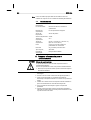
4.2 Technische Daten
Temperaturbereich 100°C - 450°C (212°F - 850°F)
Werkzeugkabel Silikonkautschuk, hitzebeständig
Heizelement Integriertes Heizdrahtelement
Temperatursenso
r
Platinsenso
r
Heizleistung 200 W
Spannung (Heizung) 24 V
Aufheizzeit (ca.) 19s (50°C auf 380°C)
(120°F auf 660°F)
Anschluss 6 poliger St. verpolungssicher mit
Verriegelung
Gewicht 94 g incl. Spitze ohne Kabel
Spitzentyp
Versorgungseinheit
XHT-Baureihe
Weller WX Stationen
5 Inbetriebnahme des Gerätes
WARNUNG!
Verbrennungsgefahr
Die Lötspitzen vom Lötkolben werden beim
Löt-/Entlötvorgang sehr heiß.
Bei Berührung der Spitzen besteht Verbrennungsgefahr.
Z Berühren Sie nicht die heißen Lötspitzen und halten Sie
entzündbare Objekte fern.
1. Den Lötkolben WXP 200 vorsichtig auspacken.
2. Den Lötkolben in der Sicherheitsablage WDH 31 ablegen.
3. Den Anschlussstecker (7) an der Versorgungseinheit
anschließen und durch Drehen im Uhrzeigersinn verriegeln.
4. Überprüfen Sie, ob die Netzspannung mit der Spannungsangabe
auf dem Typenschild der WX Versorgungseinheit übereinstimmt.
5. Die Versorgungseinheit einschalten und die gewünschte
Temperatur einstellen.
6. Hat das Werkzeug die gewünschte Temperatur erreicht, leuchtet
die LED Status Anzeige (4) dauernd. Die Lötspitze mit Lot
benetzen.

WXP 200 7-8
DE EN FR IT ES PT NL SV DK FI GR TR CZ PL HU SK SL EE LV LT
6 Wechsel der WXP 200 Lötspitzen
WARNUNG!
Verbrennungsgefahr
Die Lötspitze wird bei Löt- und Entlötvorgängen sehr heiß.
Bei Berührung der Lötspitze besteht Verbrennungsgefahr.
Z Das Lötwerkzeug muss in ausgeschaltetem Zustand
mindestens 3 Minuten in der Sicherheitsablage (WDH 31)
verbleiben, bis die Lötspitze abgekühlt ist. LED Status
Anzeige (4) muss Aus sein. Lötspitzen dürfen nur gewechselt
werden, wenn sie kalt sind.
Auswechseln einer verbrauchten Spitze
1. Lötwerkzeug in die Sicherheitsablage WDH 31 legen.
2. Netzschalter der Versorgungseinheit ausschalten.
3. Drei Minuten warten, bis die Lötspitze abgekühlt ist.
4. Lötkolben mit der Spitze leicht nach unten halten.
Lötkolben am hinteren Griffteil (5) fest halten und
Spitzenhalter (3) mit Linksdrehung abschrauben
Spitzenhalter (3) nach vorne abziehen
Lötspitze (2) befindet sich nun lose im Spitzenhalter (3)
Hinweis Die Lötspitze / Messspitze nicht auf dem Reinigungsschwamm oder
Kunststoffoberflächen ablegen bzw. abkühlen. Bei der Verwendung
von mehreren Lötspitzentypen, wird empfohlen die Lötspitze (2) und
den Spitzenhalter (3) zusammen in dem Wechselsystem zu
verwenden (siehe 3 Bild oben).
Die Wärmeübertragungsflächen von Lötspitze und Heizkörper
sauber halten. Das Heizelement darf nicht mit Lötzinn in Berührung
kommen.
Einsetzen einer neuen Lötspitze
5. Lötspitze mit der Spitze nach vorne in Spitzenhalter einlegen.
Spitzenhalter zusammen mit der Lötspitze über das Heizelement
schieben und mit Rechtsdrehung festdrehen.
Mit geringem Drehmoment anziehen da sonst der Konus des
Heizelementes beschädigt wird!
6. Netzschalter der Versorgungseinheit einschalten und die
gewünschte Temperatur einstellen.

8-8 WXP 200
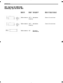
7 Zubehör
7.1 XHT Lötspitzen für den Lötkolben WXP 200
Siehe Tabelle XHT Lötspitzen für Lötkolben WXP 200 am Ende
dieser Anleitung und auf www.weller.eu
7.2 Ersatzteile und Zubehör für WXP 200
Bestell-Nr. Beschreibung
T0052920599 WXP 200 Lötkolben
T0051515898 Sicherheitsablage WDH 31
T0051384199 Spiralwolle für Reinigungseinsatz für WDC 2
T0058741753 Einmaulschlüssel SW17
8 Entsorgung
Entsorgen Sie ausgetauschte Geräteteile, Filter oder alte Geräte
gemäß den Vorschriften Ihres Landes.
9 Garantie
Die Mängelansprüche des Käufers verjähren nach einem Jahr ab
Ablieferung an ihn. Dies gilt nicht für Rückgriffsansprüche des
Käufers nach §§ 478, 479 BGB.
Aus einer von uns abgegebenen Garantie haften wir nur bei
Ansprüchen, wenn die Beschaffenheits- oder Haltbarkeitsgarantie
von uns schriftlich und unter Verwendung des Begriffs „Garantie“
abgegeben worden ist.
Technische Änderungen vorbehalten!
Die aktualisierten Betriebsanleitungen finden Sie unter
www.weller.eu.

EN
FR IT ES PT NL SV DK FI GR TR CZ PL HU SK SL EE LV LT DE
WXP 200
Operating Instructions

WXP 200
WXP 200
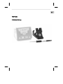
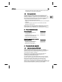
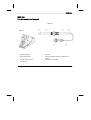
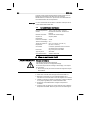
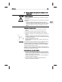
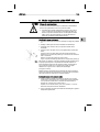
Hardware Overview
1. Cleaning element 5. Handle
2. Soldering tip 6. Heat-resistant antistatic silicon cable
3. Tip handle 7. Lockable connector plug
4. LED status indicato
r
WDH 31
WXP 200

WXP 200 3-8
DE EN FR IT ES PT NL SV DK FI GR TR CZ PL HU SK SL EE LV LT
Table of Contents
1About these instructions ............................................................ 3
2For your safety ........................................................................... 3
3Included in delivery .................................................................... 5
4Device description ..................................................................... 5
5Commissioning the device ......................................................... 6
6Replacing the WXP 200 soldering tips ...................................... 6
7Accessories ............................................................................... 7
8Disposal ..................................................................................... 7
9Warranty .................................................................................... 8
1 About these instructions
Thank you for the confidence you have shown in buying the Weller
WXP 200 soldering iron. The device has been manufactured in
accordance with the most rigorous quality standards, which ensure
that it operates perfectly.
These instructions contain important information which will help you
to start up, operate and service the WXP 200 soldering iron safely
and correctly as well as to eliminate simple faults or malfunctions
yourselves.
Z Read these instructions and the accompanying safety information
carefully before starting up the device and starting work with the
WXP 200 soldering iron.
Z Keep these instructions in a safe place and so that they are
easily accessible to all users.
1.1 Directives taken into consideration
The Weller WXP 200 soldering iron conforms to the specifications of
the EC Declaration of Conformity as defined by Directives
2004/108/EC and 2006/95/EC.
1.2 Applicable documents
− Operating instructions for your supply unit
− Operating instructions for WXP 200
− Safety information booklet accompanying these instructions
2 For your safety
− The WXP 200 soldering iron has been manufactured in
accordance with the current state of the art and recognised safety
rules and regulations. There is nevertheless the risk of personal
injury and damage to property if you fail to observe the safety
information set out in the accompanying booklet and the warnings
given in these instructions.

4-8 WXP 200
− Always pass on the WXP 200 soldering iron to third parties
together with these operating instructions.
− The manufacturer accepts no liability for improper use of the tool
or for unauthorised modifications.
2.1 Please observe the following guidelines:
General
information
− Always place the WXP 200 soldering iron in the intended safety
rest.
− Remove all inflammable articles from around the hot soldering
iron.
− Always wear suitable protective clothing when using the
WXP 200.
− Never leave a hot WXP 200 unattended.
− Do not work on electrically live parts.
− Antistatic plastics are provided with conductive fillers to prevent
the build-up of static charge. This also reduces the insulating
properties of the plastic.
Do not work on electrically live parts.
− Always wear eye protection when working with soldering and
desoldering applications.
− Read and follow the operating instructions for the Weller WX
supply unit.
Handling
soldering/
desoldering
tips
− Do not place or leave hot soldering/desoldering tips on the
worktop or on plastic surfaces.
− Wet the tinned soldering/desoldering tips with solder once they
have heated up in order to remove oxide layers that form during
storage or contamination from the soldering/desoldering tips.
− Ensure the soldering/desoldering tips are well wetted during
intervals between soldering and desoldering and prior to storage
of the device.
− Do not use aggressive fluxing agents.
− Always make sure that the soldering/desoldering tips are
properly seated.
− Select the lowest possible working temperature.
− Select the largest possible soldering/desoldering tip shape for
the application (roughly as large as the soldering pad).
− Wet the soldering/desoldering tips well to ensure efficient heat
transfer between the soldering/desoldering tips and the soldering
spot.
− Switch off the system if you do not intend to use the
soldering/desoldering tool for prolonged periods.
− Wet the tips before placing the soldering/desoldering tool in the
safety rest.
− Apply the solder directly at the soldering point, not on the
soldering/desoldering tips.
− Do not apply excessive force to the soldering/desoldering tips.
−
A
lways make sure that the soldering iron is placed properly in the
safety rest.

WXP 200 5-8
DE EN FR IT ES PT NL SV DK FI GR TR CZ PL HU SK SL EE LV LT
2.2 Intended use
Use the WXP 200 soldering iron exclusively for the purpose
indicated in the operating instructions of releasing, accommodating
and depositing electronic components under the conditions specified
herein. Intended use of the WXP 200 soldering iron also includes the
requirement that you
− adhere to these instructions,
− observe all other accompanying documents,
− comply with national accident prevention guidelines applicable at
the place of use.
The manufacturer accepts no liability for any damage resulting from
failure to use the device in compliance with these operating
instructions or unauthorised modifications to the device.
3 Included in delivery
WXP 200 (packed) T0052920599:
− Soldering iron WXP 200, T0052920599
− 17 mm open end wrench T0058741753
− XHT D chisel 5 X 1.2 mm T0054480199
− Operating instructions of WXP 200
− Safety information booklet
Also included in WXP 200 soldering set T0052920699:
− WDH 31 safety rest T0051515898
− Sole plate connector T0058703153
− Operating instructions of WDC 2
4 Device description
4.1 Soldering iron WXP 200
The WXP 200 soldering iron is characterised by fast and precise
achievement of the soldering tip temperature. A highly powerful
200 W heater element provides excellent dynamic performance.
With its additional optimised sensor position, this soldering iron is
ideal for soldering applications requiring high heat.
Thanks to its slim-line design and the extremely short distance from
the handle to the tip, this soldering iron can be used for general
purposes from precision soldering to high-temperature soldering.
The WXP 200 is equipped with a usage detector and can be
automatically switched to standby mode or switched off when not in
use. The operating status is indicated by the status indicator LED.
For directions for setting the standby temperature and the switching
times, please refer to the operating instructions of the WX supply
unit in use.
Note The WXP 200 soldering iron by Weller may only be operated
together with Weller WX supply units.

6-8 WXP 200
4.2 Technical data
Temperature range 100°C - 450°C (212°F - 850°F)
Tool cable Silicone rubber, heat resistant
Heating element Integrated heating wire element
Temperature senso
r
Platinum senso
r
Heating output 200 W
Voltage (heater) 24 V
Heat-up time (approx.) 19s (50°C to 380°C)
(120°F to 660°F)
Connection 6 pin connector, polarity protected with lock
Weight 94 g incl. cordless tip
Tip type
Supply unit
XHT series
Weller WX stations
5 Commissioning the device
WARNING!
Risk of burns
The soldering tips of soldering irons become very hot during
soldering and desoldering processes.
There is a risk of burns from touching the tips.
Z Do not touch the hot soldering tips and keep them away from
inflammable objects.
1. Carefully unpack the WXP 200 soldering iron.
2. Place the soldering iron into safety rest WDH 31.
3. Insert the connecting plug (7) into the power supply socket and
lock it by turning it clockwise.
4. Check to make sure that the mains voltage matches the voltage
specified on the rating plate of the WX supply unit.
5. Switch on the supply unit and set the required temperature.
6. If the tool has not reached the required temperature, the status
indicator LED (4) will be lit continuously. Wet the soldering tip
with solder.
6 Replacing the WXP 200 soldering tips
WARNING!
Risk of burns
The soldering tip becomes hot during soldering and desoldering
processes.
There is a risk of burns from touching the soldering tip.
Z The soldering tool must be switched off and stand at least
3 min. in the safety rest (WDH 31) until the soldering tip has
cooled off. The status indicator LED (4) must be OFF. Only
replace the soldering tips when they are cold.

WXP 200 7-8
DE EN FR IT ES PT NL SV DK FI GR TR CZ PL HU SK SL EE LV LT
Replacing a used tip
1. Place the soldering tool in the WDH 31 safety rest.
2. Switch off the power switch of the supply unit.
3. Wait five minutes until the soldering tip has cooled down.
4. Hold the soldering iron with the tip facing slightly downwards.
Hold the soldering iron by the rear handle (5) and unscrew the tip
receptacle (3) using the supplied 17 mm open end wrench
Pull off the soldering tip (2) forwards
The soldering tip is now resting loosely in the tip receptacle (3)
Note Do not place or leave the hot soldering tip or probe tip on the
cleaning sponge or on plastic surfaces. When using multiple types
of soldering tip, it is recommended that the soldering tip (2) and tip
receptacle (3) be used together in the changing system (see figure
above).
Keep the heat transfer surfaces of the soldering tip and heating
element clean. The heating element must not come into contact with
soldering tin.
Inserting a new soldering tip
5. Place the soldering tip into the tip receptacle with the tip facing
forwards. Push the tip receptacle together with the soldering tip
over the heating element and screw the soldering tip securely
into place using a 17 mm open end wrench.
Tighten to a low torque, as otherwise you might damage the
tapered part of the heating element.
6. Switch on the power switch of the supply unit and set the
temperature to the required level.
7 Accessories
7.1 XHT soldering tips for the WXP 200 soldering
iron
See the table XHT soldering tips for WXP 200 soldering iron in the
section in the back and at www.weller.eu
7.2 Replacement parts and accessories for
WXP 200
Order no. Description
T0052920599 WXP 200 soldering iron
T0051515898 WDH 31 safety rest
T0051384199 Metal wool for cleaning element for WDC 2
T0058741753 17 mm open end wrench
8 Disposal
Dispose of replaced equipment parts, filters or old devices in
accordance with the rules and regulations applicable in your country.

8-8 WXP 200
9 Warranty
Claims by the buyer for physical defects are time-barred after a
period of one year from delivery to the buyer. This does not apply to
claims by the buyer for indemnification in accordance with §§ 478,
479 BGB (German Federal Law Gazette).
We shall only be liable for claims arising from a warranty furnished
by us if the quality or durability warranty has been furnished by use
in writing and using the term "Warranty“.
In addition, for the USA and Canada:
Cooper Tools warrants to the original purchaser and any subsequent
owner (“Buyer”) that Weller soldering and desoldering products will
be free from defects in material and workmanship for a period of one
year from date of purchase, provided that no warranty is made with
respect to products which have been altered, subjected to abuse or
improperly used, installed or repaired. Use of non-Cooper Tools
components will void this warranty if a non-Cooper Tools component
is defective (or is the source of the defect). Cooper Tools will repair
or replace products found to be defective not caused by a part,
component or accessory manufactured by another company, during
the warranty period. Contact Cooper Tools with dated proof of
purchase and return to Apex Tool Group, LLC., 14600 York Rd. Suit
A, Sparks, MD 21152. All costs of transportation and reinstallation
shall be borne by the Buyer.
IN NO EVENT SHALL COOPER TOOLS BE LIABLE FOR
INCIDENTAL OR CONSEQUENTIAL DAMAGES. COOPER TOOLS
LIABILITY FOR ANY CLAIMS ARISING OUT OF THIS WARRANTY
SHALL NOT EXCEED THE PURCHASE PRICE OF THE
PRODUCT.
THE PERIOD OF ALL IMPLIED WARRANTIES APPLICABLE TO
THIS PRODUCT INCLUDING ANY IMPLIED WARRANTY OF
MERCHANTABILITY OR FITNESS, OR FITNESS FOR A
PARTICULAR PURPOSE IS LIMITED TO 12 MONTHS FROM THE
DATE OF PURCHASE BY THE USER.
Some states do not allow the exclusion or limitation of incidental or
consequential damages, so the above limitation or exclusion may
not apply to you. Some states do not allow limitation on how long an
implied warranty lasts, so the above limitation may not apply to you.
This warranty gives you specific legal rights, and you may also have
other rights, which vary from state to state.
Subject to technical alterations and amendments!
Updated operating instructions are available for download at
www.weller.eu.
La pagina sta caricando ...
La pagina sta caricando ...
La pagina sta caricando ...
La pagina sta caricando ...
La pagina sta caricando ...
La pagina sta caricando ...
La pagina sta caricando ...
La pagina sta caricando ...
La pagina sta caricando ...
La pagina sta caricando ...
La pagina sta caricando ...
La pagina sta caricando ...
La pagina sta caricando ...
La pagina sta caricando ...
La pagina sta caricando ...
La pagina sta caricando ...
La pagina sta caricando ...
La pagina sta caricando ...
La pagina sta caricando ...
La pagina sta caricando ...
La pagina sta caricando ...
La pagina sta caricando ...
La pagina sta caricando ...
La pagina sta caricando ...
La pagina sta caricando ...
La pagina sta caricando ...
La pagina sta caricando ...
La pagina sta caricando ...
La pagina sta caricando ...
La pagina sta caricando ...
La pagina sta caricando ...
La pagina sta caricando ...
La pagina sta caricando ...
La pagina sta caricando ...
La pagina sta caricando ...
-
 1
1
-
 2
2
-
 3
3
-
 4
4
-
 5
5
-
 6
6
-
 7
7
-
 8
8
-
 9
9
-
 10
10
-
 11
11
-
 12
12
-
 13
13
-
 14
14
-
 15
15
-
 16
16
-
 17
17
-
 18
18
-
 19
19
-
 20
20
-
 21
21
-
 22
22
-
 23
23
-
 24
24
-
 25
25
-
 26
26
-
 27
27
-
 28
28
-
 29
29
-
 30
30
-
 31
31
-
 32
32
-
 33
33
-
 34
34
-
 35
35
-
 36
36
-
 37
37
-
 38
38
-
 39
39
-
 40
40
-
 41
41
-
 42
42
-
 43
43
-
 44
44
-
 45
45
-
 46
46
-
 47
47
-
 48
48
-
 49
49
-
 50
50
-
 51
51
-
 52
52
-
 53
53
-
 54
54
-
 55
55


Weller C-WXP200 Manuale del proprietario
- Categoria
- Saldatori
- Tipo
- Manuale del proprietario
in altre lingue
- français: Weller C-WXP200 Le manuel du propriétaire
- español: Weller C-WXP200 El manual del propietario
- Deutsch: Weller C-WXP200 Bedienungsanleitung
- português: Weller C-WXP200 Manual do proprietário
Documenti correlati
-
Weller WXP 120 Operating Instructions Manual
-
-
Weller WXP 120 Set Istruzioni per l'uso
-
Weller WX2 Operating Instructions Manual
-
Weller WXR 3 Translation Of The Original Instructions
-
-
Weller WXMT Operating Instructions Manual
-
-
Weller WMRP Operating Instructions Manual
-
Weller WP 200 Operating Instructions Manual