Dometic MagicWatch MWE4004 Guida d'installazione
- Tipo
- Guida d'installazione

1
––
a < 60 cm
a > 60 cm 24 mm
24 mm
–
–
12°
a
12°
a
C
A
B
Click!
3421
a
a
a
50 cm
25 cm
50 cm
25 cm
20 cm 20 cm35 cm 35 cm
50 cm25 cm 50 cm50 cm
24 mm
a = max. 100 cm!
1
1
2
3 4
2
3
4
1 2
3
4
1
2
3
4
5
6
8
7
2.5 m
4.5 m
7.0 m
9.0 m
1x
1x
1x
1x
4x4x
4x
1x 1x
1x
1x
20x
MWE4004
EN: 7
DE: 20
FR: 34
ES: 48
PT: 61
IT: 75
NL: 88
DA: 101
SV: 113
NO: 126
FI: 139
RU: 153
PL: 167
SK: 180
CS: 193
HU: 206
EN: 7
DE: 20
FR: 34
ES: 48
PT: 61
IT: 75
NL: 88
DA: 101
SV: 114
NO: 127
FI: 140
RU: 154
PL: 168
SK: 181
CS: 194
HU: 207
EN: 5
DE: 18
FR: 32
ES: 46
PT: 59
IT: 73
NL: 86
DA: 99
SV: 112
NO: 125
FI: 138
RU: 152
PL: 166
SK: 179
CS: 192
HU: 205
EN: 6
DE: 19
FR: 33
ES: 47
PT: 60
IT: 74
NL: 87
DA: 100
SV: 113
NO: 126
FI: 139
RU: 153
PL: 167
SK: 180
CS: 167
HU: 206
1
3
4
2
5
7
6
leaflet_figures.fm Seite 1 Freitag, 7. September 2018 8:56 08

2
Dometic WAECO International GmbH
Hollefeldstrasse 63
D-48282 Emsdetten
www.dometic.com
(bl) (rt)
3 (STOP)
(or)
2
(gn)
1
SENS
1 2 3 4
VOL
21
br
rt/gr
rt
ge/sw
ge
bl
5
6
11
4
10
31
13
2
7
8
9
3
sw
sw
sw
sw
sw
ge/bl
+12/24V +12/24V
ws
sw
ws
bl/sw
ws/bl
12
n. c.
rt
0
240
120
000000
2914156734 8 10
SENS
1 2 3 4
VOL
1
P
1
2
321
~ 80 cm
~ 65 cm
~ 50 cm
SENS
1 2 3 4
VOL
1
23
4
1.
2.
12 mm
A
1.
2.
B
EN: 9
DE: 22
FR: 37
ES: 50
PT: 64
IT: 77
NL: 90
DA: 103
SV: 116
NO: 129
FI: 142
RU: 157
PL: 170
SK: 183
CS: 196
HU: 209
EN: 8
DE: 21
FR: 35
ES: 49
PT: 62
IT: 76
NL: 89
DA: 102
SV: 115
NO: 128
FI: 141
RU: 155
PL: 169
SK: 182
CS: 195
HU: 208
EN: 10
DE: 23
FR: 37
ES: 51
PT: 64
IT: 78
NL: 91
DA: 104
SV: 117
NO: 130
FI: 143
RU: 157
PL: 171
SK: 184
CS: 197
HU: 210
EN DE FR ES PT IT NL DA
bl Blue Blau Bleu Azul Azul Blu Blauw Blå
br Brown Braun Marron Marrón Castanho Marrone Bruin Brun
ge Yellow Gelb Jaune Amarillo Amarelo Giallo Geel Gul
gr Grey Grau Gris Gris Cinzento Grigio Grijs Grå
or
Orange Orange Orange Naranja Cor de
laranja
Arancione Oranje Orange
rt Red Rot Rouge Rojo Vermelho Rosso Rood Rød
sw Black Schwarz Noir Negro Preto Nero Zwart Sort
SV NO FI RU PL SK CS HU
bl Blå Blå Sininen Синий Niebieski Modrá Modrá Kék
br Brun Brun Ruskea Коричневый Brązowy Hnedá Hněda Barna
ge Gul Gul Keltainen Желтый Żółty Žltá Žlutá Sárga
gr Grå Grå Harmaa Серый Szary Sivá Šedá Szürke
or Orange Oransje Oranssi Оранжевый Pomarańczowy Oranžová Oranžová Narancs
rt Röd Rød Punainen Красный Czerwony Červená Červená Piros
sw Svart Svart Musta Черный Czarny Čierna Černá Fekete
9
b8
a
0
c
d
4445101737 08/2018
leaflet_figures.fm Seite 2 Freitag, 7. September 2018 8:56 08

MWE4004
Blind spot assistant
Installation and Operating Manual. . . . . . . . 3
Toter-Winkel-Assistent
Montage- und Bedienungsanleitung . . . . . 16
Assistant d'angle mort
Instructions de montage
et de service . . . . . . . . . . . . . . . . . . . . . . . . .30
Asistente de ángulo muerto
Instrucciones de montaje y de uso . . . . . . .44
Assistente para ângulos mortos
Instruções de montagem e manual de
instruções . . . . . . . . . . . . . . . . . . . . . . . . . . .57
Assistente punto morto
Istruzioni di montaggio e d’uso . . . . . . . . . 71
Dodehoekassistent
Montagehandleiding en
gebruiksaanwijzing . . . . . . . . . . . . . . . . . . .84
Dødvinkelassistent
Monterings- og betjeningsvejledning. . . . 97
Dödvinkelassistent
Monterings- och bruksanvisning . . . . . . . 110
Dødvinkelassistent
Monterings- og bruksanvisning . . . . . . . . 123
Kuollut kulma -assistentti
Asennus- ja käyttöohje . . . . . . . . . . . . . . . 136
Детектор мертвых зон
Инструкция по монтажу и эксплуатации 149
Asystent martwego pola
Instrukcja montażu i obsługi. . . . . . . . . . . 164
Asistent mŕtveho uhla
Návod na montáž a uvedenie
do prevádzky. . . . . . . . . . . . . . . . . . . . . . . 177
Asistent hlídání mrtvého úhlu
Návod k montáži a obsluze . . . . . . . . . . . 190
Holttér-asszisztens
Szerelési és használati útmutató . . . . . . . 203
EN
DE
FR
ES
PT
IT
NL
DA
SV
NO
FI
RU
PL
SK
CS
HU
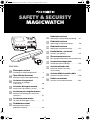
SAFETY & SECURITY
MAGICWATCH
MWE4004-IO-16s.book Seite 1 Freitag, 7. September 2018 8:57 08

MWE4004-IO-16s.book Seite 2 Freitag, 7. September 2018 8:57 08

EN
MWE4004
3
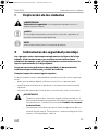
Please read this instruction manual carefully before installation and first
use, and store it in a safe place. If you pass on the product to another
person, hand over this instruction manual along with it.
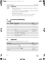
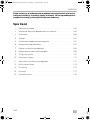
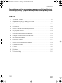
Table of contents
1 Explanation of symbols. . . . . . . . . . . . . . . . . . . . . . . . . . . . . . . . . . . . . . . . . . .4
2 Safety and installation instructions . . . . . . . . . . . . . . . . . . . . . . . . . . . . . . . . . .4
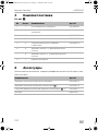
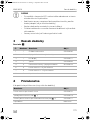
3 Scope of delivery . . . . . . . . . . . . . . . . . . . . . . . . . . . . . . . . . . . . . . . . . . . . . . .5
4 Accessories . . . . . . . . . . . . . . . . . . . . . . . . . . . . . . . . . . . . . . . . . . . . . . . . . . . .6
5 Intended use . . . . . . . . . . . . . . . . . . . . . . . . . . . . . . . . . . . . . . . . . . . . . . . . . . .6
6 Instructions before installation . . . . . . . . . . . . . . . . . . . . . . . . . . . . . . . . . . . . .6
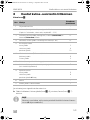
7 Installing the blind spot aid. . . . . . . . . . . . . . . . . . . . . . . . . . . . . . . . . . . . . . . .7
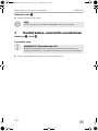
8 Connecting the blind spot assistant. . . . . . . . . . . . . . . . . . . . . . . . . . . . . . . . .8
9 Detection range . . . . . . . . . . . . . . . . . . . . . . . . . . . . . . . . . . . . . . . . . . . . . . . .9
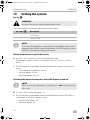
10 Setting the system. . . . . . . . . . . . . . . . . . . . . . . . . . . . . . . . . . . . . . . . . . . . . .10
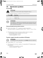
11 Using the blind spot assistant. . . . . . . . . . . . . . . . . . . . . . . . . . . . . . . . . . . . . 11
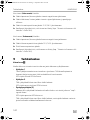
12 Troubleshooting . . . . . . . . . . . . . . . . . . . . . . . . . . . . . . . . . . . . . . . . . . . . . . .13
13 Warranty . . . . . . . . . . . . . . . . . . . . . . . . . . . . . . . . . . . . . . . . . . . . . . . . . . . . .14
14 Disposal. . . . . . . . . . . . . . . . . . . . . . . . . . . . . . . . . . . . . . . . . . . . . . . . . . . . . .14
15 Technical data . . . . . . . . . . . . . . . . . . . . . . . . . . . . . . . . . . . . . . . . . . . . . . . . .15
MWE4004-IO-16s.book Seite 3 Freitag, 7. September 2018 8:57 08

EN
Explanation of symbols MWE4004
4
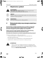
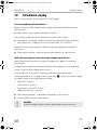
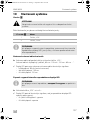
1 Explanation of symbols
!
A
I
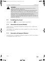
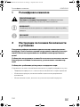
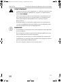
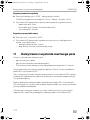
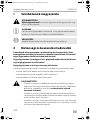
2 Safety and installation instructions
The following texts are only a supplement to the illustrations on the
supplementary sheet. They do not contain the full installation and
operating instructions. Please observe the illustrations on the
supplementary sheet.
Please observe the prescribed safety instructions and stipulations from the
vehicle manufacturer and service workshops.
Observe the applicable legal regulations.
The manufacturer accepts no liability for damage in the following cases:
•
Damage to the product resulting from mechanical influences and excess voltage
•
Alterations to the product without express permission from the manufacturer
•
Use for purposes other than those described in the operating manual
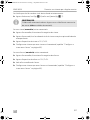
!
WARNING!
•
Secure the parts of the blind spot assistant which are installed in the
vehicle in such a way that they cannot become loose under any cir-
cumstances (sudden braking, accidents) and cause injuries to the
occupants of the vehicle.
•
Do not install the parts of the blind spot assistant anywhere in the vehi-
cle where an airbag may open. This could cause injury if the airbag
deploys.
WARNING!
Safety instruction: Failure to observe this instruction can cause fatal or
serious injury.
NOTICE!
Failure to observe this instruction can cause material damage and impair
the function of the product.
NOTE
Supplementary information for operating the product.
MWE4004-IO-16s.book Seite 4 Freitag, 7. September 2018 8:57 08

EN
MWE4004 Scope of delivery
5
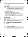
•
The blind spot assistant is intended as an additional aid, which means
it does not relieve you of the obligation to take due care when
manoeuvring.
A
NOTICE!
•
Installing the blind spot assistant can cause problems on vehicles with
LED tail lights.
•
If you would like to install the sensors on metal bumpers, you will
require suitable adapters (not included in the scope of delivery).
•
Do not expose the control electronics to dampness.
•
Do not install the control electronics near any other control modules.
•
The sensors may not cover signal lamps.
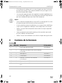
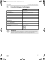
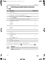
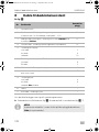
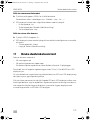
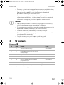
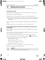
3Scope of delivery
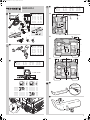
See fig. 1
No. Quantity Description Ref. no.
1 1 Control electronics 9101500080
2 1 Control electronics connection cable
3 1 LED display 9101500077
4 1 Switch 9101500066
5 4 Ultrasonic sensors with connection cable 9101500076
6 4 0° sensor holder with cover ring
7 4 12° sensor holder with cover ring
8 1 Fastening material
MWE4004-IO-16s.book Seite 5 Freitag, 7. September 2018 8:57 08

EN
Accessories MWE4004
6
4Accessories
Available as accessories (not included in the scope of delivery):
5 Intended use
Dometic MWE4004 (ref. no. 9600000358) is a blind spot assistant based on ultra-
sound. When manoeuvring, it monitors the space around the vehicle and provides
an audible and visible warning signal for any obstacles it detects.
MWE4004 is designed for installation in commercial vehicles.
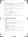
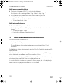
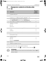
6 Instructions before installation
6.1 Painting the sensors
See fig. 2
I
Description Ref. no.
Sensor holder for metal bumper 9101500015
Subframe sensor holder (fig. d 1) 9101500078
Rubber sensor holder for surface mounting (fig. d 2) 9101500071
Loudspeaker MWD-900
NOTE
The sensors may be painted. The manufacturer recommends having the
sensors painted by a specialist workshop.
MWE4004-IO-16s.book Seite 6 Freitag, 7. September 2018 8:57 08

EN
MWE4004 Installing the blind spot aid
7
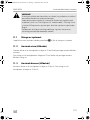
6.2 Determining the place of installation for the sensors
See fig. 3 to fig. 5
I
Note the following during installation:
•
The area around the sensors must be free from other objects.
•
The distance from the sensors to the ground when horizontally aligned should be
at least 45 cm and a maximum of 60 cm (fig. 3).
•
Note that the installation angle depends on the installation height.
Select the right sensor holder and the appropriate drill diameter by consulting
the table in fig. 3.
Supplementary to fig. 5
➤ Observe the intervals between sensors.
I
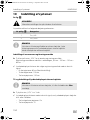
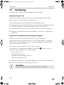
7 Installing the blind spot aid
See fig. 6 to fig. 0
Supplementary to fig.
?
A
➤ Push the sensor holders into the holes until they lock into place.
NOTE
The sensors must be correctly aligned for the device to work properly.
If they point to the ground, irregularities and bumps on the surface may
be interpreted as obstacles. If they point too far up, obstacles will not be
detected at all.
NOTE
You can also distribute the sensors as shown in alternative B and C.
NOTICE! Risk of malfunction!
Align the sensor holders so that the fastening lugs are horizontal. Other-
wise there is no guarantee the blind spot assistant will function correctly.
MWE4004-IO-16s.book Seite 7 Freitag, 7. September 2018 8:57 08

EN
Connecting the blind spot assistant MWE4004
8
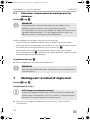
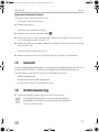
8 Connecting the blind spot assistant
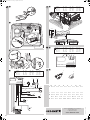
See fig. a
If a signal is not emitted from the parking brake:
➤ Connect the white/blue cable (fig. a 4) with the blue/black cable (fig. a 7).
I
No. Description
Plug socket
for plug
1 Control electronics –
2 Yellow/black cable: Connection to the cruise control
(4 pulses every 1 m, square wave, amplitude 5 – 32 V)
14
3 Red/grey cable (earth signal): Connection to a siren (accessory)
or a camera (accessory)
13
4 White/blue cable: Connection to parking brake (see below) 12
5 Connection to LED display:
Black cable
White cable
Red cable
3
4
10
6 Connection to external loudspeaker (accessory)
Yellow cable
Blue cable
9
2
7 Blue/black cable: Connection to ignition 8
8 Yellow/blue cable: Connection to passenger indicator (when
using siren only)
7
9 Connection switch:
Black cable
White cable
Red cable not connected
5
6
—
10 Sensors –
11 Brown cable: Connection to earth 1
NOTE
The manufacturer recommends applying some grease to the sensor
plug connections (not on the control module).
MWE4004-IO-16s.book Seite 8 Freitag, 7. September 2018 8:57 08

EN
MWE4004 Detection range
9
If a siren (accessory) is connected:
➤ Connect the red/grey cable with the negative cable of the siren.
➤ Connect the yellow/blue cable with the signal cable of the siren and the
passenger indicator.
➤ Connect the positive cable of the siren with 12 V/24 V.
➤ Configure the system so that a siren is connected (chapter “Setting the siren or
camera” on page 11).
If a camera (accessory) is connected:
➤ Connect the red/grey cable with the negative cable of the camera.
➤ Connect the positive cable of the camera with 12 V/24 V.
➤ Insulate the red cable of the camera.
➤ Configure the system so that a camera is connected (chapter “Setting the siren or
camera” on page 11).
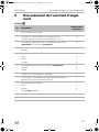
9Detection range
See fig. b
The detection range of the blind spot assistant is divided into three zones:
•
Zone 1
This zone is the first limit range. Small objects or those with poor reflective
characteristics may not be detected here.
The green LEDs light up in the LED display.
•
Zone 2
Nearly all objects in this zone are displayed.
The orange LEDs light up in the LED display.
•
Stop zone (3)
If there are objects in this zone, the blind spot assistant emits a continuous tone
warning you to stop.
The red LEDs light up in the LED display.
Virtually all objects are displayed in this zone, but some objects may end up in
the blind spot of the sensors.
MWE4004-IO-16s.book Seite 9 Freitag, 7. September 2018 8:57 08

EN
Setting the system MWE4004
10
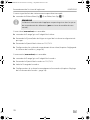
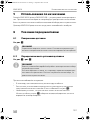
10 Setting the system
See fig. c
!
The control electronics have the following control elements:
I
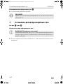
Setting the detection range of the sensors
➤ Press the “VOL” briefly to switch to the detection range.
The detection ranges switches in the order of “80 cm – 100 cm – 120 cm –
80 cm …”.
✓ The LED display acknowledges the selected detection range with an acoustic
signal:
– a short beep: 80 cm (default setting)
– two short beeps: 100 cm
– three short beeps: 120 cm
Switching the internal loudspeaker of the LED display on and off
I
➤ Press the “VOL” button for approx. 3 s.
✓ The LED display acknowledges whether the loudspeaker of the LED display is
switched on or off with an acoustic signal:
– three fast short beeps: off
– three short beeps: on
WARNING!
Incorrect settings can impair the operational safety.
No. in fig. c Description
1 “VOL” button
2 “SENS” button
NOTE
If an external loudspeaker is connected and switched on, the acknowl-
edgement tones of the internal loudspeaker of the LED display are emit-
ted after a time delay on the external speaker.
NOTE
When an external loudspeaker is connected, it is not switched on and
off as well.
MWE4004-IO-16s.book Seite 10 Freitag, 7. September 2018 8:57 08

EN
MWE4004 Using the blind spot assistant
11
Setting the sensitivity of the sensors
➤ Press the “SENS” button briefly to switch to the sensitivity.
The sensitivity switches in the order “Low – Medium – High – Low …”.
✓ The LED display acknowledges the selected sensitivity with an acoustic signal:
– a short beep: low
– two short beeps: medium (default setting)
– three short beeps: High
Setting the siren or camera
➤ Press the “SENS” button for approx. 3 s.
✓ The LED display acknowledges whether you have configured a siren or a camera
with an acoustic signal:
– ten short beeps: Siren
– longer tone: Camera (default setting)
11 Using the blind spot assistant
The sensors are activated automatically:
•
when the ignition is turned on
•
when the parking brake is released
Here the parking brake must be connected on plug socket 12 of the plug.must
be connected to
They stay active as long as the speed stays under 15 km/h. The blue LED in the LED
display lights up.
As soon as there is an obstacle within the detection range, the LEDs in the
LED display light up and a repeated, even signal tone is emitted.
As you approach, the different coloured LEDs show up in the LED display which zone
the obstacle is in, thereby indicating approximately the how far away it is.
Be very careful the first time you use the system, until you are familiar with the various
sequences with the LEDs in the LED display.
MWE4004-IO-16s.book Seite 11 Freitag, 7. September 2018 8:57 08

EN
Using the blind spot assistant MWE4004
12
!
11.1 Switching off the system
The system can be switched off in an emergency with the switch (fig. 1 4).
11.2 Using the siren (accessory)
The siren is activated when the vehicle speed drops below 15 km/h and the
passenger indicator is activated.
It is switched off when the vehicle speed exceeds 15 km/h or when the passenger
indicator is deactivated.
11.3 Using the camera (accessory)
The camera is activated when the vehicle speed drops below 15 km/h. It is switched
off when the speed exceeds 15 km/h.
WARNING!
Stop the vehicle immediately and investigate the situation (getting out if
necessary), if the following happens while you are manoeuvring:
the device first indicates an obstacle and the tone sequence speeds up
normally (e.g. from slow to medium) when manoeuvring. the signal tone
suddenly slows down, or no obstacle is indicated at all.
This means that the original obstacle is in the blind spot of the sensors
(construction-related characteristic), and there is still a potential for
collision.
MWE4004-IO-16s.book Seite 12 Freitag, 7. September 2018 8:57 08

EN
MWE4004 Troubleshooting
13
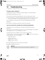
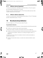
12 Troubleshooting
If a fault occurs, the blue LED flashes in the LED display.
The device shows no function.
The blue/black or brown cable for the voltage supply are not making contact.
➤ Check the connections are secure.
The white/blue cable for the parking brake is not receiving a positive signal.
➤ Check whether the white/blue cable for the deactivated parking brake has a pos-
itive signal (see chapter “Connecting the blind spot assistant” on page 8).
The system plug is not connected or not correctly plugged into the control
electronics.
➤ Check the system plugs and make sure they lock into place.
Low error tone for three seconds after switching on the ignition.
One or more sensors are defective or no longer connected to the control
electronics.
After the low tone, the loudspeaker emits the same number of beeps as the number
of the defective sensor, e. g. two beeps for sensor 2.
If more than one sensor is defective, they are shown in succession.
The LED display also indicates the defective sensor (fig. 5; sensor 1 has the shortest
connection cable , sensor 4 the longest):
•
Green LED: Sensor 1
•
Orange LED: Sensor 2
•
Middle red LED: Sensor 3
•
Middle red LED: Sensor 4
➤ Check the plugs and make sure they lock into place.
➤ Replace the defective sensor(s).
A
NOTICE!
The system does not work if one or more sensors are defective.
MWE4004-IO-16s.book Seite 13 Freitag, 7. September 2018 8:57 08

EN
Warranty MWE4004
14
Device indicates obstacles incorrectly
False alarms may have the following causes:
•
Dirt or frost on the sensors.
➤ Clean the sensors.
•
The sensors were incorrectly installed.
➤ Adjust the position of the sensors (fig. 3).
➤ If necessary, set the detection range of the sensors (see chapter “Setting the
detection range of the sensors” on page 10).
➤ If necessary, set the sensitivity of the sensors (chapter “Setting the sensitivity of
the sensors” on page 11).
•
The sensors are in contact with the chassis.
➤ Disconnect the sensors from the chassis and secure the sensor correctly in the
sensor holder.
13 Warranty
The statutory warranty period applies. If the product is defective, please contact the
manufacturer's branch in your country (see the back of the instruction manual for the
addresses) or your retailer.
For repair and guarantee processing, please send the following items:
•
Defect components
•
A copy of the receipt with purchasing date
•
A reason for the claim or description of the fault
14 Disposal
➤ Place the packaging material in the appropriate recycling waste bins wherever
possible.
M
If you wish to finally dispose of the product, ask your local recycling centre
or specialist dealer for details about how to do this in accordance with the
applicable disposal regulations.
MWE4004-IO-16s.book Seite 14 Freitag, 7. September 2018 8:57 08

EN
MWE4004 Technical data
15
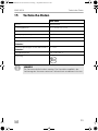
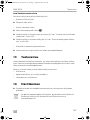
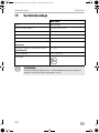
15 Technical data
I
MWE4004
Ref. no.: 9600000358
Detection range: approx. 0.15 m up to 1.20 m
Ultrasound frequency: 40 kHz
Input voltage: 10 – 32 V
Current: Max. 200 mA
Output current for sirens or camera
(accessory):
1A
Connection voltage for sirens or camera
(accessory):
12 – 24 V
Operating temperature: –25 °C to +85 °C
Certification:
NOTE
The sensors may be painted. The manufacturer recommends having the
sensors painted by a specialist workshop.
E8
MWE4004-IO-16s.book Seite 15 Freitag, 7. September 2018 8:57 08

DE
MWE4004
16
Bitte lesen Sie diese Anleitung vor Einbau und Inbetriebnahme sorgfältig
durch und bewahren Sie sie auf. Geben Sie sie im Falle einer Weitergabe
des Produktes an den Nutzer weiter.
Inhaltsverzeichnis
1 Erklärung der Symbole . . . . . . . . . . . . . . . . . . . . . . . . . . . . . . . . . . . . . . . . . .17
2 Sicherheits- und Einbauhinweise . . . . . . . . . . . . . . . . . . . . . . . . . . . . . . . . . .17
3 Lieferumfang . . . . . . . . . . . . . . . . . . . . . . . . . . . . . . . . . . . . . . . . . . . . . . . . . .18
4 Zubehör. . . . . . . . . . . . . . . . . . . . . . . . . . . . . . . . . . . . . . . . . . . . . . . . . . . . . .19
5 Bestimmungsgemäßer Gebrauch . . . . . . . . . . . . . . . . . . . . . . . . . . . . . . . . .19
6 Hinweise vor dem Einbau. . . . . . . . . . . . . . . . . . . . . . . . . . . . . . . . . . . . . . . .19
7 Toter-Winkel-Assistent montieren . . . . . . . . . . . . . . . . . . . . . . . . . . . . . . . . 20
8 Toter-Winkel-Assistent anschließen . . . . . . . . . . . . . . . . . . . . . . . . . . . . . . . .21
9 Erfassungsbereich. . . . . . . . . . . . . . . . . . . . . . . . . . . . . . . . . . . . . . . . . . . . . 22
10 System einstellen. . . . . . . . . . . . . . . . . . . . . . . . . . . . . . . . . . . . . . . . . . . . . . 23
11 Toter-Winkel-Assistent benutzen . . . . . . . . . . . . . . . . . . . . . . . . . . . . . . . . . 25
12 Fehler suchen . . . . . . . . . . . . . . . . . . . . . . . . . . . . . . . . . . . . . . . . . . . . . . . . 26
13 Gewährleistung. . . . . . . . . . . . . . . . . . . . . . . . . . . . . . . . . . . . . . . . . . . . . . . 28
14 Entsorgung . . . . . . . . . . . . . . . . . . . . . . . . . . . . . . . . . . . . . . . . . . . . . . . . . . 28
15 Technische Daten . . . . . . . . . . . . . . . . . . . . . . . . . . . . . . . . . . . . . . . . . . . . . 29
MWE4004-IO-16s.book Seite 16 Freitag, 7. September 2018 8:57 08

DE
MWE4004 Erklärung der Symbole
17
1 Erklärung der Symbole
!
A
I
2 Sicherheits- und Einbauhinweise
Die folgenden Texte ergänzen die Abbildungen auf dem Beiblatt lediglich.
Sie alleine sind keine vollständigen Einbau- und Bedienhinweise! Bitte
beachten Sie unbedingt die Abbildungen auf dem Beiblatt!
Beachten Sie die vom Fahrzeughersteller und vom Kfz-Handwerk vorge-
schriebenen Sicherheitshinweise und Auflagen!
Beachten Sie die geltenden gesetzlichen Vorschriften.
Der Hersteller übernimmt in folgenden Fällen keine Haftung für Schäden:
•
Beschädigungen am Produkt durch mechanische Einflüsse und falsche
Anschlussspannung
•
Veränderungen am Produkt ohne ausdrückliche Genehmigung vom Hersteller
•
Verwendung für andere als die in der Anleitung beschriebenen Zwecke
!
WARNUNG!
•
Befestigen Sie die im Fahrzeug montierten Teile des Toter-Winkel-
Assistenten so, dass sie sich unter keinen Umständen (scharfes
Abbremsen, Verkehrsunfall) lösen und zu Verletzungen der
Fahrzeuginsassen führen können.
•
Montieren Sie die im Fahrzeug montierten Teile des Toter-Winkel-
Assistenten nicht im Wirkungsbereich eines Airbags. Sonst besteht
Verletzungsgefahr, wenn der Airbag auslöst.
WARNUNG!
Sicherheitshinweis: Nichtbeachtung kann zu Tod oder schwerer
Verletzung führen.
ACHTUNG!
Nichtbeachtung kann zu Materialschäden führen und die Funktion des
Produktes beeinträchtigen.
HINWEIS
Ergänzende Informationen zur Bedienung des Produktes.
MWE4004-IO-16s.book Seite 17 Freitag, 7. September 2018 8:57 08

DE
Lieferumfang MWE4004
18
•
Der Toter-Winkel-Assistent soll Sie zusätzlich unterstützen, d. h. das
Gerät entbindet Sie nicht von Ihrer besonderen Vorsichtspflicht beim
Rangieren.
A
ACHTUNG!
•
Bei Fahrzeugen mit LED-Rücklichtern kann der Einbau des Toter-
Winkel-Assistenten zu Störungen führen.
•
Wenn Sie die Sensoren in Metall-Stoßfänger montieren möchten,
benötigen Sie geeignete Adapter (nicht im Lieferumfang enthalten).
•
Die Steuerelektronik darf keiner Feuchtigkeit ausgesetzt sein.
•
Die Steuerelektronik darf nicht in der Nähe von anderen Steuer-
modulen montiert werden.
•
Die Sensoren dürfen keine Signallampen verdecken.
3 Lieferumfang
Siehe Abb. 1
Nr. Menge Bezeichnung Art.-Nr.
1 1 Steuerelektronik 9101500080
2 1 Anschlusskabel Steuerelektronik
3 1 LED-Display 9101500077
4 1 Schalter 9101500066
5 4 Ultraschall-Sensoren mit Anschlusskabel 9101500076
6 4 Sensorhalter 0° mit Abdeckring
7 4 Sensorhalter 12° mit Abdeckring
8 1 Befestigungsmaterial
MWE4004-IO-16s.book Seite 18 Freitag, 7. September 2018 8:57 08
La pagina sta caricando ...
La pagina sta caricando ...
La pagina sta caricando ...
La pagina sta caricando ...
La pagina sta caricando ...
La pagina sta caricando ...
La pagina sta caricando ...
La pagina sta caricando ...
La pagina sta caricando ...
La pagina sta caricando ...
La pagina sta caricando ...
La pagina sta caricando ...
La pagina sta caricando ...
La pagina sta caricando ...
La pagina sta caricando ...
La pagina sta caricando ...
La pagina sta caricando ...
La pagina sta caricando ...
La pagina sta caricando ...
La pagina sta caricando ...
La pagina sta caricando ...
La pagina sta caricando ...
La pagina sta caricando ...
La pagina sta caricando ...
La pagina sta caricando ...
La pagina sta caricando ...
La pagina sta caricando ...
La pagina sta caricando ...
La pagina sta caricando ...
La pagina sta caricando ...
La pagina sta caricando ...
La pagina sta caricando ...
La pagina sta caricando ...
La pagina sta caricando ...
La pagina sta caricando ...
La pagina sta caricando ...
La pagina sta caricando ...
La pagina sta caricando ...
La pagina sta caricando ...
La pagina sta caricando ...
La pagina sta caricando ...
La pagina sta caricando ...
La pagina sta caricando ...
La pagina sta caricando ...
La pagina sta caricando ...
La pagina sta caricando ...
La pagina sta caricando ...
La pagina sta caricando ...
La pagina sta caricando ...
La pagina sta caricando ...
La pagina sta caricando ...
La pagina sta caricando ...
La pagina sta caricando ...
La pagina sta caricando ...
La pagina sta caricando ...
La pagina sta caricando ...
La pagina sta caricando ...
La pagina sta caricando ...
La pagina sta caricando ...
La pagina sta caricando ...
La pagina sta caricando ...
La pagina sta caricando ...
La pagina sta caricando ...
La pagina sta caricando ...
La pagina sta caricando ...
La pagina sta caricando ...
La pagina sta caricando ...
La pagina sta caricando ...
La pagina sta caricando ...
La pagina sta caricando ...
La pagina sta caricando ...
La pagina sta caricando ...
La pagina sta caricando ...
La pagina sta caricando ...
La pagina sta caricando ...
La pagina sta caricando ...
La pagina sta caricando ...
La pagina sta caricando ...
La pagina sta caricando ...
La pagina sta caricando ...
La pagina sta caricando ...
La pagina sta caricando ...
La pagina sta caricando ...
La pagina sta caricando ...
La pagina sta caricando ...
La pagina sta caricando ...
La pagina sta caricando ...
La pagina sta caricando ...
La pagina sta caricando ...
La pagina sta caricando ...
La pagina sta caricando ...
La pagina sta caricando ...
La pagina sta caricando ...
La pagina sta caricando ...
La pagina sta caricando ...
La pagina sta caricando ...
La pagina sta caricando ...
La pagina sta caricando ...
La pagina sta caricando ...
La pagina sta caricando ...
La pagina sta caricando ...
La pagina sta caricando ...
La pagina sta caricando ...
La pagina sta caricando ...
La pagina sta caricando ...
La pagina sta caricando ...
La pagina sta caricando ...
La pagina sta caricando ...
La pagina sta caricando ...
La pagina sta caricando ...
La pagina sta caricando ...
La pagina sta caricando ...
La pagina sta caricando ...
La pagina sta caricando ...
La pagina sta caricando ...
La pagina sta caricando ...
La pagina sta caricando ...
La pagina sta caricando ...
La pagina sta caricando ...
La pagina sta caricando ...
La pagina sta caricando ...
La pagina sta caricando ...
La pagina sta caricando ...
La pagina sta caricando ...
La pagina sta caricando ...
La pagina sta caricando ...
La pagina sta caricando ...
La pagina sta caricando ...
La pagina sta caricando ...
La pagina sta caricando ...
La pagina sta caricando ...
La pagina sta caricando ...
La pagina sta caricando ...
La pagina sta caricando ...
La pagina sta caricando ...
La pagina sta caricando ...
La pagina sta caricando ...
La pagina sta caricando ...
La pagina sta caricando ...
La pagina sta caricando ...
La pagina sta caricando ...
La pagina sta caricando ...
La pagina sta caricando ...
La pagina sta caricando ...
La pagina sta caricando ...
La pagina sta caricando ...
La pagina sta caricando ...
La pagina sta caricando ...
La pagina sta caricando ...
La pagina sta caricando ...
La pagina sta caricando ...
La pagina sta caricando ...
La pagina sta caricando ...
La pagina sta caricando ...
La pagina sta caricando ...
La pagina sta caricando ...
La pagina sta caricando ...
La pagina sta caricando ...
La pagina sta caricando ...
La pagina sta caricando ...
La pagina sta caricando ...
La pagina sta caricando ...
La pagina sta caricando ...
La pagina sta caricando ...
La pagina sta caricando ...
La pagina sta caricando ...
La pagina sta caricando ...
La pagina sta caricando ...
La pagina sta caricando ...
La pagina sta caricando ...
La pagina sta caricando ...
La pagina sta caricando ...
La pagina sta caricando ...
La pagina sta caricando ...
La pagina sta caricando ...
La pagina sta caricando ...
La pagina sta caricando ...
La pagina sta caricando ...
La pagina sta caricando ...
La pagina sta caricando ...
La pagina sta caricando ...
La pagina sta caricando ...
La pagina sta caricando ...
La pagina sta caricando ...
La pagina sta caricando ...
La pagina sta caricando ...
La pagina sta caricando ...
La pagina sta caricando ...
La pagina sta caricando ...
La pagina sta caricando ...
La pagina sta caricando ...
La pagina sta caricando ...
La pagina sta caricando ...
La pagina sta caricando ...
La pagina sta caricando ...
La pagina sta caricando ...
La pagina sta caricando ...
La pagina sta caricando ...
-
 1
1
-
 2
2
-
 3
3
-
 4
4
-
 5
5
-
 6
6
-
 7
7
-
 8
8
-
 9
9
-
 10
10
-
 11
11
-
 12
12
-
 13
13
-
 14
14
-
 15
15
-
 16
16
-
 17
17
-
 18
18
-
 19
19
-
 20
20
-
 21
21
-
 22
22
-
 23
23
-
 24
24
-
 25
25
-
 26
26
-
 27
27
-
 28
28
-
 29
29
-
 30
30
-
 31
31
-
 32
32
-
 33
33
-
 34
34
-
 35
35
-
 36
36
-
 37
37
-
 38
38
-
 39
39
-
 40
40
-
 41
41
-
 42
42
-
 43
43
-
 44
44
-
 45
45
-
 46
46
-
 47
47
-
 48
48
-
 49
49
-
 50
50
-
 51
51
-
 52
52
-
 53
53
-
 54
54
-
 55
55
-
 56
56
-
 57
57
-
 58
58
-
 59
59
-
 60
60
-
 61
61
-
 62
62
-
 63
63
-
 64
64
-
 65
65
-
 66
66
-
 67
67
-
 68
68
-
 69
69
-
 70
70
-
 71
71
-
 72
72
-
 73
73
-
 74
74
-
 75
75
-
 76
76
-
 77
77
-
 78
78
-
 79
79
-
 80
80
-
 81
81
-
 82
82
-
 83
83
-
 84
84
-
 85
85
-
 86
86
-
 87
87
-
 88
88
-
 89
89
-
 90
90
-
 91
91
-
 92
92
-
 93
93
-
 94
94
-
 95
95
-
 96
96
-
 97
97
-
 98
98
-
 99
99
-
 100
100
-
 101
101
-
 102
102
-
 103
103
-
 104
104
-
 105
105
-
 106
106
-
 107
107
-
 108
108
-
 109
109
-
 110
110
-
 111
111
-
 112
112
-
 113
113
-
 114
114
-
 115
115
-
 116
116
-
 117
117
-
 118
118
-
 119
119
-
 120
120
-
 121
121
-
 122
122
-
 123
123
-
 124
124
-
 125
125
-
 126
126
-
 127
127
-
 128
128
-
 129
129
-
 130
130
-
 131
131
-
 132
132
-
 133
133
-
 134
134
-
 135
135
-
 136
136
-
 137
137
-
 138
138
-
 139
139
-
 140
140
-
 141
141
-
 142
142
-
 143
143
-
 144
144
-
 145
145
-
 146
146
-
 147
147
-
 148
148
-
 149
149
-
 150
150
-
 151
151
-
 152
152
-
 153
153
-
 154
154
-
 155
155
-
 156
156
-
 157
157
-
 158
158
-
 159
159
-
 160
160
-
 161
161
-
 162
162
-
 163
163
-
 164
164
-
 165
165
-
 166
166
-
 167
167
-
 168
168
-
 169
169
-
 170
170
-
 171
171
-
 172
172
-
 173
173
-
 174
174
-
 175
175
-
 176
176
-
 177
177
-
 178
178
-
 179
179
-
 180
180
-
 181
181
-
 182
182
-
 183
183
-
 184
184
-
 185
185
-
 186
186
-
 187
187
-
 188
188
-
 189
189
-
 190
190
-
 191
191
-
 192
192
-
 193
193
-
 194
194
-
 195
195
-
 196
196
-
 197
197
-
 198
198
-
 199
199
-
 200
200
-
 201
201
-
 202
202
-
 203
203
-
 204
204
-
 205
205
-
 206
206
-
 207
207
-
 208
208
-
 209
209
-
 210
210
-
 211
211
-
 212
212
-
 213
213
-
 214
214
-
 215
215
-
 216
216
-
 217
217
-
 218
218


Dometic MagicWatch MWE4004 Guida d'installazione
- Tipo
- Guida d'installazione
in altre lingue
Documenti correlati
-
Dometic MWE 4004 Istruzioni per l'uso
-
-
-
-
Waeco Waeco MWE7106F Istruzioni per l'uso
-
-
-
Waeco MagicWatch MWE2000, MW2500 Istruzioni per l'uso
-
-