
Important Notice
Considering environmental protection, ATEN does not provide a fully printed user manual for this product.
If the information contained in the Quick Start Guide is not enough for you to confi gure and operate your
product, please visit our website www.aten.com, and download the full user manual.
Online Registration
http://eservice.aten.com
Technical Phone Support
International:
886-2-86926959
All information, documentation, fi rmware, software utilities, and specifi cations contained in this package are
subject to change without prior notifi cation by the manufacturer. Please visit our website http://www.aten.
com/download/?cid=dds for the most up-to-date versions.
EMC Information
FEDERAL COMMUNICATIONS COMMISSION INTERFERENCE STATEMENT:
This equipment has been tested and found to comply with the limits for a Class A digital device, pursuant to Part 15 of the
FCC Rules. These limits are designed to provide reasonable protection against harmful interference when the equipment is
operated in a commercial environment. This equipment generates, uses, and can radiate radio frequency energy and, if not
installed and used in accordance with the instruction manual, may cause harmful interference to radio communications.
Operation of this equipment in a residential area is likely to cause harmful interference in which case the user will be
required to correct the interference at his own expense.
FCC Caution: Any changes or modifi cations not expressly approved by the party responsible for compliance could void the
user's authority to operate this equipment.
CE Warning: This is a class A product. In a domestic environment this product may cause radio interference in which case
the user may be required to take adequate measures.
Suggestion: Shielded twisted pair (STP) cables must be used with the unit to ensure compliance with FCC & CE standards.
This device complies with Part 15 of the FCC Rules. Operation is subject to the following two conditions:(1) this device mat
not cause harmful interference, and(2) this device must accept any interference received, including interference that may
cause undesired operation.
The following contains information that relates to China:
North America:
1-888-999-ATEN Ext: 4988
United Kingdom:
44-8-4481-58923
이 기기는 업무용(A급) 전자파 적합기기로서 판매자 또는 사용자는 이점을 주의하시기 바라며, 가정외
의 지역에서 사용하는 것을 목적으로합니다.
CE700
A
USB KVM Extender – Guida rapida
Hardware
A
CE700
AL
(unità locale) – visione anteriore
CE700
AR
(unità remota) – visione anteriore
1. Porta KVM
2. LED remoto
3. LED locale
4. Pulsante di selezione della modalità di funzionamento
5. LED di collegamento
6. LED remoto
CE700
AL
/ CE700
AR
– visione posteriore
CE700
AL
/ CE700
AR
– visione laterale
1. Porte di collegamento alla console
2. Presa d’alimentazione
3. I/O remoto
4. Terminale di messa a terra
Installazione dell’hardware
!
Accertarsi che tutti i dispositivi che si desidera collegare siano
spenti Staccare la spina di ogni computer dotato della funzione
Keyboard Power On.
Montaggio in rack
B
Per una maggiore comodità e flessibilità, i dispositivi CE700
AL
e CE700
AR
possono essere montati in rack.
1. Utilizzando le viti fornite con il kit di montaggio in rack, avvitare le
staffe sulla sommità o sul fondo del dispositivo:
2. Avvitare i supporti per il montaggio sul rack.
Connessione dei cavi
C
1. Inserire i cavi dei dispositivi della console locale (mouse, tastiera,
monitor) nelle rispettive porte poste nella sezione della console sul retro
dell’unità locale (CE700
AL
).
2. Inserire i connettori appropriati del cavo USB KVM fornito con questa
unità nelle porte nella sezione del KVM sul lato anteriore dell’unità
locale (CE700
AL
).
3. Inserire i connettori all’altra estremità del cavo USB KVM nelle relative
porte del computer locale.
Nota: Unendo il CE700
A
ad uno switch KVM, l’altra estremità del cavo
USB KVM si collega alle rispettive porte dello switch KVM.
4. Inserire un’estremità del cavo Cat 5e nella porta I/O remota del
CE700
AL
. Inserire l’altra estremità del cavo Cat 5e nella porta I/O
dell’unità remota (CE700
AR
).
5. Inserire uno degli alimentatori (in dotazione) in una presa di corrente
CA, quindi inserire il cavo dell’alimentatore nella presa d’alimentazione
del CE700
AL
.
6. Inserire i cavi dei dispositivi della console remota nelle rispettive porte
sul lato della console del CE700
AR
.
7. Inserire il secondo alimentatore (in dotazione) in una presa di corrente
CA, quindi inserire il cavo dell’alimentatore nella presa d’alimentazione
del CE700
AR
.
Funzionamento
Modalità di funzionamento
Il CE700
A
USB KVM Extender utilizza tre modalità di funzionamento:
Auto, Locale e Remota, come descritto nella seguente tabella:
Modalità Descrizione
Locale
Solo la console locale ha un accesso KVM Le entrate di
mouse e tastiera della console remota sono disabilitate.
Automatico
Sia la console locale sia quella remota possono avere un
accesso KVM, ma non contemporaneamente. Per avere
accesso, la console che ne è priva deve attendere fino a
quando quella attiva non smette di immettere dati.
Remoto
La console remota ha un accesso KVM. Questa modalità
operativa non può essere selezionata; si verifica solo quando
il pulsante del CE700
AL
è impostato su Auto e la console
locale è inattiva. Se la console remota rimane inattiva per
più di 5 secondi, la console locale ha accesso.
Nota: La modalità operativa predefinita è Auto.
1
23
1234
4
56
1 CE700
AL
USB KVM Extender (Local Unit)
1 CE700
AR
USB KVM Extender (Remote Unit)
2 Power Adapters
1 USB KVM Cable (1.8 m)
1 Mounting Kit
1 User Instructions
Package Contents
CE700
A
USB KVM Extender Quick Start Guide
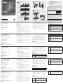
Hardware Review
A
CE700
AL
(Local Unit) Front View
CE700
AR
(Remote Unit) Front View
1. KVM Port
2. Remote LED
3. Local LED
4. Operating Mode Selection Pushbutton
5. Link LED
6. Remote LED
CE700
AL
/ CE700
AR
Rear View
CE700
AL
/ CE700
AR
Side View
1. Console Ports
2. Power Jack
3. Remote I/O
4. Grounding Terminal
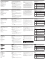
Hardware Installation
!
Make sure that the power to any device that you connect to the
installation has been turned off.
You must unplug the power cords of any computers that have the
Keyboard Power On function.
Rack Mounting
B
For convenience and flexibility, the CE700
AL
and CE700
AR
can be mounted
on system racks.
1. Using the screws provided in the Rack Mount Kit, screw the mounting
bracket into the top or bottom of the unit as shown:
2. Screw the bracket into any convenient location on the rack.
Connecting the cables
C
1. Plug the cables from the local console devices (mouse, keyboard,
monitor) into their ports on the Console section on the rear of the Local
Unit (CE700
AL
).
2. Plug the appropriate connectors on the USB KVM cable supplied with
this unit into their ports on the KVM section on the front of the Local
Unit (CE700
AL
).
3. Plug the connectors on the other end of the USB KVM cable into the
appropriate ports on the local computer.
Note: If you are combining the CE700
A
with a KVM switch, the other
end of the USB KVM cable plugs into the appropriate ports on
the KVM switch.
4. Plug one end of the Cat 5e cable into the CE700
AL
's Remote I/O port.
Plug the other end of the Cat 5e cable into the I/O port of the Remote
Unit (CE700
AR
).
5. Plug one of the power adapters (supplied with this package) into an AC
source; plug the adapter's power cable into the CE700
AL
's Power Jack
6. Plug the cables from the remote console devices into their ports on the
Console side of the CE700
AR
.
7. Plug the second power adapter (supplied with this package) into an AC
source; plug the adapter's power cable into the CE700
AR
's Power Jack.
Operation
Operating Modes
The CE700
A
USB KVM Extender system has three operating modes: Local,
Remote, and Auto, as shown in the table, below:
Mode Description
Local
Only the local console has KVM access. The remote console’s
keyboard and mouse input is disabled.
Auto
Both the local and remote consoles can have KVM access, but
not at the same time. The console without access has to wait
until the active console stops inputting data before it can gain
access.
Remote
The remote console has KVM access. Remote cannot be
selected; it can only occur when the pushbutton on the
CE700
AL
is set to Auto and the local console is idle. If the
remote console is then idle for more than five seconds, the
local console can gain access.
Note: The default operating mode is Auto.
www.aten.com
Système d'extension KVM USB CE700
A
– Guide de mise en route rapide
Description de l’appareil
A
Console locale CE700
AL
– Vue avant
Console distante CE700
AR
– Vue avant
1. Port KVM
2. Voyant de connexion distante (Remote)
3. Voyant de connexion locale (Local)
4. Bouton de sélection du mode de fonctionnement
5. Voyant de liaison (Link)
6. Voyant de connexion distante (Remote)
CE700
AL
/ CE700
AR
- Vue arrière
CE700
AL
/ CE700
AR
- Vue latérale
1. Ports de console
2. Prise d’alimentation
3. E/S distantes
4. Prise de terre
Installation du matériel
!
Vérifiez que tous les périphériques à connecter à l’installation
sont éteints.
Vous devez débrancher les cordons d’alimentation des ordinateurs
disposant de la fonction de mise sous tension via clavier.
Montage sur bâti
B
Pour plus de confort et de flexibilité, les consoles CE700
AL
et CE700
AR
peuvent être montées sur bâti.
1. Vissez le support de montage sur la partie supérieure ou inférieure de
l'appareil à l'aide des vis fournies dans le kit de montage sur bâti.
2. Vissez le support au bâti à n’importe quel endroit vous semblant
adapté.
Connexion des câbles
C
1. Branchez les câbles des périphériques de console locaux (souris, clavier
et moniteur) sur les ports correspondants de la section Console située à
l'arrière de l'unité locale CE700
AL
.
2. Insérez les connecteurs appropriés du câble USB KVM fourni avec
l'appareil dans les ports correspondants de la section KVM située à
l'avant de l'unité locale CE700
AL
.
3. Insérez les connecteurs de l'autre extrémité du câble USB KVM dans les
ports correspondants de l'ordinateur local.
Remarque: si vous combinez le système CE700
A
avec un commutateur
KVM, insérez les connecteurs de l'autre extrémité du câble
USB KVM dans les ports correspondants du commutateur
KVM.
4. Branchez une extrémité du câble de catégorie 5e sur le port E/S
distantes (Remote I/O) de l'unité locale CE700
AL
. Branchez l'autre
extrémité du câble sur le port E/S (I/O) de l'unité distante CE700
AR
.
5. Branchez l'un des adaptateurs secteur fournis sur une prise de courant
CA et sur la prise d'alimentation de l'unité locale CE700
AL
.
6. Branchez les câbles des périphériques de console distants sur les ports
correspondants de la section Console de l'unité CE700
AR
.
7. Branchez le deuxième adaptateur secteur fourni sur une prise de
courant CA et sur la prise d'alimentation du récepteur CE700
AR
.
Utilisation
Modes de fonctionnement
Le système d’extension KVM USB CE700
A
propose trois modes de
fonctionnement: Local (connexion locale), Remote (connexion distante) et
Auto (connexion automatique), décrits dans le tableau ci-dessous:
Mode Description
Local
Seule la console locale a le contrôle KVM. L'entrée du clavier
et de la souris de la console distante est désactivée.
Auto
Les deux consoles (locale et distante) peuvent prendre le
contrôle KVM, mais pas en même temps. Avant d'avoir accès,
la console n'ayant pas le contrôle doit patienter jusqu'à ce que
la console active cesse d'entrer des données.
Distant
Seule la console distante peut prendre le contrôle KVM. Le
mode distant ne peut pas être sélectionné. Il n'est disponible
que si le bouton de la console locale CE700
AL
est en position
Auto et que cette dernière est inactive. Si la console distante
est ensuite inactive pendant plus de cinq secondes, alors la
console locale peut avoir accès.
Remarque: le mode de fonctionnement par défaut est Auto.
CE700
A
USB-KVM-Verlängerung Kurzanleitung
Hardwareübersichtl
A
CE700
AL
(lokales Gerät) Vorderseite
CE700
AR
(entferntes Gerät) Vorderseite
1. KVM-Port
2. Remote-LED
3. Local-LED
4. Betriebsmodus-Auswahltaste
5. Verbindungsanzeige
6. Remote-LED
Rückseitige Ansicht des CE700
AL
/ CE700
AR
Seitenansicht des CE700
AL
/ CE700
AR
1. Konsol-ports
2. Stromeingangsbuchse
3. E/A zur Gegenstelle
4. Erdungsanschluss
Hardware installieren
!
Stellen Sie sicher, dass alle anzuschließenden Geräte
ausgeschaltet sind.
Bei Computern, die sich über die Tastatur einschalten lassen, müssen Sie
den Netzstecker ziehen.
Rack-Montage
B
Um mehr Flexibilität und Komfort zu bieten, kann der CE700
AL
bzw.
CE700
AR
im Rack eingebaut werden.
1. Verwenden Sie die mitgelieferten Schrauben, um den Montagerahmen
auf die Ober- bzw. Unterseite des Gerätes zu schrauben (siehe
Abbildung):
2. Verschrauben Sie die Halterung mit einem freien und geeignet
gelegenen Einschub am Rack.
Schließen Sie die Kabel an
C
1. Verbinden Sie die Kabel der lokalen Konsolgeräte (Maus, Tastatur,
Monitor) mit den entsprechenden Buchsen im Konsolabschnitt auf der
Rückseite des lokalen Gerätes (CE700
AL
).
2. Verbinden Sie die geeigneten Stecker des mitgelieferten USB-KVM-
Kabels mit den Buchsen im KVM-Abschnitt auf der Vorderseite des
lokalen Gerätes (CE700
AL
).
3. Verbinden Sie die Stecker am anderen Ende des USB-KVM-Kabels mit
den betreffenden Ports des lokalen Computers.
Hinweis: Wenn Sie den CE700
A
mit einem KVM-Switch kombinieren
möchten, schließen Sie das andere Ende des USB-KVM-
Kabels an die entsprechenden Ports des KVM-Switches an.
4. Verbinden Sie ein Ende des Kat. 5e-Kabels mit dem Anschluss Remote I/
O des CE700
AL
. Verbinden Sie das andere Ende des Kat. 5e-Kabels mit
dem Anschluss I/O des Gerätes der Gegenstelle (CE700
AR
).
5. Verbinden Sie das eine Ende des mitgelieferten Netzteils mit einer
Steckdose und das Netzkabel mit der Stromeingangsbuchse des
CE700
AL
.
6. Verbinden Sie die Kabel der Konsolgeräte der Gegenstelle mit den
entsprechenden Buchsen im Konsolabschnitt des CE700
AR
.
7. Verbinden Sie das zweite mitgelieferte Netzteil mit einer Steckdose und
sein Netzkabel mit der Stromeingangsbuchse des CE700
AR
.
Bedienung
Betriebsmodi
Die USB-KVM-Verlängerung CE700
A
unterstützt drei Betriebsarten: Lokal,
Automatisch und Gegenstelle, siehe folgende Tabelle:
Betriebsart Beschreibung
Lokal
Nur die lokale Konsole hat KVM-Zugriff. Die Tastatur und
die Maus der Konsole der Gegenstelle sind deaktiviert.
Automatisch
Sowohl die lokale als auch die Konsole der Gegenstelle
können die KVM-Steuerung übernehmen (allerdings
nicht gleichzeitig). Bevor sie Zugriff erhält, muss die
Konsole ohne Zugriff warten, bis die aktive Konsole die
Dateneingabe stoppt.
Gegenstelle
Nur die entfernte Konsole hat KVM-Zugriff. Die KVM-
Steuerung von der Konsole der Gegenstelle ist nur
möglich, wenn der entsprechende Drucktaster am
CE700
AL
auf Auto gestellt wurde und die lokale Konsole
nicht benutzt wird. Wird die Konsole der Gegenstelle
mehr als 5 Sekunden nicht bedient, erhält die lokale
Konsole den Zugriff.
Hinweis: Standardmäßig ist die Betriebsart auf Auto voreingestellt.
Sistema de extensión KVM USB CE700
A
Guía rápida
Presentación del hardware
A
Unidad local CE700
AL
– Vista frontal
Unidad remota CE700
AR
– Vista frontal
1. Puerto KVM
2. Indicador de conexión remota (Remote)
3. Indicador de conexión local (Local)
4. Botón de selección del modo operativo
5. Indicador de enlace (Link)
6. Indicador de conexión remota (Remote)
CE700
AL
/ CE700
AR
Vista posterior
CE700
AL
/ CE700
AR
Vista lateral
1. Puertos de consola
2. Entrada de alimentación
3. Puertos E/S para equipo remoto
4. Toma de tierra
Instalar el hardware
!
Apague todos los equipos que vaya a conectar. Si alguno de los
ordenadores utiliza la función de Encender a través del teclado,
tendrá que desconectar su cable de alimentación.
Montaje en rack
B
Para un mayor confort y más flexibilidad, el CE700
AL
y el CE700
AR
pueden
montarse en un rack.
1. Atornille como se indica en el siguiente diagrama el marco de montaje
en la parte superior o inferior de la unidad con los tornillos incluidos
con el kit para montaje en rack (véase la figura):
2. Atornille los rieles en una posición deseada del rack.
Conectar los cables
C
1. Conecte los cables de los dispositivos de consola locales (ratón, teclado
y monitor) a los puertos correspondientes de la sección de consola
situada en el panel posterior de la unidad local CE700
AL
.
2. Inserte los conectores del cable USB KVM incluido con el dispositivo
en los puertos correspondientes de la sección KVM situada en el panel
frontal de la unidad local CE700
AL
.
3. Inserte los conectores del otro extremo del cable USB KVM en los
puertos correspondientes del ordenador local.
Nota: si combina el CE700
A
con un conmutador KVM, inserte los
conectores del otro extremo del cable USB KVM en los puertos
correspondientes del conmutador KVM.
4. Conecte un extremo del cable de Cat. 5e al puerto Remote I/O de la
unidad local CE700
AL
. Conecte el otro extremo del cable al puerto I/O
de la unidad remota CE700
AR
.
5. Conecte uno de los adaptadores de alimentación incluidos a una toma
eléctrica y el cable de alimentación del adaptador a la entrada de
alimentación de la unidad local CE700
AL
.
6. Conecte los cables de los dispositivos de consola remota a los puertos
de consola del CE700
AR
.
7. Conecte el segundo adaptador de alimentación incluido a una toma
eléctrica y el cable del adaptador a la entrada de alimentación de la
unidad remota CE700
AR
.
Funcionamiento
Modos operativos
El sistema de extensión KVM USB CE700
A
ofrece tres modos operativos:
Local, Remoto y Automático, que se describen en la siguiente tabla:
Modo Descripción
Local
Sólo la consola local tiene el control KVM. La entrada del
teclado y del ratón de la consola remota está desactivada.
Auto
Tanto la consola local como la remota pueden tener el
control KVM (pero nunca las dos a la vez). Antes de obtener
acceso, la consola que no tiene el control KVM debe esperar
hasta que la consola que lo tiene deje de introducir datos.
Remoto
Sólo la consola remota tiene acceso KVM. El control KVM
remoto sólo es posible cuando el pulsador del CE700
AL
esté
en la posición Auto y no se utilice la consola local. Si la
consola remota no se utiliza durante más de cinco segundos,
la consola local obtendrá acceso.
Nota: El modo operativo predeterminado es Automático.
Hardware Review
CE700
AL
(Local Unit)
Front View
CE700
AL
/ CE700
AR
Rear View
CE700
AL
Front View
CE700
AR
(Remote Unit)
Front View
CE700
AL
/ CE700
AR
Side View
A
Hardware Installation
B
Connecting the cables
C
2
2
3
3
4
4
1
1
2
1
5 6
6
7
4
5
1
Cat 5e cable
CE700AL
CE700AR
Phillips hex head
M3 x 6
M5 x 12
(Recommended)
CE700
AL
/ CE700
AR
Rear View
1
4
5
3
6
© Copyright 2016 ATEN
®
International Co., Ltd.
ATEN and the ATEN logo are trademarks of ATEN International Co., Ltd. All rights reserved. All
other trademarks are the property of their respective owners.
This product is RoHS compliant.
Part No. PAPE-1223-582G Printing Date: 03/2016
USB KVM Extender
Quick Start Guide
CE700
A
www.aten.com
www.aten.com
www.aten.com
www.aten.com
La pagina si sta caricando...
-
 1
1
-
 2
2


in altre lingue
- English: ATEN CE700A Quick start guide
- français: ATEN CE700A Guide de démarrage rapide
- español: ATEN CE700A Guía de inicio rápido
- Deutsch: ATEN CE700A Schnellstartanleitung
- русский: ATEN CE700A Инструкция по началу работы
- português: ATEN CE700A Guia rápido
- 日本語: ATEN CE700A クイックスタートガイド