14
Chapter 5: Device Tab TOUGHSwitch
™
PoE User Guide
Ubiquiti Networks, Inc.
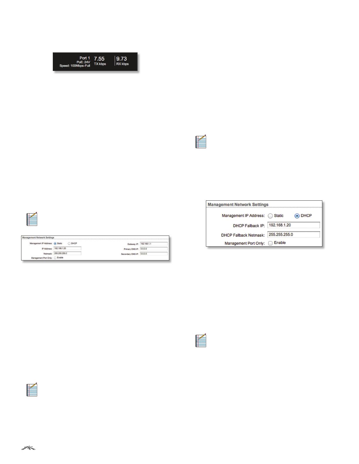
Place your mouse over a port to view its PoE status,
Speed setting, duplex mode, and statistics for TX and RX
throughput.
Save Changes To immediately save your changes, click
Save Changes.
Revert Changes To cancel your changes, click Revert
Changes.
Management Network Settings
The Management Network Settings configure the IP
settings and management access of the TOUGHSwitch.
Because the TOUGHSwitch is a Layer 2 device, the IP
Address and Netmask are not mandatory; however, if you
want to manage the TOUGHSwitch, then you will need to
configure the IP Address and Netmask unless you select
DHCP.
Management IP Address The TOUGHSwitch can use a
static IP address or obtain an IP address from its DHCP
server.
• Static Assign static IP settings to the TOUGHSwitch.
Note: IP settings should be consistent with the
address space of the TOUGHSwitch’s network
segment.
- IP Address Specify the IP address of the
TOUGHSwitch. This IP will be used for device
management purposes. The default is 192.168.1.20.
- Netmask When the netmask is expanded into its
binary form, it provides a mapping to define which
portions of the IP address range are used for the
network devices and which portions are used for host
devices. The netmask defines the address space of
the TOUGHSwitch’s network segment. The default
255.255.255.0 (or “/24”) netmask is commonly used on
many Class C IP networks.
- Management Port Only By default, this option is
disabled and you can manage the TOUGHSwitch
through any port. To restrict management access to
only the Management port, check this box.
Note: The Management Port Only option must be
disabled if you want traffic to flow between the
Management port and numbered ports. Traffic
will be limited to 10/100 Mbps and, under heavy
load, may cause performance degradation of the
TOUGHSwitch.
- Gateway IP Typically, this is the IP address of the host
router, which provides the point of connection to the
Internet. This can be a DSL modem, cable modem,
or WISP gateway router. The TOUGHSwitch directs
packets to the gateway if the destination host is not
within the local network. The default is 192.168.1.1.
- Primary DNS IP Specify the IP address of the primary
DNS (Domain Name System) server.
- Secondary DNS IP Specify the IP address of the
secondary DNS server. This entry is optional and used
only if the primary DNS server is not responding.
• DHCP The local DHCP server assigns a dynamic IP
address, netmask, gateway IP address, and DNS address
to the TOUGHSwitch.
Note: We do not recommend the DHCP option.
The IP address may change, and you will need
to use the Discovery tool from another Ubiquiti
device or computer to discover the IP address
of the TOUGHSwitch. You can also reset the
TOUGHSwitch to its factory default settings.
(Press and hold the Reset button for more than
10 seconds.) Its default IP Address is reset to
192.168.1.20.
- DHCP Fallback IP Specify the IP address the
TOUGHSwitch should use if a DHCP server is not
found. The default is 192.168.1.20.
- DHCP Fallback Netmask Specify the netmask the
TOUGHSwitch should use if a DHCP server is not
found. The default is 255.255.255.0.
- Management Port Only By default, this option is
disabled and you can manage the TOUGHSwitch
through any port. To restrict management access to
only the Management port, check this box.
Note: The Management Port Only option must be
disabled if you want traffic to flow between the
Management port and numbered ports. Traffic
will be limited to 10/100 Mbps and, under heavy
load, may cause performance degradation of the
TOUGHSwitch.


