
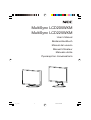
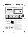
MultiSync LCD205WXM
MultiSync LCD225WXM
User’s Manual
Bedienerhandbuch
Manual del usuario
Manuel Utilisateur
Manuale utente
Руководство пользователя
00_Cover 6/6/07, 8:36 AM1

TCO’03
Congratulations!
The display you have just purchased carries the TCO’03 Displays
label. This means that your display is designed, manufactured and
tested according to some of the strictest quality and environmental
requirements in the world. This makes for a high performance
product, designed with the user in focus that also minimizes the
impact on our natural environment.
Some of the features of the TCO’03 Display requirements:
Ergonomics
• Good visual ergonomics and image quality in order to improve the working environment for
the user and to reduce sight and strain problems. Important parameters are luminance,
contrast, resolution, reflectance, color rendition and image stability.
Energy
• Energy-saving mode after a certain time – beneficial both for the user and the environment
• Electrical safety
Emissions
• Electromagnetic fields
• Noise emissions
Ecology
• The product must be prepared for recycling and the manufacturer must have a certified
environmental management system such as EMAS or ISO 14 001
• Restrictions on:
- chlorinated and brominated flame retardants and polymers
- heavy metals such as cadmium, mercury and lead.
The requirements included in this label have been developed by TCO Development in co-operation
with scientists, experts, users as well as manufacturers all over the world. Since the end of the
1980s TCO has been involved in influencing the development of IT equipment in a more user-
friendly direction. Our labelling system started with displays in 1992 and is now requested by users
and IT-manufacturers all over the world.
For more information, please visit
www.tcodevelopment.com
00_Cover 6/6/07, 8:36 AM2

Manufacturer’s Recycling and Energy Information
NEC DISPLAY SOLUTIONS is strongly committed to environmental protection and sees recycling
as one of the company’s top priorities in trying to minimize the burden placed on the environment.
We are engaged in developing environmentally-friendly products, and always strive to help define
and comply with the latest independent standards from agencies such as ISO (International
Organisation for Standardization) and TCO (Swedish Trades Union).
Disposing of your old NEC product
The aim of recycling is to gain an environmental benefit by means of re-use, upgrading,
reconditioning or reclamation of material. Dedicated recycling sites ensure that environmentally
harmful components are properly handled and securely disposed. To ensure the best recycling of
our products, NEC DISPLAY SOLUTIONS offers a variety of recycling procedures and gives
advice on how to handle the product in an environmentally sensitive way, once it has reached the
end of its life.
All required information concerning the disposal of the product and country-specific information on
recycling facilities can be found on our following websites:
http://www.nec-display-solutions.com/greencompany/ (in Europe),
http://www.nec-display.com (in Japan) or
http://www.necdisplay.com (in USA).
Energy Saving
This monitor features an advanced energy saving capability. When a VESA Display Power
Management Signalling (DPMS) Standard signal is sent to the monitor, the Energy Saving mode is
activated. The monitor enters a single Energy Saving mode.
WEEE Mark (European Directive 2002/96/EC)
Within the European Union
EU-wide legislation, as implemented in each Member State, requires that waste
electrical and electronic products carrying the mark (left) must be disposed of
separately from normal household waste. This includes monitors and electrical
accessories, such as signal cables or power cords. When you need to dispose of
your NEC display products, please follow the guidance of your local authority, or
ask the shop where you purchased the product, or if applicable, follow any
agreements made between yourself and NEC.
The mark on electrical and electronic products only applies to the current European Union Member
States.
Outside the European Union
If you wish to dispose of used electrical and electronic products outside the European Union, please
contact your local authority so as to comply with the correct disposal method.
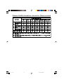
Mode Power consumption LED color
Normal Operation Approx. 45W (LCD205WXM) Green
Approx. 48W (LCD225WXM)
Energy Saving Mode Less than 2W Orange
Off Mode Less than 1W Unlit
00_Cover 6/6/07, 8:36 AM3

Chinese RoHS-information relevant for Chinese market
00_Cover 6/6/07, 8:36 AM4

English-1
English
Declaration of the Manufacturer
We hereby certify that the color monitor MultiSync LCD205WXM
(L206T8)/MultiSync LCD225WXM (L226T9) are in compliance with
Council Directive 73/23/EEC:
– EN 60950-1
Council Directive 89/336/EEC:
– EN 55022
– EN 61000-3-2
– EN 61000-3-3
– EN 55024
RISK OF ELECTRIC SHOCK • DO NOT OPEN
TO PREVENT FIRE OR SHOCK HAZARDS, DO NOT EXPOSE THIS UNIT TO RAIN OR MOISTURE. ALSO, DO NOT USE THIS UNIT’S
POLARIZED PLUG WITH AN EXTENSION CORD RECEPTACLE OR OTHER OUTLETS UNLESS THE PRONGS CAN BE FULLY INSERTED.
REFRAIN FROM OPENING THE CABINET AS THERE ARE HIGH VOLTAGE COMPONENTS INSIDE. REFER SERVICING TO QUALIFIED
SERVICE PERSONNEL.
WARNING
CAUTION: TO REDUCE THE RISK OF ELECTRIC SHOCK,
DO NOT REMOVE COVER (OR BACK). NO USER
SERVICEABLE PARTS INSIDE. REFER SERVICING
TO QUALIFIED SERVICE PERSONNEL.
This symbol warns user that uninsulated voltage
within the unit may have sufficient magnitude to cause
electric shock. Therefore, it is dangerous to make any
kind of contact with any part inside this unit.
This symbol alerts the user that important literature
concerning the operation and maintenance of this
unit has been included. Therefore, it should be read
carefully in order to avoid any problems.
CAUTION
and marked with
NEC Display Solutions, Ltd.
4-13-23, Shibaura,
Minato-Ku
Tokyo 108-0023, Japan
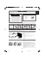
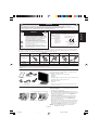
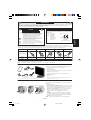
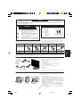
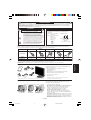
Contents
Your new NEC MultiSync LCD monitor box* should contain the
following:
• MultiSync LCD monitor with tilt base
• Audio Cable
• Power Cord
•Video Signal Cable (15-pin mini D-SUB male to 15-pin mini
D-SUB male)
•Video Signal Cable (DVI-D to DVI-D) (for Europe)
• User’s Manual
• CD-ROM
*
Remember to save your original box and packing material to transport or ship
the monitor.
User’s
Manual
Audio
Cable
Power Cord*
15-pin mini D-SUB
male to 15-pin mini
D-SUB male
DVI-D to DVI-D
(for Europe)
MultiSync LCD monitor
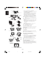
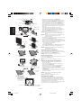
Quick Start
To attach the MultiSync LCD monitor to your system, follow these
instructions:
1. Turn off the power to your computer.
2. For the PC or MAC with DVI digital output: Connect the DVI-D
signal cable (not included for the U.S. and China) to the connector of
the display card in your system (Figure A.1). Tighten all screws.
For the PC with Analog output: Connect the 15-pin mini D-SUB
signal cable to the connector of the display card in your system
(Figure A.2). Tighten all screws.
For the MAC: Connect the MultiSync Macintosh cable adapter
(not included) to the computer. Attach the 15-pin mini D-SUB signal
cable to the MultiSync Macintosh cable adapter (Figure A.3).
Tighten all screws.
NOTE: Some Macintosh systems do not require a Macintosh cable
adapter.
Figure A.1 Figure A.2
Macintosh Cable Adapter (not included)
CD-ROM
Figure A.3
User’s
Manual
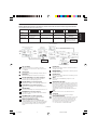
* Type of power cord included will depend on the where the LCD monitor is to be shipped.
CAUTION: Please use the power cord provided with this display in accordance with the table below. If a power cord is not supplied with this
equipment, please contact your supplier. For all other cases, please use a power cord that matches the AC voltage of the power outlet and has
been approved by and complies with the safety standard of your particular country.
Plug Type North America
European Continental
U.K. Chinese Japanese
Plug Shape
Country
Voltage
U.S.A./Canada U.K. China JapanEU (except U.K.)
120*
230 220 100230
* When operating the MultiSync LCD205WXM/LCD225WXM monitor with its AC 125-240V power supply, use a power supply cord that matches
the power supply voltage of the AC power outlet being used.
NOTE: This product can only be serviced in the country where it was purchased.
01_English 6/6/07, 8:36 AM1

English-2
English
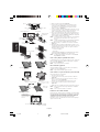
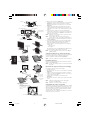
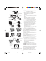
Figure C.1
Power Button
Figure TS.1
Figure R.1
Non-abrasive surface
Figure R.2
Figure R.3
4-SCREWS (M4)
MAX depth: 8.5mm
If use other screw,
check length of screw.
Weight of LCD assembly: 6.0 kg (MAX) (LCD205WXM)
6.3 kg (MAX) (LCD225WXM)
Specifications
Replace screws
Tighten all
screws
100 mm
Thickness
of Bracket (Arm)
2.0 ~ 3.2 mm
3. Remove the Cable management cover (Figure A.4).
4. Connect all cables to the appropriate connector on the back of the
monitor (Figure B.1). Connect Headphones
(not included) to the appropriate connector at the rear side of the
monitor, if desired (Figure B.1).
5. Connect one end of the power cord to the monitor and the other
end to the power outlet. Position the Video Signal Cable, Audio
cable and power cord between the holes on the Stand.
6. To attach the Cable management cover, insert the tabs of the
Cable management cover into the holes on the Stand and slide
the Cable management cover downward into place (Figure B.1)
making sure that the tabs are completely secure.
NOTE: Adjust the position of the cables that are placed under the
Cable management cover to avoid damaging the cable or
monitor.
NOTE: Please refer to the Caution section of this manual for proper
selection of power cord.
7. Turn on the monitor with the front power button and the computer
(Figure C.1).
8. No-touch Auto Adjust automatically adjusts the monitor to optimal
settings upon initial setup for most timings (Analog input only).
For further adjustments, use the following OSD controls:
• Auto Contrast
• Auto Adjust
Refer to the Controls section of this User’s Manual for a full
description of these OSD controls.
NOTE: If you have any problem, please refer to the
Troubleshooting section (CD-ROM).
Raise and Lower Monitor Screen
The monitor may be raised or lowered. To raise or lower screen, place
hands on each side of the monitor and lift or lower to the desired
height (Figure RL.1).
NOTE: Handle with care when raising or lowering the monitor
screen.
Tilt and Swivel
Grasp both sides of the monitor screen with your hands and adjust
the tilt and swivel as desired (Figure TS.1).
NOTE:
Handle with care when tilting and swivelling the monitor screen.
Remove Monitor Stand for Mounting
To prepare the monitor for alternative mounting purposes:
1. Disconnect all cables.
2. Place monitor face down on a non-abrasive surface (Figure R.1).
3. Remove the 4 screws connecting the monitor to the stand and
remove the stand as indicated (Figure R.2). The monitor is now
ready for mounting in an alternative manner.
4. Connect all cables to the back of the monitor (Figure R.3).
5. Reverse this process to re-attach stand.
NOTE: Use only VESA-compatible alternative mounting method.
NOTE: Handle with care when removing monitor stand.
Connecting a Flexible Arm
This LCD monitor is designed for use with a flexible arm.
Please use the attached screws (4pcs) as shown in the picture when
installing. To meet the safety requirements, the monitor must be
mounted to an arm which guaranties the necessary stability under
consideration of the weight of the monitor. The LCD monitor shall only
be used with an approved arm (e.g. GS mark).
100 mm
Figure RL.1
Base
Stand
Cable management cover
Figure A.4
Power Cable
Cable
management
cover
Connect to Computer
audio output
Figure B.1
Input (VGA)
Input (Audio)
Input (DVI)
Headphone
01_English 6/6/07, 8:36 AM2

English-3
English
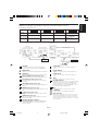
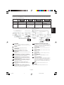
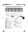
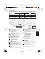
Controls
OSD (On-Screen-Display) control buttons on the front of the monitor function as follows:
1. Basic function at pressing each key
Showing OSD. Shortcut to Brightness
adjust Menu.
Button
At No OSD
showing
Shortcut to Volume adjust
Menu.
At OSD showing
(Icon selection stage)
Go to Adjustment stage. Cursor goes to left. Cursor goes to right.
At OSD showing
(Adjustment stage)
Go to Icon selection stage. Adjust value decrease or
Cursor for adjust goes to
left.
Adjust value increase or
Cursor for adjust goes to
right.
SELECT
– +
Input signal select.
Reset operation.
Mute off/on switch on
Volume adjustment Menu.
1<->2 / RESET
Sub Menu
(Icon Select)
Press
“–” or “+”
Sub Menu (Adjust)
Press “SELECT” key
Press
“–” or “+”
Example Tool:
Press “SELECT” key
Press “SELECT” key
Main Menu
(Icon Select, Analog Input)
Main Menu (Adjust)
Press
“SELECT”
key
Press
“SELECT”
key
Press “SELECT” key
Adjust by using
“–” or “+”
Adjust by using
“–” or “+”
VOLUME
Control the sound volume of speakers and headphone.
To mute the speaker sound, press the 1<->2/RESET key.
BRIGHTNESS
Adjusts the overall image and background screen brightness.
CONTRAST
Adjusts the image brightness in relation to the background.
AUTO CONTRAST (Analog Input only)
Adjusts the image displayed for non-standard video inputs.
AUTO ADJUST (Analog Input only)
Automatically adjusts the Image Position, the H. Size and
Fine setting.
LEFT/RIGHT (Analog Input only)
Controls Horizontal Image Position within the display area of
the LCD.
DOWN/UP (Analog Input only)
Controls Vertical Image Position within the display area of the
LCD.
H. SIZE (Analog Input only)
Adjusts the horizontal size by increasing or decreasing this
setting.
FINE (Analog Input only)
Improves focus, clarity and image stability by increasing or
decreasing this setting.
COLOR CONTROL SYSTEMS
Five color presets (9300/7500/sRGB/USER/NATIVE) select
the desired color setting.
The sRGB and NATIVE, color presets are standard and
cannot be changed.
COLOR RED
Increase or decreases Red. The change will appear on
screen.
COLOR GREEN
Increase or decreases Green. The change will appear on
screen.
COLOR BLUE
Increase or decreases Blue. The change will appear on
screen.
TOOL
Selecting TOOL allows you to get into the sub menu.
FACTORY PRESET
Selecting Factory Preset allows you to reset all OSD control
settings back to the factory settings. The RESET button will
need to be held down for several seconds to tage effect.
Individual settings can be reset by highlighting the control to
be reset and pressing the RESET button.
EXIT
Selecting EXIT allows you exit OSD menu/ sub menu.
LANGUAGE
OSD control menus are available in nine languages.
OSD TURN OFF
The OSD control menu will stay on as long as it is in use. In
the OSD Turn OFF submenu, you can select how long the
monitor waits after the last touch of a button to shut off the
OSD control menu. The preset choices are 10 - 120 seconds
by 5 seconds step.
2. OSD structure
01_English 6/6/07, 8:37 AM3

English-4
English
OSD LOCK OUT
This control completely locks out access to all OSD control
functions without Volume, Brightness and Contrast. When
attempting to activate OSD controls while in the Lock Out
mode, a screen will appear indicating the OSD are locked
out. To activate the OSD Lock Out function, press “1<->2/
RESET”, then “+” key and hold down simultaneously. To de-
activate the OSD Lock Out, press “1<->2/ RESET”, then “+”
key and hold down simultaneously.
RESOLUTION NOTIFIER
If ON is selected, a message will appear on the screen after
45 seconds, notifying you that the resolution is not at optimal
resolution.
MONITOR INFO
Indicates the model and serial numbers of your monitor.
EXPANSION
Selects the zoom mode.
FULL: The image is expanded to 1680 x 1050, regardless of
resolution.
ASPECT: The image is expended without changing the
aspect ratio.
DDC/CI
Turns ON or OFF the two way communication and control of
the monitor.
INPUT RESOLUTION (Analog Input Only)
Sets of the resolution of input signal to one of the following:
When vertical active size is 768, you can select resolution
from 1024 x 768, 1280 x 768, 1360 x 768.
When vertical active size is 1050, you can select resolution
from 1400 x 1050, 1680 x 1050.
OSD Warning
OSD Warning menus disappear with SELECT button.
NO SIGNAL: This function gives a warning when there is no
signal present. After power is turned on or when there is a
change of input signal or video is inactive, the No Signal
window will appear.
RESOLUTION NOTIFIER: This function gives a warning of
use with optimized resolution. After power is turned on or
when there is a change of input signal or the video signal
doesn’t have proper resolution, the Resolution Notifier
window will open. This function can be disabled in the TOOL
menu.
OUT OF RANGE: This function gives a recommendation of
the optimized resolution and refresh rate. After the power is
turned on or there is a change of input signal or the video
signal doesn’t have proper timing, the Out Of Range menu
will appear.
01_English 6/6/07, 8:37 AM4

Deutsch-1
Deutsch
Erklärung des Herstellers
Wir bestätigen hiermit, dass die Monitore MultiSync LCD205WXM
(L206T8) sowie MultiSync LCD225WXM (L226T9) folgenden
Richtlinien entsprechen:
EG-Direktive 73/23/EG:
– EN 60950-1
EG-Direktive 89/336/EG:
– EN 55022
– EN 61000-3-2
– EN 61000-3-3
– EN 55024
STROMSCHLAGGEFAHR • NICHT ÖFFNEN
SETZEN SIE DAS GERÄT WEDER REGEN NOCH FEUCHTIGKEIT AUS, DA ES ANDERNFALLS ZU FEUER ODER STROMSCHLÄGEN KOMMEN
KANN. VERWENDEN SIE DEN NETZSTECKER DIESES GERÄTS KEINESFALLS MIT EINEM VERLÄNGERSKABEL ODER EINER
STECKDOSENLEISTE, WENN DIE STECKERSTIFTE NICHT VOLLSTÄNDIG EINGEFÜHRT WERDEN KÖNNEN.
ÖFFNEN SIE DAS GEHÄUSE NICHT, DA SICH IM INNEREN KOMPONENTEN BEFINDEN, DIE UNTER HOCHSPANNUNG STEHEN. LASSEN SIE
WARTUNGSARBEITEN VON QUALIFIZIERTEN WARTUNGSTECHNIKERN DURCHFÜHREN.
WARNUNG
VORSICHT: ENTFERNEN SIE KEINESFALLS ABDECKUNG ODER
RÜCKSEITE, DAMIT ES NICHT ZU STROMSCHLÄGEN
KOMMT. IM INNEREN BEFINDEN SICH KEINE VOM
BENUTZER ZU WARTENDEN KOMPONENTEN. LASSEN
SIE WARTUNGSARBEITEN VON QUALIFIZIERTEN
WARTUNGSTECHNIKERN DURCHFÜHREN.
Dieses Symbol weist den Benutzer auf nicht isolierte
spannungsführende Komponenten im Gerät hin, die
Stromschläge verursachen können. Aus diesem Grund
dürfen Sie keinesfalls Kontakt mit einer Komponente im
Geräteinneren herstellen.
Dieses Symbol weist den Benutzer auf wichtige
Informationen zu Betrieb und Pflege dieses Geräts hin.
Die Informationen sollten sorgfältig gelesen werden, um
Probleme zu vermeiden.
VORSICHT
und mit folgendem Siegel
gekennzeichnet ist:
NEC Display Solutions, Ltd.
4-13-23, Shibaura,
Minato-Ku
Tokyo 108-0023, Japan
Inhalt der Verpackung
Der Karton* mit Ihrem neuen NEC MultiSync LCD-Monitor sollte
folgende Komponenten enthalten:
• MultiSync LCD-Monitor mit verstellbarem Fuß
• Audiokabel
• Netzkabel
• Signalkabel (Mini-D-SUB-Stecker mit 15 Stiften an beiden Seiten)
• Signalkabel (DVI-D auf DVI-D) (für Europa)
• Bedienungsanleitung
• CD-ROM
*
Bewahren Sie den Originalkarton und das Verpackungsmaterial für spätere
Transporte des Monitors auf.
Kurzanleitung
Gehen Sie folgendermaßen vor, um den MultiSync LCD-Monitor an Ihr
System anzuschließen:
1. Schalten Sie Ihren Computer aus.
2. PC oder Mac mit digitalem DVI-Ausgang: Verbinden Sie das
DVI-D-Signalkabel (nicht mitgeliefert für USA und China) mit dem
Anschluss der Grafikkarte in Ihrem System (Abbildung A.1).
Ziehen Sie die Schrauben fest.
PC mit analogem Ausgang: Verbinden Sie den Mini-D-SUB-
Stecker (15 Stifte) des entsprechenden Signalkabels mit dem
Anschluss der Grafikkarte in Ihrem System (Abbildung A.2).
Ziehen Sie die Schrauben fest.
Mac: Schließen Sie den MultiSync-Kabeladapter für Macintosh
(nicht mitgeliefert) an den Computer an. Stecken Sie den Mini-D-
SUB-Stecker (15 Stifte) des Signalkabels in den Macintosh-
Kabeladapter (Abbildung A.3). Ziehen Sie die Schrauben fest.
HINWEIS: Für einige Macintosh-Systeme ist kein Macintosh-
Kabeladapter erforderlich.
Abbildung A.1 Abbildung A.2
Macintosh-Kabeladapter (nicht mitgeliefert)
Abbildung A.3
Bedienung-
sanleitung
Audio-
kabel
Netzkabel*
Mini-D-SUB-Stecker
mit 15 Stiften an
beiden Seiten
DVI-D auf DVI-D
(für Europa)
MultiSync LCD-Monitor
CD-ROM
* Welcher Netzkabeltyp mitgeliefert wird, hängt davon ab, wohin der LCD-Monitor geliefert wird
VORSICHT: Bitte verwenden Sie das mit diesem Monitor gelieferte Netzkabel gemäß der folgenden Tabelle. Setzen Sie sich mit Ihrem Händler in
Verbindung, wenn der Monitor ohne Netzkabel geliefert wurde. In allen anderen Fällen ist ein für die Netzspannung geeignetes und zugelassenes
Netzkabel zu verwenden, dass den Sicherheitsstandards des betreffenden Landes entspricht.
Steckertyp Nordamerika
Europäisch
(Kontinent)
Großbritannien Chinesisch Japanisch
Steckerform
Land
Spannung
USA/Kanada Großbritannien China JapanEU (außer GB)
120*
230 220 100230
* Verwenden Sie ein Netzkabel, das dem Spannungswert der Netzsteckdose entspricht, wenn Sie für den MultiSync LCD205WXM/
LCD225WXM-Monitor das 125-240-V-Wechselstromnetzteil verwenden.
HINWEIS: Für dieses Produkt werden Kundendienstleistungen nur in dem Land angeboten, in dem Sie es gekauft haben.
Bedienung-
sanleitung
02_German 6/6/07, 8:37 AM1

Deutsch-2
Deutsch
Abbildung C.1
Netzschalter
Abbildung TS.1
Abbildung R.1
Weiche Oberfläche
Abbildung R.2
Abbildung R.3
4 SCHRAUBEN (M4)
Maximale Tiefe: 8,5 mm
Wenn Sie eine andere
Schraube verwenden,
prüfen Sie bitte die
Länge der Schraube.
Gewicht des LCD-Monitors komplett: 6,0 kg (max.) (LCD205WXM)
6,3 kg (max.) (LCD225WXM)
Technische Daten
Schrauben anbringen
Alle Schrauben
festziehen
100 mm
Stärke der Halterung
(Arm) 2,0 ~ 3,2 mm
100 mm
Abbildung RL.1
3. Entfernen Sie die Kabelabdeckung (Abbildung A.4).
4. Verbinden Sie alle Kabel mit den entsprechenden Anschlüssen auf
der Rückseite des Monitors (Abbildung B.1). Schließen Sie die
Kopfhörer (nicht mitgeliefert) an die entsprechende Buchse auf der
Rückseite des Monitors an, wenn gewünscht (Abbildung B.1).
5. Stecken Sie ein Ende des Netzkabels in den Monitor und das
andere Ende in die Steckdose. Führen Sie das Videosignalkabel,
das Audiokabel und das Netzkabel durch die Aussparungen im
Monitorfuß.
6. Um die Kabelabdeckung anzubringen, stecken Sie die
Verriegelungen der Kabelabdeckung in die Aussparungen im
Monitorfuß und schieben die Abdeckung in die korrekte Position
nach unten (Abbildung B.1). Achten Sie darauf, dass die
Verriegelungen komplett eingerastet sind.
HINWEIS: Richten Sie die Kabel unter der Kabelabdeckung so aus,
dass weder Kabel noch Monitor beschädigt werden
können.
HINWEIS: Beachten Sie zur Auswahl des richtigen Netzkabels den
entsprechenden Sicherheitshinweis in dieser
Bedienungsanleitung.
7. Schalten Sie den Computer und den Monitor mit dem Netzschalter
an der Vorderseite (Abbildung C.1) ein.
8. Die berührungslose Einstellungsautomatik nimmt beim ersten
Setup für die meisten Timings die optimalen Einstellungen für den
Monitor vor (nur analoger Eingang). Weitere Anpassungen werden
mit den folgenden OSD Steuerungen vorgenommen:
• Automatische Kontrasteinstellung
• Automatische Einstellung
Im Abschnitt Bedienelemente dieser Bedienungsanleitung finden
Sie eine ausführliche Beschreibung der OSD-Steuerungen.
HINWEIS: Sollten Probleme auftreten, beachten Sie den Abschnitt
Fehlerbehebung (CD-ROM).
Heben und Senken des Bildschirms
Der Monitor kann gehoben oder gesenkt werden. Fassen Sie den
Monitor zu diesem Zweck auf beiden Seiten an und heben oder senken
Sie ihn auf die gewünschte Höhe (Abbildung RL.1).
HINWEIS: Heben und senken Sie den Monitor vorsichtig.
Neigen und Schwenken
Fassen Sie den Monitor an beiden Seiten und neigen bzw. drehen Sie
ihn nach Bedarf (Abbildung TS.1).
HINWEIS: Neigen und drehen Sie den Monitor vorsichtig.
Entfernen des Monitorfußes für die Montage
So bereiten Sie den Monitor für eine alternative Montage vor:
1. Ziehen Sie alle Kabel ab.
2. Legen Sie den Monitor mit der Vorderseite nach unten auf eine
weiche Oberfläche (Abbildung R.1).
3. Entfernen Sie die 4 Schrauben, mit denen der Fuß am Monitor
befestigt ist, und heben Sie den Fuß ab (Abbildung R.2).
Der Monitor kann jetzt auf andere Art montiert werden.
4. Schließen Sie Netz- und Signalkabel an der Rückseite des Monitors
an (Abbildung R.3).
5. Führen Sie die Schritte in umgekehrter Reihenfolge aus, um den
Fuß wieder anzubringen.
HINWEIS: Verwenden Sie ausschließlich VESA-kompatible
Montagemethoden.
HINWEIS: Entfernen Sie den Monitorfuß vorsichtig.
Befestigen eines Tragarms
Dieser LCD-Monitor kann mit einem Tragarm verwendet werden.
Verwenden Sie die beigefügten Schrauben (4 Stück) für die Montage,
wie es in der Abbildung dargestellt ist. Die Sicherheitsvorschriften
verlangen, dass der Monitor an einem Tragarm montiert wird, der für
das Gewicht des Monitors ausreichend stabil ist.
Der LCD-Monitor darf nur auf einem zugelassenen Arm montiert werden,
der beispielsweise mit einem GS-Zeichen versehen ist.
Standfuß
Monitorfuß
Kabelabdeckung
Abbildung A.4
Netzkabel Eingang (VGA)
Kabelabdeckung
An Audio-Ausgang des
Computers anschließen
Abbildung B.1
Eingang (Audio)
Kopfhörer
Eingang (DVI)
02_German 6/6/07, 8:37 AM2

Deutsch-3
Deutsch
2. OSD Struktur
Bedienelemente
Die OSD Bedienelemente (On-Screen-Display) auf der Vorderseite des Monitors haben folgende Funktionen:
1. Basisfunktion beim Betätigen der jeweiligen Taste
Zeigt den OSD an. Öffnet das Fenster für die
Helligkeitseinstellung.
Taste
Ohne OSD-
Anzeige
Öffnet das Fenster für die
Lautstärkeeinstellung.
Mit OSD-Anzeige
(
Symbolauswahlmodus
)
Wechselt zur
Einstellungsphase.
Cursor nach links. Cursor nach rechts.
Mit OSD-Anzeige
(Einstellungsmodus)
Wechselt zum
Symbolauswahlmodus.
Verringert den Wert oder
bewegt Cursor nach links.
Erhöht den Wert oder
bewegt Cursor nach rechts.
SELECT
– +
Auswahl des
Eingangssignals.
Zurücksetzen der Einstellung.
Schaltet im Menü für die
Lautstärkeeinstellung die
Stummschaltung ein/aus.
1<->2/RESET
Untermenü
(Symbolauswahl)
Taste „–“
oder „+“
drücken
Untermenü (Einstellungen)
Taste „SELECT“ drücken
Taste „–“
oder „+“
drücken
Taste „SELECT“ drücken
Taste „SELECT“ drücken
Hauptmenü (Symbolauswahl,
Analogeingang)
Hauptmenü
(Einstellungen)
Taste
„SELECT“
drücken
Taste
„SELECT“
drücken
Taste „SELECT“ drücken
Mit „–“ oder „+“
einstellen
Mit „–“ oder „+“
einstellen
LAUTSTÄRKE
Lautstärke für Lautsprecher und Kopfhörer einstellen.
Um die Lautsprecher auszuschalten, drücken Sie die Taste
1<->2/RESET.
HELLIGKEIT
Passt die Bild- und Hintergrundhelligkeit des Bildschirms an.
KONTRAST
Ändert die Bildhelligkeit im Verhältnis zum Hintergrund.
AUTOM. KONTRAST (nur Analogeingang)
Passt das angezeigte Bild bei Verwendung nicht dem
Standard entsprechender Eingangssignale an.
AUTOM. EINST (nur Analogeingang)
Stellt Bildposition, Bildbreite und Optimierung automatisch ein.
LINKS/RECHTS (nur Analogeingang)
Steuert die horizontale Bildposition im Anzeigebereich des
LCD.
UNTEN/OBEN
Steuert die vertikale Bildposition im Anzeigebereich des LCD.
BILDBREITE (nur Analogeingang)
Durch Erhöhen oder Verringern dieses Werts wird das Bild
breiter bzw. schmaler.
OPTIMIERUNG (nur Analogeingang)
Optimiert Schärfe, Deutlichkeit und Bildstabilität durch
Erhöhen oder Verringern dieses Werts.
FARBSTEUERUNGSSYSTEM
Fünf Voreinstellungen (9300/7500/sRGB/BENUTZER/
ORIGINALFARBEN) wählen die gewünschte Farbeinstellung
aus. Die Farbeinstellungen sRGB und ORIGINALFARBEN
sind Standardeinstellungen und können nicht angepasst
werden.
FARBE ROT
Erhöht oder verringert den Rotanteil. Die Änderung wird auf
dem Bildschirm sichtbar.
FARBE GRÜN
Erhöht oder verringert den Grünanteil. Die Änderung wird auf
dem Bildschirm sichtbar.
FARBE BLAU
Erhöht oder verringert den Blauanteil. Die Änderung wird auf
dem Bildschirm sichtbar.
TOOL
Durch Auswahl von WERKZEUG gelangen Sie in das
Untermenü.
WERKSEINSTELLUNG
Mit der OSD-Steuerung „Werkseinstellung“ werden alle OSD-
Einstellungen auf die Werkseinstellungen zurückgesetzt. Sie
müssen die Taste RESET mehrere Sekunden halten, um die
Rücksetzung durchzuführen. Einzelne Einstellungen können
durch Markieren der betreffenden Steuerung und
anschließendes Drücken der Taste RESET zurückgesetzt
werden.
EXIT
Mit „EXIT“ verlassen Sie das OSD Menü/Untermenü.
SPRACHE
Die OSD-Menüs sind in neun Sprachen verfügbar.
OSD ANZEIGEDAUER
Das OSD Steuerungsmenü wird ausgeblendet, wenn es nicht
mehr verwendet wird. Im Untermenü „OSD Anzeigedauer”
können Sie festlegen, nach welchem Zeitraum das OSD
Steuerungsmenü ausgeblendet wird, wenn der Benutzer
keine Taste drückt. Die Voreinstellungen reichen von
10 – 120 Sekunden in 5-Sekunden-Abständen.
Beispiel WERKZEUG:
02_German 6/6/07, 8:37 AM3

Deutsch-4
Deutsch
OSD ABSCHALTUNG
Mit „OSD Abschaltung“ werden alle OSD-Funktionen bis auf
Lautstärke, Helligkeit und Kontrast gesperrt. Wenn Sie im
Modus „OSD Abschaltung“ auf die OSD Steuerungen
zugreifen, wird ein Bildschirm angezeigt, der auf die Sperre
der OSD Steuerungen hinweist. Um die Funktion „OSD
Abschaltung“ zu aktivieren, halten Sie die Tasten 1<->2/
RESET und „+“ gleichzeitig gedrückt. Um die Funktion
„OSD Abschaltung“ wieder zu deaktivieren, drücken Sie
erneut die Taste 1<->2/RESET und gleichzeitig die Taste „+“.
AUFLÖSUNGSANZEIGE
Wenn Sie AN auswählen, wird nach 45 Sekunden eine
Meldung auf dem Bildschirm angezeigt, wenn der Monitor
nicht auf die optimale Auflösung eingestellt ist.
AUSDEHNUNG
Dient zum Auswählen des Zoom-Modus.
VOLLBILD: Die Bilddarstellung wird unabhängig von der
Auflösung auf 1680 x 1050 Pixel erweitert.
SEITENMASSE: Das Bild wird vergrößert, ohne dass das
Seitenverhältnis geändert wird.
DDC/CI
Schaltet die 2-Wege-Kommunikation und die Steuerung des
Monitors EIN oder AUS.
MONITORINFORMATION
Die Modell- und die Seriennummer des Monitors.
EINGANGSAUFLÖSUNG (nur analoger
Eingang)
Legt die Auflösung des Eingangssignals auf eine der
folgenden Einstellungen fest:
Wenn die aktive Bildhöhe 768 ist, können Sie zwischen
folgenden Auflösungen wählen: 1024 x 768, 1280 x 768,
1360 x 768.
Wenn die aktive Bildhöhe 1050 ist, können Sie zwischen
folgenden Auflösungen wählen: 1400 x 1050, 1680 x 1050.
OSD Warnung
Die Menüs der OSD Warnungen können mit der Taste
„SELECT“ ausgeblendet werden.
KEIN SIGNAL: Diese Funktion gibt eine Warnung aus, wenn
kein Signal verfügbar ist. Das Fenster Kein Signal wird nach
dem Einschalten oder einem Wechsel des Eingangssignals
sowie dann angezeigt, wenn kein Videosignal verfügbar ist.
AUFLÖSUNGSANZEIGE: Diese Funktion warnt Sie, wenn
nicht die optimale Auflösung verwendet wird. Nach dem
Einschalten, nach einer Änderung des Videosignals oder
wenn das Videosignal nicht die richtige Auflösung besitzt,
wird das Fenster Auflösungsanzeige angezeigt. Diese
Funktion kann im Hilfsfunktionenmenü deaktiviert werden.
FREQUENZ ZU HOCH: Diese Funktion empfiehlt die
optimale Auflösung und Bildwiederholrate. Nach dem
Einschalten, nach einer Änderung des Eingangssignals oder
wenn das Videosignal nicht die richtige Auflösung besitzt,
wird das Fenster Frequenz zu hoch angezeigt.
02_German 6/6/07, 8:37 AM4

Español-1
Español
Declaración del fabricante
Por la presente certificamos que los monitores en color MultiSync
MultiSync LCD205WXM (L206T8)/MultiSync LCD225WXM (L226T9)
cumplen con la
Directiva 73/23/CEE:
– EN 60950-1
Directiva 89/336/CEE:
– EN 55022
– EN 61000-3-2
– EN 61000-3-3
– EN 55024
RIESGO DE DESCARGAS ELÉCTRICAS • NO ABRIR
PARA PREVENIR EL PELIGRO DE INCENDIO O DESCARGAS ELÉCTRICAS, NO EXPONGA ESTE PRODUCTO A LA LLUVIA O LA HUMEDAD.
TAMPOCO UTILICE EL ENCHUFE POLARIZADO DE ESTE PRODUCTO CON UN RECEPTÁCULO DEL CABLE DE EXTENSIÓN U OTRAS TOMAS A
MENOS QUE LAS PROLONGACIONES SE PUEDAN INSERTAR COMPLETAMENTE.
NO ABRA LA CAJA DEL MONITOR, YA QUE CONTIENE COMPONENTES DE ALTO VOLTAJE. DEJE QUE SEA EL PERSONAL DE SERVICIO
CUALIFICADO QUIEN SE ENCARGUE DE LAS TAREAS DE SERVICIO.
ADVERTENCIA
PELIGRO: PARA REDUCIR EL RIESGO DE DESCARGAS
ELÉCTRICAS, NO RETIRE LA CUBIERTA (O LA PARTE
POSTERIOR). EL MONITOR NO CONTIENE PIEZAS QUE
DEBA MANIPULAR EL USUARIO. DEJE QUE SEA EL
PERSONAL DE SERVICIO CUALIFICADO QUIEN SE
ENCARGUE DE LAS TAREAS DE SERVICIO.
Este símbolo advierte al usuario de que el producto puede
contener suficiente voltaje sin aislar como para
causar descargas eléctricas. Por tanto, evite el contacto con
cualquier pieza del interior del monitor.
Este símbolo advierte al usuario de que se incluye
documentación importante respecto al funcionamiento y el
mantenimiento de este producto. Por ello, debería leerla
atentamente para evitar problemas.
PELIGRO
y lleva la marca
NEC Display Solutions, Ltd.
4-13-23, Shibaura,
Minato-Ku
Tokyo 108-0023, Japón
Contenido
Su nueva caja* de monitor LCD MultiSync NEC debería contener:
• Un monitor LCD MultiSync con base inclinable
• Cable de audio
• Cable de alimentación
• Cable de señal de vídeo (mini D-SUB de 15 clavijas macho a mini
D-SUB de 15 clavijas macho)
• Cable de señal de vídeo (DVI-D a DVI-D) (para Europa)
• Manual del usuario
• CD-ROM
*
Recuerde conservar la caja y el material de embalaje originales para poder
transportar el monitor en el futuro.
Inicio rápido
Para conectar el monitor LCD MultiSync a su sistema, siga estas
indicaciones:
1. Apague el ordenador.
2. Para PC o MAC con salida digital DVI: conecte el cable de señal
DVI-D (no incluido para EE.UU. ni en China) al conector de la tarjeta
de monitor de su sistema (figura A.1). Apriete todos los tornillos.
Para PC con salida analógica: conecte el cable de señal del
mini D-SUB de 15 clavijas al conector de la tarjeta de
visualización de su sistema (figura A.2). Apriete todos los
tornillos.
Para MAC: conecte el adaptador para Macintosh de MultiSync
(no incluido) al ordenador. Conecte el cable de señal del mini
D-SUB de 15 clavijas al adaptador para Macintosh de MultiSync
(figura A.3). Apriete todos los tornillos.
NOTA: algunos sistemas Macintosh no necesitan adaptador.
Figura A.1 Figura A.2
Adaptador para Macintosh (no incluido)
Figura A.3
Manual
del usuario
Cable de
audio
Cable de
alimentación*
Mini D-SUB de 15 clavijas
macho a mini D-SUB de
15 clavijas macho
DVI-D a DVI-D
(para Europa)
Monitor LCD MultiSync
CD-ROM
* El tipo de cable incluido depende del destino de entrega del monitor LCD.
PELIGRO: Utilice el cable de alimentación que se suministra con el monitor según las indicaciones de la tabla que aparece a continuación. Si el
equipo se le ha suministrado sin cable de alimentación, póngase en contacto con su proveedor. En los demás casos, utilice un cable de alimentación
compatible con la corriente alterna de la salida de alimentación que esté homologado y cumpla las normas de seguridad de su país.
Tipo de enchufe América del Norte
Europa
Reino Unido Chino Japonés
Forma del enchufe
País
Voltaje
EE.UU. / Canadá Reino Unido China Japón
UE
(excepto Reino Unido)
120*
230 220 100230
* Al utilizar el monitor MultiSync LCD205WXM/LCD225WXM con su alimentación de CA 125-240V, utilice un cable de alimentación adecuado al
voltaje de la caja de enchufe de corriente alterna en cuestión.
NOTA: este producto sólo puede recibir asistencia técnica en el país en el que ha sido adquirido.
Manual
del
usuario
03_Spain 6/6/07, 8:37 AM1

Español-2
Español
Figura C.1
Botón de encendido
Figura TS.1
Figura R.1
Superficie no abrasiva
Figura R.2
Figura R.3
4 TORNILLOS (M4)
Profundidad MÁX.: 8,5 mm
Si utiliza otros tornillos,
compruebe la longitud
del tornillo.
Peso del conjunto del monitor: 6,0 kg (MÁX.) (LCD205WXM)
6,3 kg (MÁX.) (LCD225WXM)
Especificaciones
Vuelva a colocar los tornillos
Apriete todos
los tornillos
100 mm
Grosor de la escuadra
(brazo) 2,0 ~ 3,2 mm
100 mm
Figura RL.1
Base
Soporte
Cubierta para cables
Figura A.4
Cable de alimentación
Cubierta
para cables
Conecte la salida de
audio del ordenador
Figura B.1
Entrada VGA
Entrada de audio
Auriculares
Entrada DVI
3. Retire el conducto para cables (figura A.4).
4. Conecte todos los cables al conector apropiado de la parte
posterior del monitor. (figura B.1). Conecte los auriculares
(no incluidos) al conector apropiado de la parte trasera del
monitor, si lo desea. (figura B.1)
5. Conecte un extremo del cable de alimentación al monitor y el otro
a la toma de corriente. Coloque el cable de señal de vídeo, el de
audio y el de alimentación entre los agujeros del soporte.
6. Para colocar la cubierta para cables, inserte las lengüetas en los
orificios del soporte y deslice la cubierta para cables hacia abajo
hasta que encaje en su sitio (figura B.1). Finalmente, compruebe
que las lengüetas queden bien colocadas.
NOTA: cerciórese de que los cables queden bien colocados debajo
de la cubierta para evitar daños en los cables y en el
monitor.
NOTA: consulte el apartado Peligro de este manual para asegurarse
de que selecciona el cable de alimentación adecuado.
7. Encienda el monitor y el ordenador con el botón de encendido
(figura C.1).
8. Esta función No-touch ajusta automáticamente el monitor con la
configuración óptima inicial en la mayoría de cadencias (sólo para
entrada analógica). Para llevar a cabo otros ajustes, utilice los
siguientes controles de OSD:
• Contraste automático
• Auto ajuste
Consulte el apartado Controles de este manual del usuario si desea
obtener una descripción detallada de estos controles OSD.
NOTA: si surgiera algún problema, consulte la sección Solución
de problemas (CD-ROM).
Cómo subir y bajar la pantalla del monitor
La pantalla del monitor se puede subir y bajar. Para ello, coloque una
mano a cada lado del monitor y súbala o bájela hasta conseguir la
posición deseada (figura RL.1).
NOTA: realice esta operación con cuidado.
Base inclinable y giratoria
Sujete la pantalla del monitor con las dos manos para ajustarla y
orientarla como desee (figura TS.1).
NOTA: tenga cuidado al inclinar y girar el monitor.
Cómo retirar el soporte del monitor para el montaje
Para montar el monitor de otra forma:
1. Desconecte todos los cables.
2. Coloque el monitor boca abajo en una superficie no abrasiva
(figura R.1).
3. Retire los 4 tornillos que unen el monitor al soporte y retire el
soporte como se indica (figura R.2).
El monitor ya está preparado para montarlo de otro modo.
4. Conecte todos los cables a la parte posterior del monitor
(figura R.3).
5. Repita el proceso en sentido inverso para volver a montar el soporte.
NOTA: utilice sólo métodos de montaje alternativos compatibles
con VESA.
NOTA: retire el soporte del monitor con cuidado.
Instalación de un brazo flexible
Este monitor LCD está diseñado para ser utilizado con un brazo flexible.
Para el montaje utilice los tornillos (4) que se suministran con el producto
y colóquelos tal como muestra la imagen. Para cumplir las normas de
seguridad, el monitor debe estar montado a un brazo que garantice la
estabilidad necesaria teniendo en cuenta el peso del monitor.
El monitor LCD sólo se podrá utilizar con un brazo homologado (por
ejemplo, de la marca GS).
03_Spain 6/6/07, 8:37 AM2

Español-3
Español
Submenú
(selección del
icono)
Pulse
“–” o “+”
Submenú (ajuste)
Pulse la tecla “SELECT”
Pulse
“–” o “+”
Ejemplo Tool (herramienta):
Pulse la tecla “SELECT”
Pulse la tecla “SELECT”
Menú principal (Selección del icono,
entrada analógica)
Menú principal (ajuste)
Pulse
la tecla
“SELECT”
Pulse
la tecla
“SELECT”
Pulse la tecla “SELECT”
Ajuste con
“–” o “+”
Ajuste con
“–” o “+”
2. Estructura de OSD
VOLUMEN
Controla el volumen de los altavoces y los auriculares.
Para que los altavoces no reproduzcan ningún sonido, pulse
la tecla 1<->2/RESET.
BRILLO
Ajusta el brillo de la imagen global y del fondo.
CONTRASTE
Ajusta el brillo de la imagen respecto al fondo.
CONTRASTE AUTOM. (sólo entradas
analógicas)
Ajusta la imagen que aparece para las entradas de vídeo no
estándar.
AUTO AJUSTE (sólo entradas analógicas)
Ajusta automáticamente la configuración de Image Position
(Posición de la imagen), Anchura y Estabilidad.
IZQ./DERECHA (sólo entradas analógicas)
Controla la posición horizontal de la imagen en el área de
visualización de la pantalla.
ABAJO/ARRIBA (sólo entradas analógicas)
Controla la posición vertical de la imagen en el área de
visualización de la pantalla.
ANCHURA (sólo entradas analógicas)
Ajusta el tamaño horizontal aumentando o reduciendo esta
configuración.
ESTABILIDAD (sólo entradas analógicas)
Mejora el enfoque, la claridad y la estabilidad de la imagen
aumentando o reduciendo esta configuración.
SISTEMAS DE CONTROL DEL COLOR
Con el preajuste de cinco colores (9300/7500/sRGB/USER/
ESTÁNDAR) se selecciona la configuración del color
deseada. Las configuraciones de color sRGB y ESTÁNDAR
son estándar y no se pueden modificar.
COLOR ROJO
Aumenta o disminuye el Rojo. El cambio aparecerá en la
pantalla.
COLOR VERDE
Aumenta o disminuye el Verde. El cambio aparecerá en la
pantalla.
COLOR AZUL
Aumenta o disminuye el Azul. El cambio aparecerá en la
pantalla.
HERRAMIENTAS
Seleccionando TOOL (HERRAMIENTA) se accede al
submenú.
CONF. DE FÁBRICA
Seleccionando Conf. de fábrica podrá restablecer todas las
configuraciones de control de OSD originales. Mantenga
pulsado el botón RESET durante unos segundos para que se
active la función. Podrá restablecer cada configuración
resaltando el control correspondiente y pulsando el botón
RESET.
EXIT
Con EXIT podrá salir del menú/submenú de OSD.
IDIOMA
Con EXIT podrá salir del menú/submenú de OSD.
Controles
Los botones de control OSD (On-Screen-Display) situados en la parte frontal del monitor funcionan del siguiente modo:
1. Funciones básicas pulsando una tecla
Aparece OSD. Acceso rápido al menú de
ajuste del brillo.
Botón
Si no aparece
OSD
Acceso rápido al menú de
ajuste del volumen.
Si aparece OSD
(selección del icono)
Pasa al nivel de ajuste. El cursor se desplaza hacia
la izquierda.
El cursor se desplaza hacia
la derecha.
Si aparece OSD
(ajuste)
Pasa al nivel de selección
del icono.
Disminución del valor de
ajuste o el cursor para el
ajuste se desplaza hacia la
izquierda.
Aumento del valor de ajuste
o el cursor para el ajuste se
desplaza hacia la derecha.
SELECT
– +
Selección de señal de
entrada.
Función de reajuste.
Silencio encendido/apagado
en el menú del volumen.
1<->2/RESET
03_Spain 6/6/07, 8:37 AM3

Español-4
Español
DURACIÓN OSD
El menú de control de OSD permanecerá activado mientras
se esté utilizando. En el submenú Actividad OSD puede
indicar cuánto tiempo debe transcurrir desde que se toca por
última vez un botón del menú de control de OSD hasta que
éste se desconecta. La opción preconfigurada permite un
mínimo de 10 segundos y un máximo 120, variable en
intervalos de 5 segundos.
BLOQUEO OSD
Este control bloquea totalmente el acceso a todas las
funciones de control de OSD excepto Volumen, Brillo y
Contraste. Si intenta activar los controles de OSD mientras
está activado el modo de Bloqueo, aparecerá una ventana
notificándole que los controles de OSD están bloqueados.
Para activar la función de Bloqueo OSD, pulse “1<->2/
RESET” y la tecla “+” simultáneamente. Para desactivar la
función de Bloqueo OSD, pulse “1<->2/ RESET” y la tecla “+”
simultáneamente.
AVISO DE RESOLUCIÓN
Si está activado y la resolución no es la óptima, aparecerá un
mensaje en la pantalla transcurridos 45 segundos para
informarle de ello.
INFORMACIÓN MONITOR
Indica el número de modelo y de serie del monitor.
EXPANSIÓN
Selecciona el modo de zoom.
FULL: La imagen se amplía hasta 1680 x 1050
independientemente de cuál sea la resolución.
ASPECTO: La imagen se amplía sin modificar la relación
entre la altura y la anchura.
DDC/CI
Activa o desactiva la comunicación y control bidireccional del
monitor.
RESOLUCIÓN ENTRADA (sólo para entradas
analógicas)
Determina que la resolución de la señal de entrada es una de
las siguientes:
Cuando el tamaño vertical activo es 768, puede seleccionar
una resolución entre 1024 x 768, 1280 x 768 y 1360 x 768.
Cuando el tamaño vertical activo es 1050, puede seleccionar
una resolución entre 1400 x 1050 y 1680 x 1050.
Mensaje de advertencia OSD
Los mensajes de advertencia OSD desaparecen con el
botón SELECT.
NO HAY SEÑAL: esta función avisa al usuario cuando no se
recibe ninguna señal. Una vez conectada la alimentación,
cuando se modifica la señal de entrada o el vídeo no está
activo, aparecerá la ventana No hay señal.
AVISO DE RESOLUCIÓN: esta función advierte de que se
debe optimizar la resolución. Al encender el monitor, al
modificar la señal de entrada y cuando la resolución de la
señal de vídeo no es la adecuada, aparecerá la ventana de
alerta de Aviso de resolución. Esta función se puede
desactivar en el menú TOOL (herramienta).
FUERA DE RANGO: esta función recomienda optimizar la
resolución y la velocidad de regeneración de la imagen.
El menú Fuera de rango puede aparecer después de
encender el monitor, al modificar la señal de entrada o si la
cadencia de la señal de vídeo no es la adecuada.
03_Spain 6/6/07, 8:37 AM4

Français-1
Français
Déclaration du constructeur
Nous certifions par le présent document que les moniteurs couleur
MultiSync LCD205WXM (L206T8) et LCD225WXM (L226T9) sont
conformes à
la directive européenne
73/23/EEC :
– EN 60950-1
la directive européenne
89/336/EEC :
– EN 55022
– EN 61000-3-2
– EN 61000-3-3
– EN 55024
RISQUE D’ÉLECTROCUTION • NE PAS OUVRIR
POUR ÉVITER LES RISQUES D’INCENDIE OU D’ÉLECTROCUTION, N’EXPOSEZ PAS L’APPAREIL À LA PLUIE OU À L’HUMIDITÉ. DE MÊME,
N’UTILISEZ PAS LA PRISE POLARISÉE DE CET APPAREIL AVEC UNE RALLONGE OU D’AUTRES PRISES SI ELLES NE PEUVENT ÊTRE
TOTALEMENT ENFONCÉES.
N’OUVREZ PAS LE BOÎTIER CAR IL CONTIENT DES COMPOSANTS À HAUTE TENSION. CONFIEZ TOUS LES TRAVAUX DE DÉPANNAGE AU
PERSONNEL TECHNIQUE QUALIFIÉ.
AVERTISSEMENT
ATTENTION : POUR RÉDUIRE LES RISQUES D’ÉLECTROCUTION,
N’ENLEVEZ PAS LE CAPOT (OU L’ARRIÈRE). VOUS
NE POUVEZ RÉPARER AUCUNE PIÈCE INTERNE.
CONFIEZ TOUS LES TRAVAUX DE DÉPANNAGE AU
PERSONNEL TECHNIQUE QUALIFIÉ.
Ce symbole prévient l’utilisateur qu’une tension non
isolée dans l’appareil peut être suffisante pour provoquer
une électrocution. Il est donc dangereux d’établir le
moindre contact avec une pièce dans cet appareil.
Ce symbole prévient l’utilisateur que des documents
importants sur l’utilisation et le dépannage de cet
appareil ont été inclus. Ils doivent donc être lus
attentivement pour éviter tout problème.
ATTENTION
sous la marque suivante :
NEC Display Solutions, Ltd.
4-13-23, Shibaura,
Minato-Ku
Tokyo 108-0023, Japon
Sommaire
L’emballage* de votre nouveau moniteur LCD MultiSync NEC doit
contenir les éléments suivants :
• Moniteur LCD MultiSync avec socle inclinable
• Câble audio
• Cordon d’alimentation
• Câble de signal vidéo (mini-connecteur D-SUB mâle 15 broches
vers mini-connecteur D-SUB mâle 15 broches)
• Câble de signal vidéo (DVI-D vers DVI-D) (pour l’Europe)
• Manuel de l’utilisateur
• CD-ROM
*
N’oubliez pas de conserver la boîte et le matériel d’emballage d’origine pour le
cas où vous seriez amené à transporter ou expédier le moniteur.
Démarrage rapide
Pour connecter le moniteur LCD MultiSync à votre système, suivez
ces instructions :
1. Éteignez votre ordinateur.
2. Pour un PC ou un Mac équipé d’une sortie numérique DVI :
Branchez le câble vidéo DVI-D (non inclus pour les Etats-Unis et
la Chine) au connecteur de la carte graphique de votre système
(Figure A.1). Serrez toutes les vis.
Pour un PC équipé d’une sortie analogique : Branchez le mini-
connecteur D-SUB à 15 broches du câble vidéo sur le connecteur de
la carte vidéo de votre ordinateur (Figure A.2). Serrez toutes les vis.
Pour un MAC : Branchez l’adaptateur de câble (non fourni) pour
Macintosh du MultiSync à l’ordinateur. Branchez le câble signal
mini D-SUB à 15 broches à l’adaptateur de câble MultiSync pour
Macintosh (Figure A.3). Serrer toutes les vis.
Figure A.1 Figure A.2
Adaptateur de câble pour Macintosh (non inclus)
Figure A.3
Manuel de
l’utilisateur
Câble
audio
Cordon
d’alimentation
*
Mini D-SUB mâle
15 broches vers mini
D-SUB mâle 15 broches
DVI-D vers DVI-D
(pour l’Europe)
Moniteur LCD MultiSync
CD-ROM
* Le type de cordon d’alimentation inclus dépend de l’origine du moniteur LCD.
ATTENTION : Utilisez le câble d’alimentation fourni avec le moniteur comme indiqué dans le tableau ci-dessous. Si le cordon d’alimentation n’a
pas été livré avec cet équipement, veuillez contacter votre fournisseur. Dans tous les autres cas, utilisez un cordon d’alimentation conforme aux
normes de sécurité et à la tension en vigueur dans votre pays.
Type de prise Amérique du Nord
Europe continentale
Royaume-Uni Chine Japon
Forme de prise
Pays
Tension
Etats-Unis/Canada Royaume-Uni Chine Japon
Europe
(sauf Royaume-Uni)
120*
230 220 100230
* Pour utiliser le moniteur MultiSync LCD205WXM/LCD225WXM avec une alimentation 125-240 V, employez un cordon d’alimentation qui
correspond à la tension d’alimentation de la prise de courant alternatif utilisée.
REMARQUE : La maintenance de ce produit peut s’effectuer uniquement dans le pays d’achat.
Manuel
de
l’utilisateur
04_French 6/6/07, 8:37 AM1

Français-2
Français
Figure C.1
Bouton
d’alimentation
Figure TS.1
Figure R.1
Surface non abrasive
Figure R.2
Figure R.3
4-VIS (M4)
Profondeur MAXI. : 8,5 mm
Si vous utilisez d’autres
vis, vérifiez leur longueur.
Poids de l’assemblage du LCD : 6,0 kg (MAXI.) (LCD205WXM)
6,3 kg (MAXI.) (LCD225WXM)
Spécifications
Replacez les vis
Serrez toutes
les vis
100 mm
Epaisseur de la
fixation (Bras)
2,0 ~ 3,2 mm
100 mm
Figure RL.1
REMARQUE : Certains systèmes Macintosh n’ont pas besoin
d’adaptateur de câble.
3. Retirez le cache-câbles (Figure A.4).
4. Reliez tous les câbles au connecteur approprié à l’arrière du
moniteur (Figure B.1). Branchez les écouteurs (non fournis)
au connecteur approprié à l’arrière du moniteur si nécessaire
(Figure B.1).
5. Connectez une extrémité du cordon d’alimentation au moniteur et
l’autre à la prise de courant. Placez le câble de signal vidéo, le
câble audio et le cordon d’alimentation entre les trous sur le
support.
6. Pour attacher le cache-câbles, insérez ses attaches dans les trous
sur le support et faites-le coulisser vers le bas (Figure B.1), en
vous assurant que les attaches sont solidement fixées.
REMARQUE : Réglez la position des câbles situés sous le cache-
câbles afin d’éviter d’endommager le câble ou le
moniteur.
REMARQUE : Veuillez vous reporter à la section Attention de ce
manuel pour le choix d’un cordon d’alimentation
adapté.
7. Allumez le moniteur avec le bouton d’alimentation situé à l’avant
ainsi que l’ordinateur (Figure C.1).
8. Le réglage automatique sans intervention applique
automatiquement au moniteur, pour la plupart des résolutions, les
paramètres optimaux en fonction de la configuration initiale
(entrée analogique uniquement). Pour des réglages
supplémentaires, utilisez les commandes OSD suivantes :
• Contraste auto
• Réglage Automatique
Reportez-vous à la section Commandes de ce manuel de l’utilisateur
pour une description complète de ces commandes OSD.
REMARQUE : Si vous rencontrez des problèmes, veuillez vous
reporter à la section Résolution des problèmes
(CD-ROM).
Élévation et abaissement de l’écran du moniteur
Le moniteur peut être élevé ou abaissé. Pour élever ou abaisser l’écran,
placez les mains de chaque côté du moniteur et élevez ou abaissez ce
dernier à la hauteur qui vous convient (Figure RL.1).
REMARQUE : Manipulez l’écran avec précaution lorsque vous
l’élevez ou l’abaissez.
Inclinaison et pivotement
Maintenez les deux côtés du moniteur et ajustez l’inclinaison et
l’orientation à votre convenance (Figure TS.1).
REMARQUE : Manipulez l’écran avec précaution lorsque vous
l’inclinez et le faites pivoter.
Dépose pour montage du support du moniteur
Pour préparer le moniteur en vue d’un autre montage :
1. Déconnectez tous les câbles.
2. Placez le moniteur face vers le bas sur une surface non abrasive
(Figure R.1).
3. Retirez les quatre vis fixant le moniteur à son support et enlevez
l’ensemble support comme indiqué (Figure R.2).
Le moniteur est maintenant prêt pour un montage différent.
4. Connectez tous les câbles à l’arrière du moniteur (Figure R.3).
5. Inversez cette procédure pour fixer à nouveau le support.
REMARQUE : Utilisez uniquement une méthode de montage
alternative compatible VESA.
REMARQUE : Manipulez avec soin, en retirant le support du moniteur.
Raccordement d’un bras flexible
Ce moniteur LCD est conçu pour être utilisé avec un bras flexible.
Veuillez utiliser les vis fournies (4) comme indiqué dans l’image lors de
l’installation. Afin de respecter les prescriptions relatives à la sécurité,
le moniteur doit être monté sur un bras garantissant la stabilité
nécessaire en fonction du poids du moniteur.
Le moniteur LCD doit être uniquement utilisé avec un bras
homologué (par exemple, portant la marque GS).
Socle
Support
Cache-câbles
Figure A.4
Cordon d’alimentation Entrée (VGA)
Cache-câbles
Brancher à la sortie
audio de l’ordinateur
Figure B.1
Entrée (Audio)
Casque
Entrée (DVI)
04_French 6/6/07, 8:37 AM2

Français-3
Français
Sous-menu
(Sélection de
l’icône)
Sous-menu (réglage)
Appuyez sur la touche « SELECT »
Appuyez
sur « – »
ou « + »
Exemple Outil :
Appuyez sur la touche « SELECT »
Appuyez sur la touche « SELECT »
Menu principal (Sélection des icônes,
Entrée analogique) Menu principal (réglage)
Appuyez sur
la touche
« SELECT »
Appuyez sur la touche « SELECT »
Réglez en utilisant
« – » ou « + »
Réglez en utilisant
« – » ou « + »
2. Structure du menu OSD
Appuyez sur
la touche
« SELECT »
Appuyez
sur « – »
ou « + »
VOLUME
Règle le volume des haut-parleurs et du casque. Pour mettre
en sourdine le haut-parleur, appuyez sur la touche 1<->2/
RESET.
LUMINOSITÉ
Règle la luminosité globale de l’image et du fond de l’écran.
CONTRASTE
Règle la luminosité de l’image en fonction du fond.
CONTRASTE AUTO.
(Entrée analogique uniquement)
Règle l’image affichée pour des entrées vidéo non standard.
RÉGLAGE AUTO.
(Entrée analogique uniquement)
Règle automatiquement la position de l’image, la dimension
horizontale et la finesse.
GAUCHE/DROITE
(Entrée analogique uniquement)
Contrôle la position horizontale de l’image dans la zone
d’affichage du LCD.
BAS/HAUT (Entrée analogique uniquement)
Contrôle la position verticale de l’image dans la zone
d’affichage du LCD.
LARGEUR (Entrée analogique uniquement)
Règle la largeur par l’augmentation ou la diminution de ce
paramètre.
FINESSE (Entrée analogique uniquement)
Améliore le point, la clarté et la stabilité de l’image par
augmentation ou diminution de ce paramètre.
SYSTÊMES DE CONTRÔLE DES COULEURS
Cinq préréglages de couleur (9300/7500/sRVB/
UTILISATEUR/NATIVE) déterminent le réglage de couleur
souhaité.
Les préréglages des couleurs, sRVB et NATIVE, sont des
préréglages standard et ne peuvent pas être modifiés.
COULEUR ROUGE
Augmente ou diminue le Rouge. La modification sera visible à
l’écran.
COULEUR VERT
Augmente ou diminue le Vert. La modification sera visible à
l’écran.
COULEUR BLEU
Augmente ou diminue le Bleu. La modification sera visible à
l’écran.
OUTIL
La sélection de l’option OUTIL vous permet d’entrer dans le
sous-menu.
PRÉRÉGLAGE USINE
En choisissant Préréglage usine, vous pouvez rétablir les
réglages d’usine pour tous les paramètres des commandes
OSD. Maintenez le bouton RESET enfoncé plusieurs
secondes pour qu’il prenne effet. Il est possible de réinitialiser
individuellement des réglages en mettant la commande
concernée en surbrillance et en appuyant sur le bouton
RESET.
EXIT (Sortie)
La sélection du bouton EXIT vous permet de quitter le menu
de l’OSD, ou un sous-menu.
LANGUE
Les menus des commandes OSD sont disponibles en neuf
langues.
Commandes
Fonctionnement des boutons de commandes OSD (On-screen-Display) sur la face avant du moniteur :
1. Fonction de base en pressant chaque touche
Affichage de l’OSD. Raccourci vers le menu
Réglage de la luminosité.
Bouton
Aucun affichage OSD Raccourci vers le menu
Réglage du volume.
Affichage de l’OSD
(Phase de sélection d’icône)
Aller vers la phase de
réglage.
le curseur va vers la gauche. le curseur va vers la droite.
Affichage de l’OSD
(phase de réglage)
Aller vers la phase de
sélection de l’icône.
Règle en diminuant la valeur
ou le curseur de réglage va
vers la gauche.
Règle en augmentant la valeur
ou le curseur de réglage va
vers la droite.
SELECT
– +
Sélection du signal d’entrée.
Opération de réinitialisation.
Couper/rétablir le son dans le
menu Réglage du volume.
1<->2/RESET
04_French 6/6/07, 8:37 AM3

Français-4
Français
QUITTER L’OSD
Le menu des commandes OSD restera à l’écran aussi
longtemps qu’il sera utilisé. Dans le sous-menu Quitter l’OSD,
vous pouvez choisir la durée d’attente du moniteur entre la
dernière pression de touche et l’extinction du menu des
commandes OSD. Les choix prédéfinis sont situés entre 10 et
120 secondes, par pas de 5 secondes.
VERROUILLAGE OSD
Cette commande bloque totalement l’accès à toutes les
fonctions des commandes OSD sauf le volume, la luminosité
et le contraste. Toute tentative d’activation de commande
OSD lorsque ce dernier est en mode verrouillé provoque
l’apparition d ‘un écran informant que les commandes OSD
sont verrouillées. Pour activer la fonction de verrouillage de
l’OSD, maintenez enfoncés en même temps le bouton
« 1<->2/ RESET » et la touche « + ». Pour désactiver le
verrouillage de l’OSD, maintenez enfoncés en même temps
le bouton « 1<->2/ RESET » et la touche « + ».
ERREUR RESOLUTION
Si MARCHE est sélectionné, un message apparaîtra sur
l’écran après 45 secondes, vous signalant que la résolution
n’est pas optimale.
INFORMATION ÉCRAN
Indique le nom du modèle et les numéros de série de votre
moniteur.
EXPANSION
Sélectionne le mode de zoom.
PLEIN : La taille de l’image est agrandie à 1680 x 1050,
quelle que soit sa résolution.
ASPECT : L’image est agrandie sans modification des
proportions.
DDC/CI
ACTIVE ou DÉSACTIVE le contrôle et la communication
bidirectionnels du moniteur.
RÉSOLUTION D’ENTRÉE
(Entrée analogique seulement)
Définit la résolution du signal d’entrée sur une des valeurs
suivantes :
Lorsque la taille active verticale est 768, vous pouvez
sélectionner une résolution de 1024 x 768, 1280 x 768 ou
1360 x 768.
Lorsque la taille active verticale est 1050, vous pouvez
sélectionner une résolution de 1400 x 1050 ou 1680 x 1050.
Avertissements OSD
Les menus Avertissements OSD disparaissent avec le
bouton SELECT.
PAS DE SIGNAL : Cette fonction vous avertit quand il n’y a
pas de signal. Après mise sous tension du moniteur, ou s’il y
a modification du signal d’entrée ou encore s’il n’y a pas de
signal vidéo actif, la fenêtre Pas de signal apparaît.
ERREUR RESOLUTION : Cette fonction vous avertit de
l’utilisation en résolution optimisée. Après la mise sous
tension, ou en cas de changement du signal d’entrée, ou si le
signal vidéo ne possède pas la résolution appropriée, la
fenêtre Notification de résolution s’affiche. Cette fonction
peut être désactivée dans le menu OUTIL.
HORS LIMITE : Cette fonction affiche un conseil sur la
résolution optimisée et le taux de rafraîchissement
recommandés. Après la mise sous tension ou en cas de
modification du signal d’entrée ou encore si le signal vidéo ne
possède pas la résolution appropriée, le menu Hors limites
s’affiche.
04_French 6/6/07, 8:37 AM4
La pagina si sta caricando...
La pagina si sta caricando...
La pagina si sta caricando...
La pagina si sta caricando...
La pagina si sta caricando...
La pagina si sta caricando...
La pagina si sta caricando...
La pagina si sta caricando...
La pagina si sta caricando...
La pagina si sta caricando...
-
 1
1
-
 2
2
-
 3
3
-
 4
4
-
 5
5
-
 6
6
-
 7
7
-
 8
8
-
 9
9
-
 10
10
-
 11
11
-
 12
12
-
 13
13
-
 14
14
-
 15
15
-
 16
16
-
 17
17
-
 18
18
-
 19
19
-
 20
20
-
 21
21
-
 22
22
-
 23
23
-
 24
24
-
 25
25
-
 26
26
-
 27
27
-
 28
28
-
 29
29
-
 30
30


in altre lingue
- français: NEC LCD205WXM Manuel utilisateur
- español: NEC LCD205WXM Manual de usuario
- Deutsch: NEC LCD205WXM Benutzerhandbuch
Documenti correlati
-
NEC MultiSync® LCD175VXM Manuale del proprietario
-
-
-
-
-
-
-
NEC AccuSync® LCD24WMCX Manuale del proprietario
-
-