Genius FALCON K Manuale del proprietario
- Tipo
- Manuale del proprietario

KIT SBLOCCO PER FALCON K
RELEASE KIT FOR FALCON K
KIT DE DEVERROUILLAGE POUR FALCON K
KIT DE DESBLOQUEO PARA FALCON K
BAUSATZ FREIGABEVORRICHTUNG FÜR FALCON K
Fig. 1
Fig. 2
Fig. 3
Fig. 4
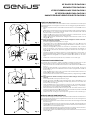
ISTRUZIONI MONTAGGIO KIT
Il “kit sblocco per FALCON K” permette di sbloccare il motoriduttore con la semplice
movimentazione di una maniglia con chiave. Per il montaggio seguire attentamen-
te le istruzioni:
1) Svitare completamente le due viti A e smontare lo sblocco a catena B come in
Fig.1.
2) Fissare il blocchetto fisso E al corpo riduttore tramite le viti C. Avvitare il registro
D nell rispettivo foro sul blocchetto E. Fissare le due estremità della molla F
tramite le viti C come illustrato in Fig.2.
3) Infilare il filo G come in Fig.3, prima nel foro del disco di azionamento, poi nel
registro di regolazione D ed in fine nella guaina H.
4) Fissare nella posizione desiderata la maniglia di azionamento tramite i fori di
fisaggio M, Fig.4.
Attenzione: Posizionare la maniglia in modo da non obbligare il cavo G a dei cam-
biamenti di direzione repentini.
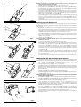
5) Avvitare il registro N nell’apposito foro, Fig.5.
6) Far scorrere tutto il cavo G nella guaina H, inserire poi il cavo G prima nel
registro N e poi nel blocchetto di fissaggio O. Mettere in tensione il cavo e
bloccarlo tramite la vite P, Fig.6.
7) Inserire la maniglia R sul quadro di comando e ruotandola, di 90° in senso
orario ed antiorario, per verificare il corretto funzionamento del sistema di
sblocco, Fig.7. Nel caso sia necessario regolare la tensione del cavo agire sui
registri N e D.
8) Portare la maniglia in posizione di sblocco, ruotandola di 90° in senso orario, e
sfilare la maniglia stessa. Posizionare il carter esterno Q e fissarlo con la vite S.
Riposizionare la maniglia R con la relativa rondella U e fissarla con la vite T,
Fig.8.
9) Posizionare il carter manopola I al corpo riduttore con le viti L, Fig.9.
KIT INSTALLATION INSTRUCTIONS
The “release kit for FALCON K” makes it possible to release the gearmotor by just
moving a handle with key. To install, carefully follow the instructions below:
1) Fully unscrew the two screws A and remove the chain release device B as shown
in Fig. 1.
2) Secure the fixed block E to the gearmotor body with screws C. Screw the
adjuster D in its hole on block E. Secure the two ends of spring F with screws C as
shown in Fig. 2.
3) Insert wire G as shown in Fig. 3, first in the hole of the activation disk, then into the
adjuster D and, lastly, in the sheath H.
4) Secure the activation handle in the required position by using the fixing holes M,
Fig 4.
Attention: Position the handle avoiding to impose sudden changes of direction to
cable G.
5) Screw adjuster N in the appropriate hole, Fig.5.
6) Thread the entire cable G through sheath H, then insert cable G first in the
adjuster N and then in the fastening block O. Apply tension to the cable and
secure it with screw P, Fig. 6.
7) Insert handle R on the control panel and, turning it by 90° clockwise and anti-
clockwise, check if the release system is operating correctly, Fig. 7. If necessary,
adjust tension of the cable with adjusters N and D.
8) Take the handle into release position, turning it by 90° clockwise, and remove it.
Position the external housing Q and secure it with screw S. Re-position handle R
with washer U and secure it with screw T, Fig.8.
9) Position the knob housing I on the body of the gearmotor with screws L, Fig.9.
INSTRUCTIONS DE MONTAGE DU KIT
Le “kit de déverrouillage pour FALCON K” permet de déverrouiller le motoréducteur
par un simple actionnement d'une poignée dotée d'une clé. Pour le montage suivre
attentivement les instructions:
1) Dévisser complètement les deux vis A et démonter le déverrouillage à chaîne B
d'après la Fig.1.
2) Fixer le bloc fixe E sur le corps du réducteur avec les vis C. Visser le dispositif de
réglage D dans le trou correspondant sur le bloc E. Fixer les deux extrémités du
ressort F avec les vis C d'après la Fig.2.
3) Introduire le fil G d'après la Fig.3, d'abord dans le trou du disque d'actionnement,
puis dans le dispositif de réglage D et enfin dans la gaine H.
4) Fixer dans la position souhaitée la poignée d'actionnement avec les trous de
fixation M, Fig.4.
La pagina si sta caricando...
-
 1
1
-
 2
2


Genius FALCON K Manuale del proprietario
- Tipo
- Manuale del proprietario
in altre lingue
- English: Genius FALCON K Owner's manual
- français: Genius FALCON K Le manuel du propriétaire
- español: Genius FALCON K El manual del propietario
- Deutsch: Genius FALCON K Bedienungsanleitung
Documenti correlati
-
Genius FALCON K Istruzioni per l'uso
-
-
Genius Falcon Manuale utente
-
-
-
Genius Falcon 14C Installation Instructions Manual
-
-
-
-
