Behringer MS-1-RD Guida Rapida
- Categoria
- Sintetizzatore
- Tipo
- Guida Rapida
Questo manuale è adatto anche per

Quick Start Guide
MS-1
Analog Synthesizer with 32 Full-Size Keys, 3340 VCO with
4 Simultaneous Waveforms, VCF, NovaMod FM Sources,
32-Step Sequencer, Arpeggiator and Live Performance Kit
V 4.0

2 MS-1 Quick Start Guide 3
Instrucciones de
seguridad
NEGACIÓN LEGAL
GARANTÍA LIMITADA
Las terminales marcadas con este símbolo
transportan corriente eléctrica de
magnitud suciente como para constituir
un riesgo de descarga eléctrica. Utilice solo cables de
altavoz profesionales y de alta calidad con conectores
TS de 6,3 mm o de bayoneta prejados. Cualquier otra
instalación o modicación debe ser realizada únicamente
por un técnico cualicado.
Este símbolo, siempre que aparece,
leadvierte de la presencia de voltaje
peligroso sin aislar dentro de la caja;
estevoltaje puede ser suciente para constituir un riesgo
dedescarga.
Este símbolo, siempre que aparece,
leadvierte sobre instrucciones operativas
y de mantenimiento que aparecen en la
documentación adjunta. Por favor, lea el manual.
Atención
Para reducir el riesgo de descarga
eléctrica, no quite la tapa (o la parte
posterior). No hay piezas en el interior del equipo que
puedan ser reparadas por el usuario. Si es necesario,
póngase en contacto con personal cualicado.
Atención
Para reducir el riesgo de incendio o
descarga eléctrica, no exponga este
aparato a la lluvia, humedad o alguna otra fuente que
pueda salpicar o derramar algún líquido sobre el aparato.
Nocoloque ningún tipo de recipiente para líquidos sobre
el aparato.
Atención
Las instrucciones de servicio deben
llevarlas a cabo exclusivamente personal
cualicado. Para evitar el riesgo de una descarga eléctrica,
no realice reparaciones que no se encuentren descritas
en el manual de operaciones. Lasreparaciones deben ser
realizadas exclusivamente por personalcualicado.
1. Lea las instrucciones.
2. Conserve estas instrucciones.
3. Preste atención a todas las advertencias.
4. Siga todas las instrucciones.
5. No use este aparato cerca del agua.
6. Limpie este aparato con un paño seco.
7. No bloquee las aberturas de ventilación. Instale el
equipo de acuerdo con las instrucciones del fabricante.
8. No instale este equipo cerca de fuentes de calor
tales como radiadores, acumuladores de calor, estufas u
otros aparatos (incluyendo amplicadores) que puedan
producir calor.
9. No elimine o deshabilite nunca la conexión a tierra
del aparato o del cable de alimentación de corriente.
Unenchufe polarizado tiene dos polos, uno de los cuales
tiene un contacto más ancho que el otro. Una clavija con
puesta a tierra dispone de tres contactos: dos polos y la
puesta a tierra. El contacto ancho y el tercer contacto,
respectivamente, son los que garantizan una mayor
seguridad. Si el enchufe suministrado con el equipo no
concuerda con la toma de corriente, consulte con un
electricista para cambiar la toma de corriente obsoleta.
10. Coloque el cable de suministro de energía de manera
que no pueda ser pisado y que esté protegido de objetos
alados. Asegúrese de que el cable de suministro de
energía esté protegido, especialmente en la zona de la
clavija y en el punto donde sale del aparato.
11. Use únicamente los dispositivos o accesorios
especicados por el fabricante.
12. Use únicamente la
carretilla, plataforma,
trípode, soporte o mesa
especicados por el
fabricante o suministrados
junto con el equipo.
Altransportar el equipo,
tenga cuidado para evitar
daños y caídas al tropezar con algún obstáculo.
13. Desenchufe el equipo durante tormentas o si no va a
utilizarlo durante un periodo largo.
14. Confíe las reparaciones únicamente a servicios
técnicos cualicados. La unidad requiere mantenimiento
siempre que haya sufrido algún daño, si el cable de
suministro de energía o el enchufe presentaran daños,
sehubiera derramado un líquido o hubieran caído objetos
dentro del equipo, si el aparato hubiera estado expuesto
a la humedad o la lluvia, si ha dejado de funcionar de
manera normal o si ha sufrido algún golpe o caída.
15. Al conectar la unidad a la toma de corriente eléctrica
asegúrese de que la conexión disponga de una unión
atierra.
16. Si el enchufe o conector de red sirve como único
medio de desconexión, éste debe ser accesiblefácilmente.
17. Cómo debe deshacerse de
este aparato: Este símbolo indica
que este aparato no debe ser
tratado como basura orgánica,
según lo indicado en la Directiva
WEEE (2012/19/EU) y a las
normativas aplicables en su país.
En lugar de ello deberá llevarlo al punto limpio más
cercano para el reciclaje de sus elementos eléctricos/
electrónicos (EEE). Al hacer esto estará ayudando a
prevenir las posibles consecuencias negativas para el
medio ambiente y la salud que podrían ser provocadas
por una gestión inadecuada de este tipo de aparatos.
Además, el reciclaje de materiales ayudará a conservar
los recursos naturales. Para más información acerca del
reciclaje de este aparato, póngase en contacto con el
Ayuntamiento de su ciudad o con el punto limpio local.
18. No instale esta unidad en un espacio muy reducido,
tal como encastrada en una librería o similar.
19. No coloque objetos con llama, como una vela
encendida, sobre este aparato.
20. Tenga presentes todas las advertencias relativas
al reciclaje y correcta eliminación de las pilas. Las pilas
deben ser siempre eliminadas en un punto limpio y nunca
con el resto de la basura orgánica.
21. Use este aparato en rangos de temperatura
moderados y/o tropicales.
Music Tribe no admite ningún tipo de responsabilidad
por cualquier daño o pérdida que pudiera sufrir
cualquier persona por conar total o parcialmente en
la descripciones, fotografías o armaciones contenidas
en este documento. Las especicaciones técnicas,
imágenes y otras informaciones contenidas en este
documento están sujetas a modicaciones sin previo
aviso. Todas las marcas comerciales que aparecen
aquí son propiedad de sus respectivos dueños. Midas,
Klark Teknik, Lab Gruppen, Lake, Tannoy, Turbosound,
TC Electronic, TC Helicon, Behringer, Bugera, Auratone y
Coolaudio son marcas comerciales o marcas registradas
de Music Tribe Global Brands Ltd. © Music Tribe Global
Brands Ltd. 2020 Reservados todos los derechos.
Si quiere conocer los detalles y condiciones aplicables
de la garantía así como información adicional sobre la
Garantía limitada de Music Tribe, consulte online toda la
información en la web musictribe.com/warranty.
Terminals marked with this symbol carry
electrical current of sucient magnitude
to constitute risk of electric shock.
Use only high-quality professional speaker cables with
¼" TS or twist-locking plugs pre-installed. Allother
installation or modication should be performed only
by qualiedpersonnel.
This symbol, wherever it appears,
alertsyou to the presence of uninsulated
dangerous voltage inside the
enclosure-voltage that may be sucient to constitute a
risk ofshock.
This symbol, wherever it appears,
alertsyou to important operating and
maintenance instructions in the
accompanying literature. Please read the manual.
Caution
To reduce the risk of electric shock, donot
remove the top cover (or the rear section).
No user serviceable parts inside. Refer servicing to
qualied personnel.
Caution
To reduce the risk of re or electric shock,
do not expose this appliance to rain and
moisture. The apparatus shall not be exposed to dripping
or splashing liquids and no objects lled with liquids,
suchas vases, shall be placed on the apparatus.
Caution
These service instructions are for use
by qualied service personnel only.
Toreduce the risk of electric shock do not perform any
servicing other than that contained in the operation
instructions. Repairs have to be performed by qualied
servicepersonnel.
1. Read these instructions.
2. Keep these instructions.
3. Heed all warnings.
4. Follow all instructions.
5. Do not use this apparatus near water.
6. Clean only with dry cloth.
7. Do not block any ventilation openings. Install in
accordance with the manufacturer’s instructions.
8. Do not install near any heat sources such as
radiators, heat registers, stoves, or other apparatus
(including ampliers) that produce heat.
9. Do not defeat the safety purpose of the polarized
or grounding-type plug. A polarized plug has two blades
with one wider than the other. A grounding-type plug
has two blades and a third grounding prong. The wide
blade or the third prong are provided for your safety. Ifthe
provided plug does not t into your outlet, consult an
electrician for replacement of the obsolete outlet.
10. Protect the power cord from being walked on or
pinched particularly at plugs, convenience receptacles,
and the point where they exit from the apparatus.
11. Use only attachments/accessories specied by
themanufacturer.
12. Use only with the
cart, stand, tripod, bracket,
or table specied by the
manufacturer, orsold with
the apparatus. When a cart
is used, use caution when
moving the cart/apparatus
combination to avoid
injury from tip-over.
13. Unplug this apparatus during lightning storms or
when unused for long periods of time.
14. Refer all servicing to qualied service personnel.
Servicing is required when the apparatus has been
damaged in any way, such as power supply cord or plug
is damaged, liquid has been spilled or objects have fallen
into the apparatus, the apparatus has been exposed
to rain or moisture, does not operate normally, or has
beendropped.
15. The apparatus shall be connected to a MAINS socket
outlet with a protective earthing connection.
16. Where the MAINS plug or an appliance coupler is
used as the disconnect device, the disconnect device shall
remain readily operable.
17. Correct disposal of this
product: This symbol indicates
that this product must not be
disposed of with household
waste, according to the WEEE
Directive (2012/19/EU) and
your national law. This product
should be taken to a collection center licensed for the
recycling of waste electrical and electronic equipment
(EEE). The mishandling of this type of waste could have
a possible negative impact on the environment and
human health due to potentially hazardous substances
that are generally associated with EEE. At the same time,
your cooperation in the correct disposal of this product
will contribute to the ecient use of natural resources.
For more information about where you can take your
waste equipment for recycling, please contact your local
city oce, or your household waste collection service.
18. Do not install in a conned space, such as a book
case or similar unit.
19. Do not place naked ame sources, such as lighted
candles, on the apparatus.
20. Please keep the environmental aspects of battery
disposal in mind. Batteries must be disposed-of at a
battery collection point.
21. Use this apparatus in tropical and/or
moderate climates.
Music Tribe accepts no liability for any loss which
may be suered by any person who relies either
wholly or in part upon any description, photograph,
or statement contained herein. Technical specications,
appearances and other information are subject to
change without notice. All trademarks are the property
of their respective owners. Midas, Klark Teknik,
Lab Gruppen, Lake, Tannoy, Turbosound, TC Electronic,
TC Helicon, Behringer, Bugera, Auratone and Coolaudio
are trademarks or registered trademarks of Music
Tribe Global Brands Ltd. © Music Tribe Global Brands
Ltd. 2020 All rights reserved.
For the applicable warranty terms and conditions
and additional information regarding Music Tribe’s
Limited Warranty, please see complete details online at
musictribe.com/warranty.
Important Safety
Instructions
LEGAL DISCLAIMER
LIMITED WARRANTY

4 MS-1 Quick Start Guide 5
Consignes de sécurité
DÉNI LÉGAL
GARANTIE LIMITÉE
Wichtige
Sicherheitshinweise
HAFTUNGSAUSSCHLUSS
BESCHRÄNKTE GARANTIE
Les points repérés par ce symbole portent
une tension électrique susante pour
constituer un risque d’électrocution.
Utilisez uniquement des câbles d’enceintes professionnels
de haute qualité avec ches Jack mono 6,35 mm ou ches
à verrouillages déjà installées. Touteautre installation ou
modication doit être eectuée uniquement par un
personnel qualié.
Ce symbole avertit de la présence d’une
tension dangereuse et non isolée à
l’intérieur de l’appareil - elle peut
provoquer des chocs électriques.
Attention
Ce symbol signale les consignes
d’utilisation et d’entre ! Tien importantes
dans la documentation fournie. Lisez les consignes de
sécurité du manuel d’utilisation de l’appareil.
Attention
Pour éviter tout risque de choc électrique,
ne pas ouvrir le capot de l’appareil ni
démonter le panneau arrière. L’intérieur de l’appareil
ne possède aucun élément réparable par l’utilisateur.
Laissertoute réparation à un professionnel qualié.
Attention
Pour réduire les risques de feu et de choc
électrique, n’exposez pas cet appareil à la
pluie, à la moisissure, aux gouttes ou aux éclaboussures.
Ne posez pas de récipient contenant un liquide sur
l’appareil (un vase par exemple).
Attention
Ces consignes de sécurité et d’entretien
sont destinées à un personnel qualié.
Pouréviter tout risque de choc électrique, n’eectuez
aucune réparation sur l’appareil qui ne soit décrite par le
manuel d’utilisation. Les éventuelles réparations doivent
être eectuées uniquement par un technicien spécialisé.
1. Lisez ces consignes.
2. Conservez ces consignes.
3. Respectez tous les avertissements.
4. Respectez toutes les consignes d’utilisation.
5. N’utilisez jamais l’appareil à proximité d’un liquide.
6. Nettoyez l’appareil avec un chion sec.
7. Veillez à ne pas empêcher la bonne ventilation
de l’appareil via ses ouïes de ventilation. Respectezles
consignes du fabricant concernant l’installation
del’appareil.
8. Ne placez pas l’appareil à proximité d’une source
de chaleur telle qu’un chauage, une cuisinière ou tout
appareil dégageant de la chaleur (y compris un ampli
depuissance).
9. Ne supprimez jamais la sécurité des prises bipolaires
ou des prises terre. Les prises bipolaires possèdent deux
contacts de largeur diérente. Leplus large est le contact
de sécurité. Les prises terre possèdent deux contacts plus
une mise à la terre servant de sécurité. Si la prise du bloc
d’alimentation ou du cordon d’ali-mentation fourni ne
correspond pas à celles de votre installation électrique,
faites appel à un électricien pour eectuer le changement
de prise.
10. Installez le cordon d’alimentation de telle façon
que personne ne puisse marcher dessus et qu’il soit
protégé d’arêtes coupantes. Assurez-vous que le cordon
d’alimentation est sufsamment protégé, notamment au
niveau de sa prise électrique et de l’endroit où il est relié à
l’appareil; cela est également valable pour une éventuelle
rallonge électrique.
11. Utilisez exclusivement des accessoires et des
appareils supplémentaires recommandés par lefabricant.
12. Utilisez
exclusivement des
chariots, des diables,
desprésentoirs, despieds
et des surfaces de
travail recommandés
par le fabricant ou
livrés avec le produit.
Déplacezprécautionneusement tout chariot ou diable
chargé pour éviter d’éventuelles blessures en cas dechute.
13. Débranchez l’appareil de la tension secteur en cas
d’orage ou si l’appareil reste inutilisé pendant une longue
période de temps.
14. Les travaux d’entretien de l’appareil doivent
être eectués uniquement par du personnel qualié.
Aucunentretien n’est nécessaire sauf si l’appareil est
endommagé de quelque façon que ce soit (dommagessur
le cordon d’alimentation ou la prise par exemple), siun
liquide ou un objet a pénétré à l’intérieur du châssis, si
l’appareil a été exposé à la pluie ou à l’humidité, s’il ne
fonctionne pas correctement ou à la suite d’une chute.
15. L’appareil doit être connecté à une prise secteur
dotée d’une protection par mise à la terre.
16. La prise électrique ou la prise IEC de tout appareil
dénué de bouton marche/arrêt doit rester accessible
enpermanence.
17. Mise au rebut appropriée de
ce produit: Ce symbole indique
qu’en accord avec la directive DEEE
(2012/19/EU) et les lois en vigueur
dans votre pays, ce produit ne
doit pas être jeté avec les déchets
ménagers. Ce produit doit être
déposé dans un point de collecte agréé pour le recyclage
des déchets d’équipements électriques et électroniques
(EEE). Une mauvaise manipulation de ce type de déchets
pourrait avoir un impact négatif sur l’environnement
et la santé à cause des substances potentiellement
dangereuses généralement associées à ces équipements.
En même temps, votre coopération dans la mise au
rebut de ce produit contribuera à l’utilisation ecace
des ressources naturelles. Pour plus d’informations
sur l’endroit où vous pouvez déposer vos déchets
d’équipements pour le recyclage, veuillez contacter votre
mairie ou votre centre local de collecte des déchets.
18. N’installez pas l’appareil dans un espace conné tel
qu’une bibliothèque ou meuble similaire.
19. Ne placez jamais d’objets enammés, tels que des
bougies allumées, sur l’appareil.
20. Gardez à l’esprit l’impact environnemental lorsque
vous mettez des piles au rebus. Les piles usées doivent
être déposées dans un point de collecte adapté.
21. Utilisez l’appareil dans un climat tropical
et/ou modéré.
Music Tribe ne peut être tenu pour responsable pour
toute perte pouvant être subie par toute personne
se ant en partie ou en totalité à toute description,
photographie ou armation contenue dans ce
document. Les caractéristiques, l’apparence et d’autres
informations peuvent faire l’objet de modications
sans notication. Toutes les marques appartiennent
à leurs propriétaires respectifs. Midas, Klark Teknik,
Lab Gruppen, Lake, Tannoy, Turbosound, TC Electronic,
TC Helicon, Behringer, Bugera, Auratone et Coolaudio
sont des marques ou marques déposées de Music Tribe
Global Brands Ltd. © Music Tribe Global Brands Ltd.
2020 Tous droits réservés.
Pour connaître les termes et conditions de garantie
applicables, ainsi que les informations supplémentaires
et détaillées sur la Garantie Limitée de Music Tribe,
consultez le site Internet musictribe.com/warranty.
Vorsicht
Die mit dem Symbol markierten
Anschlüsse führen so viel Spannung,
dassdie Gefahr eines Stromschlags besteht.
Verwenden Sie nur hochwertige, professionelle
Lautsprecherkabel mit vorinstallierten 6,35 mm
MONO-Klinkensteckern oder Lautsprecherstecker
mit Drehverriegelung. Alle anderen Installationen
oder Modikationen sollten nur von qualiziertem
Fachpersonal ausgeführt werden.
Achtung
Um eine Gefährdung durch Stromschlag
auszuschließen, darf die Geräteabdeckung
bzw. Geräterückwand nicht abgenommen werden.
ImInnern des Geräts benden sich keine vom Benutzer
reparierbaren Teile. Reparaturarbeiten dürfen nur von
qualiziertem Personal ausgeführt werden.
Achtung
Um eine Gefährdung durch Feuer bzw.
Stromschlag auszuschließen, darf dieses
Gerät weder Regen oder Feuchtigkeit ausgesetzt werden
noch sollten Spritzwasser oder tropfende Flüssigkeiten
in das Gerät gelangen können. Stellen Sie keine mit
Flüssigkeit gefüllten Gegenstände, wie z. B. Vasen,
aufdasGerät.
Achtung
Die Service-Hinweise sind nur durch
qualiziertes Personal zu befolgen.
Umeine Gefährdung durch Stromschlag zu vermeiden,
führen Sie bitte keinerlei Reparaturen an dem Gerät
durch, die nicht in der Bedienungsanleitung beschrieben
sind. Reparaturen sind nur von qualiziertem
Fachpersonaldurchzuführen.
1. Lesen Sie diese Hinweise.
2. Bewahren Sie diese Hinweise auf.
3. Beachten Sie alle Warnhinweise.
4. Befolgen Sie alle Bedienungshinweise.
5. Betreiben Sie das Gerät nicht in der Nähe vonWasser.
6. Reinigen Sie das Gerät mit einem trockenen Tuch.
7. Blockieren Sie nicht die Belüftungsschlitze. Beachten
Sie beim Einbau des Gerätes die Herstellerhinweise.
8. Stellen Sie das Gerät nicht in der Nähe von
Wärmequellen auf. Solche Wärmequellen sind z. B.
Heizkörper, Herde oder andere Wärme erzeugende Geräte
(auch Verstärker).
9. Entfernen Sie in keinem Fall die
Sicherheitsvorrichtung von Zweipol- oder geerdeten
Steckern. Ein Zweipolstecker hat zwei unterschiedlich
breite Steckkontakte. Ein geerdeter Stecker hat zwei
Steckkontakte und einen dritten Erdungskontakt.
Derbreitere Steckkontakt oder der zusätzliche
Erdungskontakt dient Ihrer Sicherheit. Falls das
mitgelieferte Steckerformat nicht zu Ihrer Steckdose
passt, wenden Sie sich bitte an einen Elektriker, damit die
Steckdose entsprechend ausgetauscht wird.
10. Verlegen Sie das Netzkabel so, dass es vor
Tritten und scharfen Kanten geschützt ist und nicht
beschädigt werden kann. Achten Sie bitte insbesondere
im Bereich der Stecker, Verlängerungskabel und an
der Stelle, an der das Netzkabel das Gerät verlässt,
aufausreichendenSchutz.
11. Das Gerät muss jederzeit mit intaktem Schutzleiter
an das Stromnetz angeschlossen sein.
12. Sollte der Hauptnetzstecker oder eine
Gerätesteckdose die Funktionseinheit zum Abschalten
sein, muss diese immer zugänglich sein.
13. Verwenden Sie nur Zusatzgeräte/Zubehörteile,
dielaut Hersteller geeignet sind.
14. Verwenden
Sie nur Wagen,
Standvorrichtungen,
Stative, Halter oder Tische,
die vom Hersteller benannt
oder im Lieferumfang
des Geräts enthalten
sind. Falls Sie einen
Wagen benutzen, seien Sie vorsichtig beim Bewegen
der Wagen- Gerätkombination, umVerletzungen durch
Stolpern zuvermeiden.
15. Ziehen Sie den Netzstecker bei Gewitter oder wenn
Sie das Gerät längere Zeit nicht benutzen.
16. Lassen Sie alle Wartungsarbeiten nur von
qualiziertem Service-Personal ausführen. EineWartung
ist notwendig, wenn das Gerät in irgendeiner Weise
beschädigt wurde (z. B. Beschädigung des Netzkabels oder
Steckers), Gegenstände oder Flüssigkeit in das Geräteinnere
gelangt sind, das Gerät Regen oder Feuchtigkeit ausgesetzt
wurde, das Gerät nicht ordnungsgemäß funktioniert oder
auf den Boden gefallen ist.
17. Korrekte Entsorgung
dieses Produkts: Dieses
Symbol weist darauf hin, das
Produkt entsprechend der
WEEE Direktive (2012/19/EU)
und der jeweiligen nationalen
Gesetze nicht zusammen mit
Ihren Haushaltsabfällen zu entsorgen. DiesesProdukt
sollte bei einer autorisierten Sammelstelle für
Recycling elektrischer und elektronischer Geräte (EEE)
abgegeben werden. Wegen bedenklicher Substanzen,
diegenerell mit elektrischen und elektronischen Geräten
in Verbindung stehen, könnte eine unsachgemäße
Behandlung dieser Abfallart eine negative Auswirkung
auf Umwelt und Gesundheit haben. Gleichzeitig
gewährleistet Ihr Beitrag zur richtigen Entsorgung dieses
Produkts die eektive Nutzung natürlicher Ressourcen.
Fürweitere Informationen zur Entsorgung Ihrer Geräte
bei einer Recycling-Stelle nehmen Sie bitte Kontakt zum
zuständigen städtischen Büro, Entsorgungsamt oder zu
Ihrem Haushaltsabfallentsorgerauf.
18. Installieren Sie das Gerät nicht in einer beengten
Umgebung, zum Beispiel Bücherregal oder ähnliches.
19. Stellen Sie keine Gegenstände mit oenen
Flammen, etwa brennende Kerzen, auf das Gerät.
20. Beachten Sie bei der Entsorgung von Batterien
den Umweltschutz-Aspekt. Batterien müssen bei einer
Batterie-Sammelstelle entsorgt werden.
21. Verwenden Sie das Gerät in tropischen und/oder
gemäßigten Klimazonen.
Music Tribe übernimmt keine Haftung für Verluste,
die Personen entstanden sind, die sich ganz oder
teilweise auf hier enthaltene Beschreibungen,
Fotos oder Aussagen verlassen haben. Technische Daten,
Erscheinungsbild und andere Informationen können
ohne vorherige Ankündigung geändert werden. Alle
Warenzeichen sind Eigentum der jeweiligen Inhaber.
Midas, Klark Teknik, Lab Gruppen, Lake, Tannoy,
Turbosound, TC Electronic, TC Helicon, Behringer,
Bugera, Auratone und Coolaudio sind Warenzeichen
oder eingetragene Warenzeichen der Music Tribe Global
Brands Ltd. © Music Tribe Global Brands Ltd. 2020 Alle
Rechte vorbehalten.
Die geltenden Garantiebedingungen und zusätzliche
Informationen bezüglich der von Music Tribe gewährten
beschränkten Garantie nden Sie online unter
musictribe.com/warranty.

6 MS-1 Quick Start Guide 7
Instruções de Segurança
Importantes
LEGAL RENUNCIANTE
Aviso!
Terminais marcados com o símbolo
carregam corrente elétrica de magnitude
suciente para constituir um risco de choque elétrico.
Use apenas cabos de alto-falantes de alta qualidade
com plugues TS de ¼" ou plugues com trava de torção
pré-instalados. Todas as outras instalações e modicações
devem ser efetuadas por pessoasqualicadas.
Este símbolo, onde quer que o encontre,
alerta-o para a leitura das instruções de
manuseamento que acompanham o
equipamento. Por favor leia o manual de instruções.
Atenção
De forma a diminuir o risco de choque
eléctrico, não remover a cobertura
(ouasecção de trás). Não existem peças substituíveis por
parte do utilizador no seu interior. Para esse efeito recorrer
a um técnico qualicado.
Atenção
Para reduzir o risco de incêndios ou
choques eléctricos o aparelho não deve ser
exposto à chuva nem à humidade. Além disso, não deve
ser sujeito a salpicos, nem devem ser colocados em cima
do aparelho objectos contendo líquidos, tais como jarras.
Atenção
Estas instruções de operação devem ser
utilizadas, em exclusivo, por técnicos de
assistência qualicados. Para evitar choques eléctricos
não proceda a reparações ou intervenções, que não as
indicadas nas instruções de operação, salvo se possuir as
quali-cações necessárias. Para evitar choques eléctricos
não proceda a reparações ou intervenções, que não as
indicadas nas instruções de operação. Só o deverá fazer se
possuir as qualicações necessárias.
1. Leia estas instruções.
2. Guarde estas instruções.
3. Preste atenção a todos os avisos.
4. Siga todas as instruções.
5. Não utilize este dispositivo perto de água.
6. Limpe apenas com um pano seco.
7. Não obstrua as entradas de ventilação. Instale de
acordo com as instruções do fabricante.
8. Não instale perto de quaisquer fontes de calor tais
como radiadores, bocas de ar quente, fogões de sala
ou outros aparelhos (incluindo amplicadores) que
produzam calor.
9. Não anule o objectivo de segurança das chas
polarizadas ou do tipo de ligação à terra. Uma cha
polarizada dispõe de duas palhetas sendo uma mais larga
do que a outra. Uma cha do tipo ligação à terra dispõe
de duas palhetas e um terceiro dente de ligação à terra.
A palheta larga ou o terceiro dente são fornecidos para
sua segurança. Se a cha fornecida não encaixar na sua
tomada, consulte um electricista para a substituição da
tomada obsoleta.
10. Proteja o cabo de alimentação de pisadelas ou
apertos, especialmente nas chas, extensões, e no local
de saída da unidade. Certique-se de que o cabo eléctrico
está protegido. Verique particularmente nas chas, nos
receptáculos e no ponto em que o cabo sai doaparelho.
11. O aparelho tem de estar sempre conectado à rede
eléctrica com o condutor de protecção intacto.
12. Se utilizar uma cha de rede principal ou uma
tomada de aparelhos para desligar a unidade de
funcionamento, esta deve estar sempre acessível.
13. Utilize apenas ligações/acessórios especicados
pelofabricante.
14. Utilize apenas com
o carrinho, estrutura,
tripé, suporte, ou mesa
especicados pelo
fabricante ou vendidos
com o dispositivo.
Quandoutilizar um
carrinho, tenha cuidado ao
mover o conjunto carrinho/dispositivo para evitar danos
provocados pela terpidação.
15. Desligue este dispositivo durante as trovoadas
ou quando não for utilizado durante longos períodos
detempo.
16. Qualquer tipo de reparação deve ser sempre
efectuado por pessoal qualicado. É necessária uma
reparação sempre que a unidade tiver sido de alguma
forma danicada, como por exemplo: no caso do cabo
de alimentação ou cha se encontrarem danicados;
naeventualidade de líquido ter sido derramado ou
objectos terem caído para dentro do dispositivo; no caso
da unidade ter estado exposta à chuva ou à humidade;
seesta não funcionar normalmente, ou se tiver caído.
17. Correcta eliminação deste
produto: este símbolo indica que
o produto não deve ser eliminado
juntamente com os resíduos
domésticos, segundo a Directiva
REEE (2012/19/EU) e a legislação
nacional. Este produto deverá
ser levado para um centro de recolha licenciado para a
reciclagem de resíduos de equipamentos eléctricos e
electrónicos (EEE). O tratamento incorrecto deste tipo
de resíduos pode ter um eventual impacto negativo
no ambiente e na saúde humana devido a substâncias
potencialmente perigosas que estão geralmente
associadas aos EEE. Ao mesmo tempo, a sua colaboração
para a eliminação correcta deste produto irá contribuir
para a utilização eciente dos recursos naturais. Paramais
informação acerca dos locais onde poderá deixar o seu
equipamento usado para reciclagem, é favor contactar
os serviços municipais locais, a entidade de gestão de
resíduos ou os serviços de recolha de resíduosdomésticos.
18. Não instale em lugares connados, tais como
estantes ou unidades similares.
19. Não coloque fontes de chama, tais como velas
acesas, sobre o aparelho.
20. Favor, obedecer os aspectos ambientais de descarte
de bateria. Baterias devem ser descartadas em um ponto
de coletas de baterias.
21. Use este aparelho em climas tropicais e/
ou moderados.
O Music Tribe não se responsabiliza por perda alguma
que possa ser sofrida por qualquer pessoa que dependa,
seja de maneira completa ou parcial, de qualquer
descrição, fotograa, ou declaração aqui contidas.
Dados técnicos, aparências e outras informações estão
sujeitas a modicações sem aviso prévio. Todas as
marcas são propriedade de seus respectivos donos.
Midas, Klark Teknik, Lab Gruppen, Lake, Tannoy,
Turbosound, TC Electronic, TC Helicon, Behringer, Bugera,
Auratone e Coolaudio são marcas ou marcas registradas
do Music Tribe Global Brands Ltd. © Music Tribe Global
Brands Ltd. 2020 Todos direitos reservados.
Para obter os termos de garantia aplicáveis e condições e
informações adicionais a respeito da garantia limitada do
Music Tribe, favor vericar detalhes na íntegra através do
website musictribe.com/warranty.
LEGAL RENUNCIANTE
GARANTIA LIMITADA
Attenzione
I terminali contrassegnati da questo
simbolo conducono una corrente elettrica
di magnitudine suciente a costituire un rischio di scossa
elettrica. Utilizzare solo cavi per altoparlanti professionali
di alta qualità con jack sbilanciati da 6,35mm. o connettori
con blocco a rotazione. Tutte le altre installazioni o
modiche devono essere eseguite esclusivamente da
personale qualicato.
Attenzione
Questo simbolo, ovunque appaia, avverte
della presenza di una tensione pericolosa
non isolata all'interno dello chassis, tensione che può
essere suciente per costituire un rischio di scossa
elettrica.
Attenzione
Questo simbolo, ovunque appaia, segnala
importanti istruzioni operative e di
manutenzione nella documentazione allegata. Si invita a
leggere il manuale.
Attenzione
Per ridurre il rischio di scosse elettriche,
non rimuovere il coperchio superiore
(o la sezione posteriore). All'interno non ci sono parti
riparabili dall'utente. Per la manutenzione rivolgersi a
personale qualicato.
Attenzione
Per ridurre il rischio di incendi o scosse
elettriche, non esporre questo apparecchio
a pioggia e umidità. L'apparecchio non deve essere
esposto a gocciolio o schizzi di liquidi e nessun oggetto
contenente liquidi, come vasi, deve essere collocato
sull'apparecchio.
Attenzione
Queste istruzioni di servizio sono destinate
esclusivamente a personale qualicato.
Per ridurre il rischio di scosse elettriche non eseguire
interventi di manutenzione diversi da quelli contenuti
nel manuale di istruzioni. Le riparazioni devono essere
eseguite da personale di assistenza qualicato.
1. Leggere queste istruzioni.
2. Conservare queste istruzioni.
3. Prestare attenzione a tutti gli avvisi.
4. Applicare tutte le istruzioni.
5. Non utilizzare questo dispositivo vicino l'acqua.
6. Pulire esclusivamente con un panno asciutto.
7. Non bloccare le aperture di ventilazione. Installare in
conformità con le istruzioni del produttore.
8. Non installare vicino a fonti di calore come
radiatori, termoregolatori, stufe o altri apparecchi
(inclusi amplicatori) che producono calore.
9. Non escludere la sicurezza fornita dalla spina
polarizzata o con messa a terra. Una spina polarizzata ha
due lame, una più larga dell'altra. Una spina con messa a
terra ha due lame e un terzo polo di messa a terra. La lama
larga o il terzo polo sono forniti per la vostra sicurezza.
Se la spina fornita non si adatta alla presa, consultare un
elettricista per la sostituzione della presa obsoleta.
10. Proteggere il cavo di alimentazione dal calpestio
o essere schiacciato in particolare alle spine, prese di
corrente e il punto in cui esce dall'apparecchio.
11. Utilizzare esclusivamente dispositivi/accessori
specicati dal produttore.
12. Utilizzare solo
carrelli, supporti, treppiedi,
stae o tavoli indicati dal
produttore o venduti con
l'apparecchio. Utilizzando
un carrello, prestare
attenzione quando si
sposta la combinazione
carrello/apparecchio per evitare lesioni dovute al
ribaltamento.
13. Scollegare questo apparecchio durante i temporali o
se non è utilizzato per lunghi periodi di tempo.
14. Per tutte le riparazioni rivolgersi a personale
qualicato. La manutenzione è necessaria quando
l'apparecchio è danneggiato in qualsiasi modo, come
danneggiamento del cavo di alimentazione o della spina,
versamento di liquido o oggetti caduti nell'apparecchio,
se l'apparecchio è stato esposto a pioggia o umidità, se
non funziona normalmente o è caduto.
15. L'apparecchio deve essere collegato a una presa di
corrente elettrica con messa a terra di protezione.
16. Se la spina o una presa del dispositivo è utilizzata
come dispositivo di disconnessione, deve essere
facilmente utilizzabile.
17. Smaltimento corretto di
questo prodotto: questo simbolo
indica che questo dispositivo non
deve essere smaltito insieme
ai riuti domestici, secondo
la Direttiva RAEE (2012/19 /
UE) e la vostra legislazione
nazionale. Questo prodotto deve essere portato in un
centro di raccolta autorizzato per il riciclaggio di riuti
di apparecchiature elettriche ed elettroniche (RAEE).
La cattiva gestione di questo tipo di riuti potrebbe avere
un possibile impatto negativo sull'ambiente e sulla salute
umana a causa di sostanze potenzialmente pericolose
che sono generalmente associate alle apparecchiature
elettriche ed elettroniche. Nello stesso tempo la vostra
collaborazione al corretto smaltimento di questo prodotto
contribuirà all'utilizzo eciente delle risorse naturali. Per
ulteriori informazioni su dove è possibile trasportare le
apparecchiature per il riciclaggio vi invitiamo a contattare
l'ucio comunale locale o il servizio di raccolta dei
riuti domestici.
18. Non installare in uno spazio ristretto, come in una
libreria o in una struttura simile.
19. Non collocare sul dispositivo fonti di amme libere,
come candele accese.
20. Per lo smaltimento delle batterie, tenere in
considerazione gli aspetti ambientali. Le batterie devono
essere smaltite in un punto di raccolta delle batterie
esauste.
21. Utilizzare questo apparecchio in climi tropicali
e/o moderati.
Music Tribe non si assume alcuna responsabilità per
eventuali danni che possono essere subiti da chiunque
si adi in tutto o in parte a qualsiasi descrizione,
fotograa o dichiarazione contenuta qui. Speciche
tecniche, aspetti e altre informazioni sono soggette
a modiche senza preavviso. Tutti i marchi sono di
proprietà dei rispettivi titolari. Midas, Klark Teknik,
Lab Gruppen, Lake, Tannoy, Turbosound, TC Electronic,
TC Helicon, Behringer, Bugera, Auratone e Coolaudio
sono marchi o marchi registrati di Music Tribe
Global Brands Ltd. © Music Tribe Global Brands Ltd.
2020 Tutti i diritti riservati .
Per i termini e le condizioni di garanzia applicabili e le
informazioni aggiuntive relative alla garanzia limitata
di Music Tribe, consultare online i dettagli completi su
musictribe.com/warranty.
Informazioni importanti
DISCLAIMER LEGALE
GARANZIA LIMITATA
LEGAL RENUNCIANTE
GARANTIA LIMITADA

8 MS-1 Quick Start Guide 9
MS-1 Hook-up
(EN)
Step 1: Hook-Up
(ES)
Paso 1: Conexión
(FR)
Etape 1 : Connexions
(DE)
Schritt 1: Verkabelung
(PT)
Passo 1: Conexões
Headphones
Desktop Computer
MIDI Controller
Studio Monitors
Audio Interface
USB
USB
USB
USB
Supplied Power
Adapter
Headphones
Hold
Footswitch
Supplied Power
Adapter
(EN) Studio System
(ES) Sistema para estudio de grabación
(FR) Système de studio
(DE) Studio-System
(PT) Sistema de Estúdio
(EN) Band / Practice System
(ES) Sistema para un grupo/ensayos
(FR) Système pour répétition
(DE) Band/Proberaum-System
(PT) Sistema Banda/Prática

10 MS-1 Quick Start Guide 11
MS-1 Hook-up
Headphones
Mixing console
Active Loudspeakers
Laptop Computer
Hold
Footswitch
Supplied Power
Adapter
Supplied Power
Adapter
Hold
Footswitch
Headphones
MIDI IN
BEHRINGER MODEL D Analog Synthesizer
Analog
Line-Level
Output
MIDI OUT
(EN) Live System
(ES) Sistema para actuación en directo
(FR) Système pour représentation
(DE) Live-System
(PT) Sistema Ao Vivo
(EN) System with an External Synthesizer
(ES) Sistema con sintetizador externo
(FR) Système avec synthétiseur externe
(DE) System mit externem Synthesizer
(PT) Sistema com sintetizador externo

12 MS-1 Quick Start Guide 13
(1)
(2) (4) (6) (7) (8) (9) (10) (11) (12) (13) (14) (15) (16) (17)
(3) (5)
(23)
(31) (32) (18) (19) (20) (21) (22) (25) (26) (27) (28) (29) (30)
(35)
(36)
(37)
(33)
(34)
(38)
(24)
(SEQUENCER)
(39) (40) (42) (44) (46) (47) (48) (49) (50) (51)
(41) (43) (45)
(54)
(53)
(58)
(52)
(56)
(55)
(57)
Top Panel Rear Panel
Live Performance Kit
MS-1 Controls

14 MS-1 Quick Start Guide 15
MS-1 Controls
(EN)
Step 2: Controls
(1) KEYBOARD – the keyboard has 32 semi-
weighted, full-size keys.
(2) TUNE – adjust the frequency of the main VCO
of the synthesizer.
(3) POWER – turn the synthesizer on or o. Make
sure all the connections are made before
turning on the unit. The LED shows when
power is applied and the unit is turned on.
Modulator Section
(4) LFO/CLK RATE – adjust the frequency of
the modulation LFO. The LED blinks at the
current rate.
(5) LFO RATE – select the frequency range of the
LFO rate fader from Low, Medium, or High.
(6) WAVEFORM – select the waveform from
triangular, square wave, random, or noise.
VCO Section
(7) MOD DEPTH – adjust the level of modulation
of the VCO.
(8) RANGE – select the overall frequency range
(octave) of the VCO from 16’, 8’, 4’, and 2’.
(9) PULSE WIDTH – adjust the pulse width of the
VCO when the pulse modulation source switch
is set to Manual. For LFO and ENV, it adjusts
the eect of the modulation.
(10) PULSE WIDTH MODULATION SOURCE–
select from LFO triangular waveform, Manual,
or Envelope.
Source Mixer Section
(11) PULSE – adjust the level of the
pulse waveform.
(12) SAW WAVE – adjust the level of the
sawtooth waveform.
(13) TRIANGULAR – adjust the level of the
triangular waveform.
(14) SUB OSCILLATOR – adjust the level of the
sub oscillator.
(15) SUB OSC TYPE – select the type of sub
oscillator, from 1 octave down, 2 octaves
down, or a narrower pulse width at 2
octaves down.
(16) NOISE – adjust the level of noise.
(17) EXT AUDIO – adjust the level of incoming
audio from an external source.
Sequencer Section
SEQUENCER – see details on page 16 and 36.
VCF Section
(18) FREQ – adjust the cuto frequency of the VCF.
Frequencies above the cuto are attenuated.
(19) RES – adjusts the amount of volume
level boost (resonance) given at the
cut-o frequency.
(20) ENV – adjust the amount of eect the
envelope has on the VCF.
(21) MOD – adjust the amount of eect the
modulation has on the VCF.
(22) KYBD – adjust the amount of eect the
keyboard has on the VCF.
(23) FM SOURCE – select the source of FM
modulation on the VCF from: pulse, sawtooth,
1 octave down square wave, 2 octaves down
square wave, 2 octaves down pulse, and noise.
(24) FM AMOUNT – adjust the eect of FM
modulation on the VCF.
VCA Section
(25) ENV/GATE – select if the VCA is aected by
the envelope controls, or by gate.
Envelope Section
When applied to the VCA, the ADSR envelope is used
to control the level of the note being played over
time. When applied to the VCF, the ADSR envelope
is used to control the cut-o frequency of the
lter for each note played over time. In addition,
the ADSR envelope can also aect the VCO pulse
width modulation.
Note that the ATTACK, DECAY and RELEASE stages are
measured in units of time, and the SUSTAIN stage is
measured in units of level.
(26) GATE + TRIG – a new envelope is triggered at
each key press.
GATE – when a new note is pressed, a new
envelope is trigged after the current one
is done.
LFO – the envelope is triggered by the LFO.
(27) A-ATTACK – this adjusts the time for the level
to reach maximum after a key is pressed.
(28) D-DECAY – this adjusts the time to decay
down to the SUSTAIN level after the attack
time is over.
(29) S-SUSTAIN – this sets the sustain level
reached after the attack and decay time
are over.
(30) R-RELEASE – this adjusts the time it takes for
the signal to decay once the key is released.
Control Section
(31) VOLUME – adjust the volume level of the
main output and headphones output. Turn
this down before turning the power on, or
before putting on headphones.
(32) GLIDE – adjust the amount of Glide time
(Portamento) between notes on the keyboard.
(33) GLIDE ON/OFF – turn the GLIDE on or o.
(34) TRANSPOSE – adjust the keyboard in one
octave steps, from Low, Medium, and High.
(35) VCO FADER – adjust the eect of the bender
controls on the VCO.
(36) VCF FADER – adjust the eect of the bender
controls on the VCF.
(37) LFO MOD FADER – adjust the amount of LFO
modulation added when the MOD switch
on the grip is pressed, or the BENDER (38) is
moved up.
(38) BENDER – move left or right to adjust the
frequency of the VCO and/or the cut-o
frequency of the VCF. The level of the eect
depends on the setting of the nearby VCO and
VCF faders. Move it up to add LFO modulation.
The modulation eect depends upon the
setting of the LFO MOD fader and other
LFO controls.
Rear Panel
(39) DC INPUT – connect the supplied DC
power adapter here. The power adapter
can be plugged into an AC outlet capable of
supplying from 100V to 240V at 50 Hz/60 Hz.
Use only the power adapter supplied.
(40) MAIN OUTPUT – connect this output to
the line-level inputs of mixers, keyboard
ampliers, or powered speakers for example.
(41) PHONES – connect your headphones to this
output. Make sure the volume is turned down
before putting on headphones.
(42) EXT AUDIO INPUT – this input can be
connected to the line level audio output from
an external audio device. Adjust the level
using the EXT AUDIO fader in the SOURCE
MIXER section.
(43) HOLD – an optional footswitch can be
connected here, to hold or release any
pattern playing in the Sequencer, and in
normal performance.
(44) VCF CV INPUT – the VCF can be controlled by
an external control voltage connected here.
(45) EXT CLK INPUT – an external clock signal can
be applied here.
(46) CV/GATE INPUT – these inputs allow the
connection of control voltage and gate signals
from compatible external devices such as
modular synthesizer equipment.
(47) CV/GATE OUTPUT – these outputs allow
the connection of control voltage and gate
signals to compatible external devices such as
modular synthesizer equipment.
(48) VELOCITY OUT – outputs a variable control
voltage based on the key velocity.
(49) MIDI Connections – these 3 standard 5-pin
DIN Jacks allow connections to other MIDI
equipment in your system.
MIDI IN – receives MIDI data from an external
source. This will commonly be another MIDI
keyboard, an external hardware sequencer, a
computer equipped with a MIDI interface, etc.
MIDI THRU – passes through MIDI data
received at the MIDI INPUT.
MIDI OUT – sends MIDI data to an application
(50) USB PORT – This USB type B jack allows
connection to a computer. The MS-1 will show
up as a class-compliant USB MIDI device,
capable of supporting MIDI in and out.
USB MIDI IN – accepts incoming MIDI data
from an application.
USB MIDI OUT - sends MIDI data to an
application.
(51) GRIP/ MOD – the connector
of the live performance grip attaches here.
Live Performance Kit
(52) BENDER – adjusts the frequency of the VCO
and/or the cut-o frequency of the VCF. The
level of the eect depends on the setting of
the VCO and VCF Bender faders. This control
only increases the frequency. The main unit
bender can also be used at the same time.
(53) MOD – press and hold to add LFO modulation.
The level of eect depends upon the setting of
the LFO mod fader, and the other LFO controls.
(54) CONNECTOR – t into the GRIP and MOD
connectors in the main unit rear panel.
(55) MOUNTING HOLES – t the supplied screws
in these holes to secure the handle to the left
side of the main unit.
(56) STRAP POINT 1 – connect one end of the
supplied strap here.
(57) STRAP POINT 2 – secure this to the right side
of the main unit with the supplied screws.
(58) STRAP – the supplied strap attaches to the 2
strap points.

16 MS-1 Quick Start Guide 17
(EN)
Step 2: Controls
Sequencer Section
(1) TEMPO/GATE LENGTH – this knob controls
the sequencer and ARP tempo when using
the internal clock source. During USB or MIDI
clock use, it also controls the value of clock
division. During step editing, it controls the
gate length. If SHIFT is held and the sequencer
played, then it also adjusts the swing. If SHIFT
is held and ARP played, then it also adjusts the
ARP gate length.
(2) HOLD/REST – during keyboard play, this
allows you to hold the last note played. In
sequencer playback, this allows you to hold
the current step. During step editing, it allows
you to enter a rest. Press HOLD and ARP to
hold an arpeggio.
(3) RESET/ACCENT – during playback, this allows
you to reset the pattern back to step 1. During
step editing, you can add an accent to a step.
(4) ARP (SET END) – in ARP mode, an arpeggio
will play, based on the held notes on the
keyboard. Press it twice, or press HOLD
and ARP, to hold the arpeggio.
In Sequencer mode, pressing SHIFT and SET
END together, followed by a STEP switch,
will allow that step to become the end of the
current pattern.
(5) PATTERN (BANK) – This switch is used to
access either the current pattern, or bank
number, as follows:
PATTERN: Press PATTERN, and one of the 8
LOCATION LEDs will show the current pattern
number (from 1 to 8). To change to a dierent
pattern number, keep the PATTERN switch
held down and press any of the STEP switches
(1 to 8), or press <KYBD to decrease, or STEP>
to increase the pattern number.
BANK: Press SHIFT and PATTERN, and one of
the 8 LOCATION LEDs will show the current
bank number (from 1 to 8). To change to a
dierent bank number, keep both SHIFT and
BANK held down, and press any of the STEP
switches (1 to 8), or press <KYBD to decrease,
or STEP> to increase the bank number.
(6) SHIFT – This is used to access the secondary
features of some of the other sequencer
controls, such as SET END, BANK, SWING,
KYDB, and STEP. Hold down SHIFT and the
other switch at the same time. For example
SHIFT + PATTERN (BANK) will show the
current BANK number in the LOCATOR LEDs.
(7) PAGE – each pattern can be up to 32 steps in
length. This switch allows you to show each
of the 4 pages of 8 steps each. The LOCATION
LEDs 1 to 4, show which page you are on. If a
pattern is playing, the STEP LEDs will show the
steps in use on the current page.
(8) PLAY/STOP – starts or stops the playback of
the pattern. If SHIFT is held at the same time,
then this is the start of the pattern saving
procedure, described below.
(9) REC – press this to begin the recording of
a new pattern. This is also used with SHIFT
during the pattern saving procedure.
(10) LOCATION – these multi-colored LEDS show
various details, such as the current PATTERN
number, current BANK number, current PAGE,
and GATE LENGTH.
(11) KYBD – press SHIFT + KYBD to change the
sequencer to keyboard mode.
(12) STEP – press SHIFT + STEP to change the
sequencer to STEP mode.
(13) STEP SWITCHES – these multi-function
switches allow you to view and select
individual pattern steps, select a pattern
number, select a pattern bank. They are used
during recording of a pattern to show the
current step. Active steps are illuminated
with a steady red LED, and the current step
ashes red.
(32) GLIDE – during step editing, this knob can be
used to add a Ratchet by splitting the current
step into 1, 2, 3, or 4 parts. Hold down SHIFT
and turn the knob to split the current step into
the number of parts shown by the LOCATOR
LEDs (yellow) 1 to 4. The GLIDE switch (33)
does not have to be on for the Ratchet
to work.
(3) (4) (5) (10)(2)
(1)
(6) (7) (8) (9) (11) (12) (13)
(32)
(33)
MS-1 Controls

18 MS-1 Quick Start Guide 19
(ES)
Paso 2: Controles
(1) TECLADO – el teclado está formado
por 32 teclas de tamaño standard y
semi-contrapesadas.
(2) TUNE – esto ajusta la frecuencia del VCO
principal del sintetizador.
(3) POWER – sirve para encender y apagar el
sintetizador. Asegúrese de que ha realizado
todas las conexiones antes de encender la
unidad. El piloto le indicará que la unidad está
conectada a la corriente y encendida.
Sección de modulador
(4) LFO/CLK RATE – esto ajusta la frecuencia de
la modulación del LFO. El piloto parpadeará de
forma sincronizada a la frecuencia activa.
(5) LFO RATE – esto elige el rango de frecuencia
del fader de velocidad de velocidad de LFO
entre Low, Medium o High.
(6) WAVEFORM – elige la forma de onda del
entre triangular, cuadrada, aleatoria o ruido.
Sección VCO
(7) MOD DEPTH – ajusta el nivel de la
modulación del VCO.
(8) RANGE – elige el rango de frecuencia global
(octava) del VCO entre 16’, 8’, 4’ y 2’.
(9) PULSE WIDTH – ajusta la amplitud de pulso
del VCO cuando el interruptor de fuente
de modulación de pulso está ajustado a
Manual. Para LFO y ENV, ajusta el efecto de
la modulación.
(10) PULSE WIDTH MODULATION SOURCE –
elige entre la forma de onda de LFO triangular,
Manual o Envelope (envolvente).
Sección SOURCE MIXER
(mezclador de fuente)
(11) PULSE – ajusta el nivel de la forma de onda
de pulso.
(12) SAW WAVE – ajusta el nivel de la forma de
onda de diente de sierra.
(13) TRIANGULAR – ajusta el nivel de la forma de
onda triangular.
(14) SUB OSCILLATOR – ajusta el nivel del
suboscilador.
(15) SUB OSC TYPE – elige el tipo de suboscilador,
entre 1 octava abajo, 2 octavas abajo o
una amplitud de pulso más estrecho en 2
octavas abajo.
(16) NOISE – ajusta el nivel de ruido.
(17) EXT AUDIO – ajusta el nivel del audio
entrante desde una fuente externa.
Sección de secuenciador
(SEQUENCER)
SEQUENCER – vea los detalles en la página 16, 36.
Sección VCF
(18) FREQ – ajusta la frecuencia de corte del VCF.
Las frecuencias que estén por encima de dicho
corte serán atenuadas.
(19) RES – ajusta la cantidad de realce de nivel
de volumen (resonancia) aplicada en la
frecuencia de corte.
(20) ENV – ajusta la cantidad del efecto que tiene
la envolvente sobre el VCF.
(21) MOD – ajusta la cantidad del efecto que tiene
la modulación sobre el VCF.
(22) KYBD – ajusta la cantidad del efecto que
tiene el teclado sobre el VCF.
(23) FM SOURCE – elige la fuente de modulación
FM para el VCF entre: pulso, diente de sierra,
onda cuadrada 1 octava abajo, onda cuadrada
2 octavas abajo, pulso 2 octavas abajo y ruido.
(24) FM AMOUNT – ajusta el efecto de la
modulación FM sobre el VCF.
Sección VCA
(25) ENV/GATE – elige si el VCA se ve afectado por
los controles de envolvente o por el efecto
de puerta.
Sección de envolvente (ENVELOPE)
Cuando es aplicada al VCA, la envolvente ADSR se
usa para controlar a lo largo del tiempo el nivel de
la nota que esté siendo tocada. Cuando es aplicada
al VCF, la envolvente ADSR se usa para controlar a
lo largo del tiempo la frecuencia de corte del ltro
para cada nota tocada. Además, la envolvente ADSR
también puede afectar a la modulación de amplitud
de pulso del VCO.
Tenga en cuenta que las fases ATTACK (ataque),
DECAY (decaimiento) y RELEASE (salida) se miden en
unidades de tiempo, mientras que la fase SUSTAIN se
mide en unidades de nivel.
(26) GATE + TRIG – una nueva envolvente es
activada con cada tecla que pulse.
GATE – cuando pulse una nueva nota, una
nueva envolvente será activada una vez que
haya terminado la activa.
LFO – la envolvente es activada por el LFO.
(27) A-ATTACK – esto ajusta el tiempo que tarda
el nivel en llegar al máximo una vez que ha
pulsado una tecla.
(28) D-DECAY – esto ajusta el tiempo que tarda en
decaer el sonido hasta el nivel SUSTAIN una
vez que ha transcurrido el tiempo de ataque.
(29) S-SUSTAIN – esto determina el nivel de
sustain que deberá ser mantenido una vez que
hayan transcurridos los tiempos de ataque
y decaimiento.
(30) R-RELEASE – esto ajusta el tiempo que tarda
en decaer la señal una vez que ha dejado de
pulsar la tecla.
Sección de control
(31) VOLUME – esto ajusta el nivel de volumen de
la salida de auriculares y la de salida principal.
Coloque esto al mínimo antes de encender la
unidad o colocarse unos auriculares.
(32) GLIDE – esto ajusta la cantidad de tiempo
Glide (Portamento) entre las notas del teclado.
(33) GLIDE ON/OFF – activa o desactiva el efecto
GLIDE o de ligadura.
(34) TRANSPOSE – esto ajusta el teclado en
pasos de una octava cada uno entre Low,
Medium y High.
(35) VCO FADER – ajusta el efecto de los controles
Bender o de inexión tonal sobre el VCO.
(36) VCF FADER – ajusta el efecto de los controles
Bender o de inexión tonal sobre el VCF.
(37) LFO MOD FADER – este fader ajusta la
cantidad de modulación LFO añadida cuando
pulse el interruptor MOD del asa o mueva el
BENDER (38).
(38) BENDER – mueva este mando a izquierda
o derecha para ajustar la frecuencia del VCO
y/o la frecuencia de corte del VCF. El nivel del
efecto depende del ajuste de los faders VCO
y VCF cercanos. Desplace este BENDER hacia
arriba para añadir modulación LFO. El efecto
de modulación depende del ajuste del fader
LFO MOD y de otros controles LFO.
Panel trasero
(39) DC INPUT – conecte aquí el adaptador
de corriente incluido. Este adaptador
puede ser conectado a cualquier salida de
corriente alterna con voltajes entre 100 y
240 V a 50 Hz/60 Hz. Utilice con esta unidad
únicamente el adaptador incluido.
(40) MAIN OUTPUT – conecte esta salida a
las entradas de nivel de línea de mesas de
mezclas, amplicadores de teclado o altavoces
autoamplicados, por ejemplo.
(41) PHONES – conecte sus auriculares a esta
salida. Asegúrese de que el volumen esté al
mínimo antes de colocarse los auriculares.
(42) EXT AUDIO INPUT – puede conectar esta
entrada a la salida de audio de nivel de línea
de un dispositivo audio externo. Ajuste el
nivel usando el fader EXT AUDIO de la sección
SOURCE MIXER.
(43) HOLD – puede conectar aquí un pedal de
disparo opcional, para mantener activo
o nalizar cualquier patrón que se esté
reproduciendo en el secuenciador y en la
interpretación normal.
(44) VCF CV INPUT – el VCF puede ser
controlado por un voltaje de control externo
conectado aquí.
(45) EXT CLK INPUT – puede aplicar aquí una
señal de reloj externo.
(46) CV/GATE INPUT – estas entradas permiten
la conexión de señales de efecto puerta y
voltaje de control desde dispositivos externos
compatibles como sintetizadores modulares.
(47) CV/GATE OUTPUT – estas salidas permiten
la conexión de señales de efecto puerta y
voltaje de control para dispositivos externos
compatibles como sintetizadores modulares.
(48) VELOCITY OUT – esta salida emite un voltaje
de control variable basado en la velocidad de
la tecla.
(49) Conexiones MIDI – estas tres tomas
standard de tipo DIN de 5 puntas permiten
la conexión a otros dispositivos MIDI de
su sistema.
MIDI IN – conector de entrada de datos MIDI
procedentes de una fuente externa. Esa fuente
será habitualmente otro teclado MIDI, un
secuenciador externo, un ordenador equipado
con un interface MIDI, etc.
MIDI THRU – esta toma le permite derivar los
datos MIDI recibidos en la entrada MIDI INPUT
sin modicarlos.
MIDI OUT – toma de salida para los datos
MIDI enviados a una aplicación.
(50) USB PORT – esta toma USB de tipo B permite
la conexión a un ordenador. El MS-1 aparecerá
como un dispositivo MIDI USB class-compliant,
capaz de admitir la entrada y salida MIDI.
USB MIDI IN – acepta los datos MIDI
procedentes de una aplicación.
USB MIDI OUT - emite datos MIDI a
una aplicación.
(51) GRIP/ MOD – coloque aquí el conector de
mástil para directo.
Kit para interpretación en directo
(52) BENDER – esto ajusta la frecuencia del VCO
y/o la frecuencia de corte del VCF. El nivel del
efecto depende del ajuste de los faders Bender
VCO y VCF. Este control únicamente aumenta
la frecuencia. Puede usar a la vez el mando de
inexión tonal (Bender) de la unidad principal.
(53) MOD – mantenga pulsado este botón para
añadir modulación LFO. El nivel del efecto
dependerá del ajuste del fader de modulación
de LFO y otros controles LFO.
(54) CONECTOR – este conector encaja en las
tomas GRIP y MOD del panel trasero de la
unidad principal.
(55) AGUJEROS DE MONTAJE – introduzca los
tornillos incluidos en estos agujeros para
asegurar el mástil en el lado izquierdo de la
unidad principal.
(56) PUNTO PARA BANDOLERA 1 – conecte aquí
un extremo de la bandolera incluida.
(57) PUNTO PARA BANDOLERA 2 – asegure la
bandolera en el lado derecho de la unidad
principal por medio de los tornillos incluidos.
(58) BANDOLERA – la bandolera incluida se sujeta
en los 2 puntos de bandolera.
MS-1 Controles

20 MS-1 Quick Start Guide 21
(FR)
Etape 2 : Réglages
(1) CLAVIER – le clavier est doté de 32 touches
semi-lestées de taille normale.
(2) TUNE – permet de régler la fréquence du VCO
principal du synthétiseur.
(3) POWER – permet de mettre le synthétiseur
sous/hors tension. Assurez-vous que toutes les
connexions ont bien été eectuées avant de
mettre l’appareil sous tension. La LED s’allume
lorsque l’appareil est sous tension.
Section Modulator
(4) LFO/CLK RATE – permet de régler la
fréquence du LFO de modulation. La LED
clignote à la fréquence du LFO.
(5) LFO RATE – permet de sélectionner la plage
de fréquence du fader LFO Rate. 3 réglages
sont disponibles: Low (bas), Medium (moyen),
ou High (haut).
(6) WAVEFORM – permet de sélectionner la
forme d’onde: triangulaire, carrée, Random
(aléatoire) ou Noise (bruit).
Section VCO
(7) MOD DEPTH – permet de régler le niveau de
la modulation du VCO.
(8) RANGE – permet de régler la plage de
fréquences générale (par paliers d’1 octave)
du VCO: 16’, 8’, 4’ ou 2’.
(9) PULSE WIDTH – permet de régler la largeur
de l’onde Pulse du VCO lorsque la source
de modulation de cette onde est réglée sur
Manual. Pour LFO et ENV, permet de régler le
niveau de la modulation.
(10) PULSE WIDTH MODULATION SOURCE –
permet de régler la source de la modulation:
l’onde triangulaire du LFO, Manual
(réglage manuel) ou Envelope.
Section Source Mixer
(11) ONDE PULSE – permet de régler le niveau de
l’onde Pulse.
(12) ONDE EN DENT DE SCIE – permet de régler le
niveau de l’onde en dent de scie.
(13) ONDE TRIANGULAIRE – permet de régler le
niveau de l’onde triangulaire.
(14) SUB OSC – permet de régler le niveau de
l’oscillateur sub.
(15) SUB OSC TYPE – permet de sélectionner le
type d’oscillateur sub : -1 octave, -2 octaves ou
une onde Pulse plus étroite et plus basse de
2 octaves.
(16) NOISE – réglage du niveau du générateur
de bruit.
(17) EXT AUDIO – réglage du niveau du signal de
la source externe.
Section Sequencer
SEQUENCER – Plus de détails page 16, 36.
Section VCF
(18) FREQ – permet de régler la fréquence de
coupure du ltre contrôlé par la tension (VCF).
Les fréquences supérieures à la fréquence de
coupure sont atténuées.
(19) RES – permet de régler l’amplication de
volume (résonance) appliquée à la fréquence
de coupure.
(20) ENV – permet de régler le niveau de l’eet de
l’enveloppe sur le VCF.
(21) MOD – permet de régler le niveau de l’eet de
la modulation sur le VCF.
(22) KYBD – permet de régler le niveau de l’eet
du clavier sur le VCF.
(23) FM SOURCE – sélection de la source de la
modulation FM sur le VCF : onde Pulse, onde
en dent de scie, onde carrée 1 octave plus
basse, onde carrée 2 octaves plus basse, onde
pulse 2 octaves plus basse ou bruit.
(24) FM AMOUNT – permet de régler le niveau de
l’eet de la modulation FM sur le VCF.
Section VCA
(25) ENV/GATE – permet de sélectionner la source
de modulation du VCA: l’enveloppe ou le gate.
Section Envelope
Lorsqu’elle est appliquée au VCA, l’enveloppe ADSR
permet de contrôler le niveau de la note jouée en
fonction du temps. Lorsqu’elle est appliquée au VCF,
elle permet de contrôler la fréquence de coupure du
ltre pour chaque note jouée en fonction du temps.
De plus, l’enveloppe ADSR peut également agir sur la
modulation de la longueur de l’onde Pulse du VCO.
Notez bien que l’ATTACK, le DECAY et le RELEASE sont
mesurés en unités de temps et que le SUSTAIN est
mesuré en unités de niveau.
(26) GATE + TRIG – l’enveloppe est réactivée à
chaque fois qu’une note est jouée.
GATE – à chaque fois qu’une note est jouée,
une nouvelle enveloppe est activée lorsque
celle en cours est terminée.
LFO – l’enveloppe est activée par le LFO.
(27) A-ATTACK – permet de régler la durée
nécessaire pour que le signal atteigne
son niveau maximum lorsqu’une touche
est enfoncée.
(28) D-DECAY – permet de régler la durée
nécessaire pour que le signal atteigne le
niveau déterminé par le SUSTAIN une fois le
temps d’attaque dépassé.
(29) S-SUSTAIN – permet de régler le niveau
du signal une fois les temps d’attaque et de
decay dépassés.
(30) R-RELEASE – permet de régler la durée
nécessaire pour que le signal atteigne
son niveau minimum lorsqu’une touche
est relâchée.
Section des réglages
(31) VOLUME – permet de régler le volume de la
sortie principale et de la sortie casque. Baissez
le volume avant de placer le casque sur vos
oreilles ou de mettre l’appareil sous tension.
(32) GLIDE – permet de régler la durée du
glissement (Portamento) entre les diérentes
notes du clavier.
(33) GLIDE ON/OFF – permet d’activer/désactiver
la fonction GLIDE.
(34) TRANSPOSE – réglage de la tessiture du
clavier par palier d’1 octave (L, M ou H).
(35) FADER VCO– réglage de l’eet de la fonction
Bender sur le VCO.
(36) FADER VCF – réglage de l’eet de la fonction
Bender sur le VCF.
(37) FADER LFO MOD – permet de régler
l’intensité de la modulation du LFO appliquée
lorsque le bouton MOD de la poignée est
appuyé ou lorsque le BENDER (38) est poussé
vers le haut.
(38) BENDER – bougez-le de gauche à droite pour
régler la fréquence du VCO et/ou la fréquence
de coupure du VCF. L’intensité de l’eet
dépend du réglage des faders VCO et VCF
adjacents. Poussez le BENDER vers le haut pour
appliquer la modulation du LFO. L’intensité de
la modulation dépend du réglage du fader LFO
MOD et des autres réglages du LFO.
Face arrière
(39) DC IN – connectez l’adaptateur secteur fourni
à cette embase. L’adaptateur doit être relié à
une prise de courant alternatif pouvant fournir
une tension de 100 V à 240 V à 50 Hz/60 Hz.
Utilisez uniquement l’adaptateur fourni.
(40) OUTPUT – connectez cette sortie à l’entrée
niveau ligne d’une console de mixage,
d’un ampli clavier ou d’une enceinte active
par exemple.
(41) PHONES – connectez un casque audio à cette
sortie. Assurez-vous que le potentiomètre
PHONES est réglé au minimum avant de placer
le casque sur vos oreilles.
(42) EXT AUDIO IN – cette entrée peut être
connectée à la sortie niveau ligne d’une source
externe. Vous pouvez régler le niveau de la
source avec le fader EXT AUDIO de la section
SOURCE MIXER.
(43) HOLD – un contacteur au pied en option peut
être connecté à cette entrée. Il permet de
maintenir ou de stopper une séquence jouée
par le séquenceur.
(44) VCF CV IN – le VCF peut être contrôlé par une
tension externe connectée à cette entrée.
(45) EXT CLK IN – un signal d’horloge externe
peut être appliqué à cette entrée.
(46) CV/GATE IN – ces entrées permettent de
connecter une tension de contrôle ou des
signaux gate provenant de sources externes
compatibles, par exemple des éléments de
synthétiseurs modulaires.
(47) CV/GATE OUT – ces sorties portent
une tension de contrôle ou des signaux
gate à destination de sources externes
compatibles, par exemple des éléments de
synthétiseurs modulaires.
(48) VELOCITY OUT – porte une tension de
contrôle variable basée sur la vélocité
du clavier.
(49) Connecteurs MIDI – ces 3 embases
DIN standards à 5 broches permettent
de connecter d’autres appareils
compatibles MIDI.
MIDI IN – cette entrée peut recevoir des
données MIDI transmises par une source
externe, généralement un autre clavier MDI,
un séquenceur externe, un ordinateur équipé
d’une interface MIDI, etc.
MIDI THRU – permet de transmettre les
données MIDI reçues à l’entrée MIDI IN.
MIDI OUT – permet d’envoyer des données
MIDI vers une application
(50) PORT USB – Ce port USB de type B permet
de la connexion à un ordinateur. Le MS101
est un appareil USB MIDI reconnu nativement
et capable de recevoir et de transmettre des
signaux MIDI.
USB MIDI IN – cette entrée peut recevoir des
données MIDI transmises par une application.
USB MIDI OUT - permet d’envoyer des
données MIDI vers une application.
(51) GRIP/ MOD – vous pouvez y connecter la
poignée pour les performances live.
Kit de concert
(52) BENDER – permet de régler la fréquence du
VCO et/ou la fréquence de coupure du VCF.
Le niveau de l’eet dépend du réglage des
faders Bender du VCO et du VCF. Ce réglage
peut uniquement augmenter la fréquence.
Le réglage Bender principal peut être
utilisé simultanément.
(53) MOD – maintenez ce bouton enfoncé pour
ajouter la modulation du LFO. Le niveau de
l’eet dépend du réglage du LFO.
(54) CONNECTEUR – connectez les aux entrées
GRIP et MOD situées sur la face arrière
de l’appareil.
(55) TROUS DE FIXATION – placez les vis fournies
dans ces trous an de maintenir en place la
poignée sur le côté gauche de l’appareil.
(56) POINT DE FIXATION DE LA SANGLE 1 –
permet d’accrocher l’une des extrémités de la
sangle fournie.
(57) POINT DE FIXATION DE LA SANGLE 2 –
utilisez les vis fournies pour le xer au côté
droit de l’appareil.
(58) SANGLE – la sangle fournie vient s’accrocher
aux deux points de xation.
MS-1 Réglages

22 MS -1 Quick Start Guide 23
(DE)
Schritt 2:
Bedienelemente
(1) TASTATUR – Die Tastatur hat 32 leicht
gewichtete vollformatige Tasten.
(2) TUNE – regelt die Frequenz des Haupt-VCOs
des Synthesizers.
(3) POWER – Hier schalten Sie den Synthesizer
ein/aus. Stellen Sie alle Kabelverbindungen
her, bevor Sie das Gerät einschalten. Die LED
zeigt an, wann Spannung zugeführt wird und
das Gerät eingeschaltet ist.
Modulator-Sektion
(4) LFO/CLK RATE – regelt die Frequenz des
Modulations-LFO. Die LED blinkt synchron zur
aktuellen Rate.
(5) LFO RATE – regelt den Frequenzbereich des
LFO Rate-Faders in den Abstufungen L (Tief),
M (Medium) oder H (Hoch).
(6) WAVEFORM – wählt eine der
Wellenformen Triangular/Dreieck, Square/
Rechteck, Random/Zufallsgesteuert oder
Noise/Rauschen.
VCO-Sektion
(7) MOD DEPTH – regelt die Stärke der
Modulation des VCO.
(8) RANGE – regelt den generellen
Frequenzbereich (Oktave) des VCO in den
Abstufungen 16’, 8’, 4’ und 2’.
(9) PULSE WIDTH – regelt die Pulsweite
des VCO, wenn der Schalter für die
Pulsmodulationsquelle (10) auf Manual
eingestellt ist. Bei LFO und ENV regelt der
Fader den Eekt der Modulation.
(10) PULSE WIDTH MODULATION SOURCE –
Wählbar sind die Optionen LFO Dreieck-
Wellenform, Manual oder Envelope.
Source Mixer-Sektion
(11) PULSE – regelt den Pegel der
Puls-Wellenform.
(12) SAW WAVE – regelt den Pegel der
Sägezahn-Wellenform.
(13) TRIANGULAR – regelt den Pegel der
Dreieck-Wellenform.
(14) SUB OSCILLATOR – regelt den Pegel des
Sub-Oszillators.
(15) SUB OSC TYPE – wählt den Sub-Oszillator-
Typ: 1 Octave Down, 2 Octaves Down oder eine
schmalere Pulsbreite für 2 Octaves Down.
(16) NOISE – regelt den Pegel des Rauschens.
(17) EXT AUDIO – regelt den Pegel des von einer
externen Quelle eingehenden Audiomaterials.
Sequencer-Sektion
SEQUENCER – siehe Details auf Seite 16, 36.
VCF-Sektion
(18) FREQ – regelt die Cuto-Frequenz des
VCF. Frequenzen über der Cuto-Frequenz
werden bedämpft.
(19) RES – regelt die Stärke der Pegelanhebung
(Resonanz) im Bereich der Cuto-Frequenz.
(20) ENV – regelt, wie stark die Hüllkurve auf den
VCF wirkt.
(21) MOD – regelt, wie stark die Modulation auf
den VCF wirkt.
(22) KYBD – regelt, wie stark die Tastatur auf den
VCF wirkt.
(23) FM SOURCE – wählt die Quelle der
FM-Modulation des VCF: Pulse, Sägezahn,
Rechteck 1 Oktave tiefer, Rechteck 2
Oktaven tiefer, Puls 2 Oktaven tiefer sowie
Noise/Rauschen.
(24) FM AMOUNT – regelt, wie stark die
FM-Modulation auf den VCF wirkt.
VCA-Sektion
(25) ENV/GATE – wählt, ob der VCA von
den Hüllkurven-Reglern oder vom Gate
beeinusst wird.
Envelope-Sektion
Bei Anwendung auf den VCA steuert die ADSR-
Hüllkurve den Pegel der gespielten Note im
Zeitverlauf. Bei Anwendung auf den VCF steuert die
ADSR-Hüllkurve die Cuto-Frequenz des Filters für
jede gespielte Note im Zeitverlauf. Zusätzlich kann
die ADSR-Hüllkurve auch auf die VCO Pulsweiten-
Modulation wirken.
Hinweis: Die ATTACK-, DECAY- und RELEASE-Phasen
werden in Zeiteinheiten und die SUSTAIN-Phase in
Pegeleinheiten gemessen.
(26) GATE + TRIG – Bei jedem Tastenanschlag
wird eine neue Hüllkurve getriggert.
GATE – Bei jedem Tastenanschlag wird eine
neue Hüllkurve getriggert, nachdem die
aktuelle beendet ist.
LFO – Die Hüllkurve wird vom LFO getriggert.
(27) A-ATTACK – regelt die Zeitspanne, in der
der Pegel nach dem Tastenanschlag sein
Maximum erreicht.
(28) D-DECAY – regelt die Zeitspanne, in der der
Signalpegel am Ende der Attack-Phase auf
den SUSTAIN-Pegel absinkt.
(29) S-SUSTAIN – bestimmt den Sustain-Pegel,
der nach Ablauf der Attack- und Decay-Phase
erreicht wird.
(30) R-RELEASE – regelt die Zeitspanne, in der die
Note nach Loslassen der Taste ausklingt.
Control-Sektion
(31) VOLUME – regelt die Lautstärke des
Hauptausgangs und des Kopfhörerausgangs.
Drehen Sie den Regler ganz zurück,
bevor Sie den Synth einschalten oder
Kopfhörer aufsetzen.
(32) GLIDE – regelt die Länge der Gleitzeit
(Portamento) zwischen den auf der Tastatur
gespielten Noten.
(33) GLIDE ON/OFF – schaltet die GLIDE-Funktion
ein/aus.
(34) TRANSPOSE – verschiebt die Tonhöhe der
Tastatur zwischen L (Tief), M (Medium)
und H (Hoch).
(35) VCO FADER – regelt die Wirkung der Bender-
Regler auf den VCO.
(36) VCF FADER – regelt die Wirkung der Bender-
Regler auf den VCF.
(37) LFO MOD FADER – regelt die Stärke der LFO-
Modulation, die hinzugefügt wird, wenn Sie
den MOD-Schalter am Grip Controller drücken
oder den BENDER (38) nach oben bewegen.
(38) BENDER – Bewegen Sie den BENDER nach
links oder rechts, um die Frequenz des
VCO und/oder die Cuto-Frequenz des VCF
einzustellen. Die Stärke des Eekts hängt von
der Einstellung der benachbarten VCO- und
VCF-Fader ab. Bewegen Sie den BENDER nach
oben, um LFO-Modulation hinzuzufügen.
Der Modulationseekt hängt von der
Einstellung des LFO MOD-Faders und anderer
LFO-Regler ab.
Rückseite
(39) DC INPUT – Hier schließen Sie den
mitgelieferten Gleichstrom-Netzadapter
an. Verbinden Sie ihn mit einer
Netzsteckdose, die 100 V bis 240 V bei
50 Hz/60 Hz liefert. Verwenden Sie nur den
mitgelieferten Netzadapter.
(40) MAIN OUTPUT – Diesen Ausgang verbindet
man mit den Line-Pegel-Eingängen
von Mixern, Keyboard-Verstärkern,
Aktivlautsprechern usw.
(41) PHONES – An diesen Ausgang schließen
Sie Ihre Kopfhörer an. Drehen Sie den
zugehörigen Pegelregler ganz zurück, bevor
Sie die Kopfhörer aufsetzen.
(42) EXT AUDIO INPUT – Diesen Eingang kann
man mit dem Line-Pegel Audioausgang eines
externen Audiogeräts verbinden. Stellen Sie
den Pegel mit dem EXT AUDIO-Fader in der
SOURCE MIXER-Sektion ein.
(43) HOLD – Hier schließen Sie einen optionalen
Fußschalter an, um vom Sequencer gespielte
Pattern zu halten oder freizugeben. Auch bei
der normalen Performance nutzbar.
(44) VCF CV INPUT – Hier kann man eine externe
Steuerspannung anschließen, um den VCF zu
steuern.
(45) EXT CLK INPUT – Hier kann man ein externes
Clock-Signal anschließen.
(46) CV/GATE INPUT – An diese Eingänge kann
man die Steuerspannungen und Gate-Signale
von kompatiblen externen Geräten wie
modularen Synthesizern usw. anschließen.
(47) CV/GATE OUTPUT – Über diese Ausgänge
kann man Steuerspannungen und Gate-
Signale zu kompatiblen externen Geräten wie
modularen Synthesizern usw. leiten.
(48) VELOCITY OUT – sendet eine
variable Steuerspannung, die auf
Anschlagdynamik basiert.
(49) MIDI-Anschlüsse – An diese 3 standard
5-Pol DIN-Buchsen kann man andere
MIDI-Geräte Ihres Systems anschließen.
MIDI IN – empfängt die MIDI-Daten
einer externen Quelle. Dies ist meistens
ein anderes MIDI Keyboard, ein externer
Hardware Sequencer, ein Computer mit MIDI
Interface etc.
MIDI THRU – leitet die über MIDI INPUT
empfangenen MIDI-Daten weiter.
MIDI OUT – sendet MIDI-Daten zu einem
anderen Gerät.
(50) USB PORT – Diese USB Typ B-Buchse
verbindet man mit einem Computer. Der MS-1
wird als standardkonformes USB MIDI-Gerät
angezeigt, das MIDI In und Out unterstützt.
USB MIDI IN – empfängt die von einem Gerät
eingehenden MIDI-Daten.
USB MIDI OUT - sendet MIDI-Daten an
ein Gerät.
(51) GRIP/ MOD – Hier kann man einen Live
Performance Grip Controller anschließen.
Live Performance Kit
(52) BENDER – regelt die Frequenz des VCO
und/oder die Cuto-Frequenz des VCF. Die
Stärke des Eekts hängt von der Einstellung
der VCO- und VCF-Bender-Fader ab. Dieser
Regler erhöht nur die Frequenz. Man
kann gleichzeitig auch den Bender am
Synthesizer verwenden.
(53) MOD – Um LFO-Modulation hinzuzufügen,
hält man die Taste gedrückt. Die Stärke des
Eekts hängt von der Einstellung des LFO-
Mod-Faders und den anderen LFO-Reglern ab.
(54) ANSCHLUSS – Verbinden Sie den Stecker
mit den GRIP- und MOD-Anschlüssen auf der
Rückseite des Synthesizers.
(55) MONTAGE-LÖCHER – Zum Befestigen des
Grip Controllers mit den mitgelieferten
Schrauben an der linken Seite
des Synthesizers.
(56) GURTKNOPF 1 – Hier befestigen Sie ein Ende
des mitgelieferten Tragegurts.
(57) GURTKNOPF 2 – Befestigen Sie die Halterung
mit den mitgelieferten Schrauben an der
rechten Seite des Synthesizers.
(58) TRAGEGURT – Befestigen Sie den
mitgelieferten Schultergurt an den
beiden Gurtknöpfen.
MS-1 Bedienelemente

24 MS-1 Quick Start Guide 25
(PT)
Passo 2: Controles
(1) KEYBOARD – o teclado tem 32 teclas de semi
ponderadas em tamanho padrão.
(2) TUNE – ajusta a frequência do VCO principal
do sintetizador.
(3) POWER – liga e desliga o sintetizador.
Certique-se de que todas as conexões sejam
feitas antes de ligar a unidade. O LED mostra
quando a unidade está sendo alimentada e
está ligada.
Seção Modulator
(4) LFO/CLK RATE – ajusta a frequência da
modulação LFO. O LED pisca no ritmo atual.
(5) LFO RATE – selecione o alcance da frequência
do fader de taxa LFO com Low, Medium,
ou High.
(6) WAVEFORM – selecione a forma de
onda dentre triangular, quadrada,
aleatória ou ruído.
Seção VCO
(7) MOD DEPTH – ajusta o nível da modulação
do VCO.
(8) RANGE – selecione a gama de frequência
geral (oitava) do VCO dentre 16’, 8’, 4’, e 2’.
(9) PULSE WIDTH – ajusta a largura do
pulso do VCO quando o botão da fonte de
modulação de pulso estiver congurado como
Manual. Para LFO e ENV, ele ajusta o efeito
da modulação.
(10) PULSE WIDTH MODULATION SOURCE –
selecione dentre forma de onda triangular
LFO, Manual, ou Envelope.
Seção Source Mixer
(11) PULSE – ajusta o nível da forma de
onda pulso.
(12) SAW WAVE – ajusta o nível da forma de onda
dente de serra.
(13) TRIANGULAR – ajusta o nível da forma de
onda triangular.
(14) SUB OSCILLATOR – ajusta o nível do
sub-oscillador.
(15) SUB OSC TYPE – seleciona o tipo de sub-
oscilador, dentre 1 oitava abaixo, 2 oitavas
abaixo, ou uma largura de pulso mais estreita
em 2 oitavas abaixo.
(16) NOISE – ajusta o nível de ruído.
(17) EXT AUDIO – ajusta o nível do áudio
proveniente de uma fonte externa.
Seção Sequencer
SEQUENCER – vericar detalhes na página 16, 36.
Seção VCF
(18) FREQ – ajusta a frequência de corte do VCF.
Frequências acima do corte são atenuadas.
(19) RES – ajusta o valor do aumento do nível do
volume (ressonância) criado na frequência
de corte.
(20) ENV – ajusta o valor que o efeito do envelope
tem sobre o VCF.
(21) MOD – ajusta o valor do efeito que a
modulação tem sobre o VCF.
(22) KYBD – ajusta o valor do efeito que o teclado
tem sobre o VCF.
(23) FM SOURCE – selecione a fonte da modulação
FM no VCF dentre: pulso, dente de serra, onda
quadrada 1 oitava abaixo, onda quadrada 2
oitavas abaixo, pulso 2 oitavas abaixo, e ruído.
(24) FM AMOUNT – ajusta o efeito da modulação
FM no VCF.
Seção VCA
(25) ENV/GATE – selecione se o VCA é afetado
pelos controles envelope, ou pelo gate.
Seção Envelope
Quando aplicado ao VCA, o envelope ADSR é usado
para controlar o nível da nota sendo tocada ao longo
do tempo. Quando aplicado ao VCF, o envelope
ADSR é usado para controlar a frequência de corte
do ltro para cada nota tocada ao longo do tempo.
Além disso, o envelope ADSR também pode afetar a
modulação da largura do pulso VCO.
Observe que os estágios ATTACK, DECAY e RELEASE
são medidos em unidades de tempo, e o estágio
SUSTAIN é medido em unidades de nível.
(26) GATE + TRIG – um novo envelope é acionado
a cada tecla apertada.
GATE – quando uma nova nota é apertada,
um novo envelope é acionado após a atual
ter parado.
LFO – o envelope é acionado pelo LFO.
(27) A-ATTACK – ajusta o tempo que o nível leva
para chegar ao máximo depois que uma tecla
é apertada.
(28) D-DECAY – ajusta o tempo que ele decai ao
nível SUSTAIN depois que o tempo de ataque
tiver acabado.
(29) S-SUSTAIN – ajusta o nível de sustentação
alcançado depois que o tempo de ataque e
decaimento tiverem acabado.
(30) R-RELEASE – ajusta o tempo que leva para o
sinal decair depois que a tecla é solta.
Seção Control
(31) VOLUME – ajusta o nível de volume da saída
principal e de fones de ouvido. Abaixe antes
de ligar a unidade, ou antes de colocar os
fones de ouvido.
(32) GLIDE – ajusta o valor de tempo de Glide
(Portamento) entre notas no teclado.
(33) GLIDE ON/OFF – liga e desliga o GLIDE.
(34) TRANSPOSE – ajusta o teclado em passos de
uma oitava, de Low, Medium, e High.
(35) VCO FADER – ajusta o efeito dos controles
bender no VCO.
(36) VCF FADER – ajusta o efeito dos controles
bender no VCF.
(37) LFO MOD FADER – ajusta o valor de
modulação LFO acrescentado quando o botão
MOD na alça é apertado, ou o BENDER (38) é
movido para cima.
(38) BENDER – mova para a esquerda ou para a
direita para ajustar a frequência do VCO e/ou
a frquência de corte do VCF. O nível do efeito
depende da conguração dos faders VCO e
VCF próximos. Mova o BENDER para cima
para acrescentar modulação LFO. O efeito da
modulação depende da conguração do fader
LFO MOD e outros controles LFO.
Painel Traseiro
(39) DC INPUT – conecte o adaptador DC fornecido
aqui. O adaptador pode ser ligado a uma saída
AC capaz de fornecer de 100V a 240V a 50
Hz/60 Hz. Use somente o adaptador fornecido.
(40) MAIN OUTPUT – conecte esta saída a
entradas de nível de linha de mixers,
amplicadores de teclado, ou alto-falantes
alimentados, por exemplo.
(41) PHONES – conecte seus fones de ouvido a
esta saída. Certique-se de que o volume
esteja abaixado antes de colocar os fones
de ouvido.
(42) EXT AUDIO INPUT – esta entrada pode ser
conectada à saída do áudio de nível de linha
a partir de um dispositivo de áudio externo.
Ajuste o nível usando o fader EXT AUDIO na
seção SOURCE MIXER.
(43) HOLD – um pedal opcional pode ser
conectado aqui, para segurar ou liberar
qualquer padrão tocado no Sequencer, e em
performance normal.
(44) VCF CV INPUT – o VCF pode ser controlado
por tensão de controle externa aqui.
(45) EXT CLK INPUT – um sinal de relógio externo
pode ser aplicado aqui.
(46) CV/GATE INPUT – estas entradas possiblitam
conexão de tensão de controle e sinais
gate provenientes de dispositivos externos
compatíveis, tais como equipamento de
sintetizador modular.
(47) CV/GATE OUTPUT – estas saídas possibilitam
conexão de tensão de controle e sinais gate
com dispositivos externos compatíveis, tais
como equipamento de sintetizador modular.
(48) VELOCITY OUT – fornece saída de tensão
de controle variável baseada na velocidade
da tecla.
(49) Conexões MIDI – estas 3 tomadas de 5 pinos
DIN padrão possibilitam conexões com outros
equipamentos MIDI no seu sistema.
MIDI IN – recebe dados MIDI de uma fonte
externa. Isso é normalmente outro teclado
MIDI, um sequenciador de hardware externo,
um computador equipado com uma interface
MIDI, etc.
MIDI THRU – passa dados MIDI recebidos de
MIDI INPUT.
MIDI OUT – envia dados MIDI a um aplicativo.
(50) USB PORT – Esta tomada USB tipo B
possibilita a conexão a um computador. O
MS-1 aparecerá como um dispositivo MIDI
compatível com a classe USB, capaz de
suportar entrada e saída MIDI.
USB MIDI IN – aceita dados MIDI
provenientes de um aplicativo.
USB MIDI OUT – envia dados MIDI a
um aplicativo.
(51) GRIP/ MOD – o conector do grip de
performances ao vivo se conecta aqui.
Kit para Performance Ao Vivo
(52) BENDER – ajusta a frequência do VCO e/ou a
frequência de corte do VCF. O nível do efeito
depende da conguração dos faders Bender
VCF e VCO. Este controle somente aumenta
a frequência. O bender da unidade principal
também pode ser usado ao mesmo tempo.
(53) MOD – aperte e segure para acrescentar
modulação LFO. O nível do efeito depende da
conguração do fader mod LFO, e dos outros
controles LFO.
(54) CONECTOR – encaixe nos conectores GRIP e
MOD no painel traseiro da unidade.
(55) ORIFÍCIOS DE MONTAGEM – encaixe
os parafusos fornecidos nestes orifícios
para prender a alça no lado esquerdo da
unidade principal.
(56) PONTA 1 DA CORREIA – conecte uma
extremidade da correia fornecida aqui.
(57) PONTA 2 DA CORREIA – prenda-a ao
lado direito da unidade principal com os
parafusos fornecidos.
(58) CORREIA – a correia fornecida se conecta às 2
pontas da correia.
MS-1 Controles

26 MS-1 Quick Start Guide 27
(EN)
Step 3: Getting
started
OVERVIEW
This “getting started” guide will help you set up
the MS-1 analog synthesizer and briey introduce
its capabilities.
CONNECTION
To connect the MS-1 to your system, please consult
the connection guide earlier in this document.
Caution: Do not overload the 3.5 mm inputs.
They can only accept the correct level of
voltages as shown in the specication tables. The 3.5
mm outputs should only be connected to inputs
capable of receiving the output voltages. Failure to
follow these instructions may damage the MS-1 or
external units.
SOFTWARE SETUP
The MS-1 is a USB Class Compliant MIDI device, and
so no driver installation is required. The MS-1 does
not require any additional drivers to work with
Windows and MacOS.
HARDWARE SETUP
Make all the connections in your system.
Apply power to the MS-1 using the supplied power
adapter only. Ensure your sound system is turned
down. Turn on the MS-1 power switch.
WARM UP TIME
We recommend leaving 15 minutes or more time
for the MS-1 to warm up before recording or live
performance. (Longer if it has been brought in from
the cold.) This will allow the precision analog circuits
time to reach their normal operating temperature
and tuned performance.
INITIAL SETUP
The following steps will help you get started making
sound with the MS-1.
1. With the power o, connect a pair of
headphones, and turn down the volume knob.
2. In the Source Mixer section, turn up the
sawtooth fader and turn down all the others.
(If all these faders are down, then there will
be no sources to listen to.)
3. In the VCF section, turn up the FREQ fader.
(If the fader is down, then the cuto
frequency of the low pass lter may be
too low.)
4. In the VCA section, set the switch to Gate.
(If it is set to Envelope, then make sure to turn
up the D (decay) fader or the S (sustain) fader.)
5. Turn on the MS-1 and play notes on the
keyboard as you adjust the volume level to a
comfortable listening level.
6. If you hear no sound, hold SHIFT + <KYBD to
make sure you are in Keyboard mode and not
Step mode. Check the REC switch LED is O.
SOURCE MIXER SECTION
The MS-1 has three waveforms, a sub oscillator, an
internal noise generator, and an external source
input. Each of these, and any combination, are used
by the MS-1 to generate sound.
The Source Mixer faders allow you to adjust the
volume of each to create an overall mix.
VCO SECTION
Adjust the Range knob and you will hear the sound
of the various octaves.
The MOD fader allows the VCO to be modulated by
the LFO. Turn up the MOD fader, and then adjust the
modulator controls such as the Rate fader, and the
Waveform selector.
The pulse width fader will adjust the pulse width if
the switch is set to MANUAL. Turn up the Pulse fader
in the Source Mixer section to hear the oscillator. If
the switch is set to LFO (or envelope) then the pulse
width is modulated by the LFO and its controls, (or
the envelope controls) and the pulse width fader
varies the amount of eect.
VCF SECTION
Play with the Frequency fader, and Resonance, and
listen to their eect on the sound.
The ENV fader will adjust the amount of eect the
ADSR envelope controls have on the VCF.
The MOD fader adjusts the amount of modulation
on the VCF. Vary the fader, and adjust the Modulator
LFO rate fader and the waveform.
The KYBD fader adjusts how much the VCF is aected
by the pitch of notes played.
Select an FM Source and then turn up the FM
Amount knob to suit. Listen to the various FM
sources and their eect.
VCA SECTION
The VCA switch allows you to select if the VCA is
aected by the envelope controls, or the keyboard
gate signal.
ENVELOPE SECTION
These faders adjust the VCA if the VCA switch is set
to ENV. In this case, their eect is on the volume
level, and its variation with time.
These faders also adjust the VCF if the VCF's ENV
fader is above minimum. In this case, their eect is
on the cuto frequency and its variation with time.
The VCO pulse width can also be aected by the
envelope controls, if the switch in the VCO section is
set to ENV.
CONTROLLERS SECTION
The GLIDE knob and on/o switch allow you to adjust
the glide time between dierent played notes.
In order for the Bender and handle Bender to work,
the nearby VCO and/or VCF bender faders have to
be above minimum. The main Bender will change
the VCO pitch and VCF in both directions, while
the handle Bender wheel will only increase. Both
Benders can be used at the same time.
Press the MOD switch on the end of the handle,
or move the main unit BENDER up, to add LFO
modulation. The modulation eect depends
upon the setting of the LFO MOD fader and other
LFO controls.
ARPEGGIATOR
To use the arpeggiator, press the ARP switch in the
sequencer section:
1. Press it once to play the arpeggiator. (It stops
when notes are released.)
2. Press it twice, or press HOLD and ARP, to hold
the arpeggio. (It continues when notes
are released.)
The arpeggiator rate is set by the TEMPO/GATE
LENGTH knob.
The order in which the arpeggiator notes are played
has 8 options, and this can be changed by pressing
either <KYBD or STEP> when the arpeggiator is
playing. The LOCATION LED shows the current order
1 to 8:
1. UP 1 5. UP 2 (+ 1 Oct)
2. DOWN 1 6. DOWN 2 (+ 1 Oct)
3. DOWN and UP 7. UP 3 (- 1 Oct)
4. RANDOM 8. DOWN 3 (- 1 Oct)
ACCENT
If you are playing the keyboard, the accent is
automatically triggered when the velocity exceeds
the threshold. (This accent velocity threshold can be
adjusted, or this feature disabled, using the Synth
Tool APP).
To use accent while playing, press the ACCENT
switch:
1. Press and hold to play the note with accent
status. (It stops when the switch is released.)
2. Press it twice to play and hold the accent
status. (The LED ashes slowly.)
NOTE PRIORITY
If more than one note is played at the same time,
the note which is played (the note priority) depends
on the setting of the slide switch in the ENVELOPE
section:
GATE+TRIG: the Last note is played
GATE or LFO: the Lowest note is played.
SEQUENCER
The sequencer allows you to program up to 32 steps
of notes and rests, and to save them as a pattern. Up
to 64 patterns can be recorded, saved, and recalled
in 8 banks of 8 patterns.
The sequencer has two modes of operation:
KEYBOARD mode, where you can create and store
a pattern, and STEP mode, where you can interact
while composing a pattern.
Details of the Sequencer operation are shown on
page 16 and 36.
FIRMWARE UPDATE
The SynthTool App is available as a free download
from the MS-1 product page of our website:
behringer.com.
The latest le can be downloaded and stored on
your computer, and then used to update the MS-1
if required.
HAVE FUN
The MS-1 has various Gate and CV inputs and
outputs that allow for further experimentation
and expansion to other MS-1 units and modular
synthesizer equipment.
With all these controls, the possibilities for musical
creativity are endless. We hope that you will enjoy
your new MS-1.
MS-1 Getting started

28 MS-1 Quick Start Guide 29
(ES)
Paso 3: Puesta en
marcha
RESUMEN
Esta guía de “primeros pasos” le ayudará a poner en
marcha su sintetizador analógico MS-1 y le ofrece un
resumen de sus capacidades.
CONEXIÓN
Antes de conectar el MS-1 a su sistema, consulte la
guía de conexiones en este mismo documento.
Atención: Si las usa, no sobrecargue las
entradas de 3.5 mm. Estas tomas solo
aceptan el nivel correcto de voltajes indicado en la
tabla de especicaciones. Las salidas de 3.5 mm solo
deberían ser conectadas a entradas capaces de
recibir los voltajes de salida. El no seguir estas
instrucciones puede llegar a dañar el MS-1 y las
unidades externas.
CONFIGURACIÓN DEL SOFTWARE
El MS-1 es un dispositivo MIDI USB Class Compliant,
por lo que no es necesario instalar ningún driver.
El MS-1 no necesita ningún driver adicional para
funcionar con Windows y MacOS.
CONFIGURACIÓN DE HARDWARE
Realice todas las conexiones necesarias de
su sistema.
Conecte a la corriente el MS-1 usando únicamente el
adaptador de corriente incluido. Asegúrese de que
su sistema de sonido esté apagado. Encienda el MS-1
por medio del interruptor de encendido del panel
trasero.
TIEMPO DE CALENTAMIENTO
Recomendamos que deje unos 15 minutos mínimo
para que el MS-1 se caliente antes de realizar una
grabación o actuación en directo (o un tiempo mayor
si está instalado en un lugar frío). Esto permitirá que
los circuitos analógicos de precisión tengan tiempo
de llegar a su temperatura de funcionamiento
óptima para un rendimiento perfecto.
AJUSTES INICIALES
Los pasos siguientes le ayudarán a conseguir sonido
de su en poco tiempo MS-1.
1. Con la unidad apagada, conecte unos
auriculares y coloque al mínimo el mando
de volumen.
2. En la sección Source Mixer, suba el fader de
onda de diente de sierra y baje al mínimo
los otros. (Si todos los faders están abajo no
tendrá fuentes que escuchar).
3. En la sección VCF, suba el fader FREQ.
(Si el fader está abajo, la frecuencia de
corte del ltro pasabajos puede que esté
demasiado baja).
4. En la sección VCA, ajuste el interruptor a Gate.
(Si lo ajusta a Envelope, asegúrese de subir el
fader D (decaimiento) o el fader S (sustain)).
5. Encienda el MS-1 y toque notas en el teclado
conforme ajusta el nivel de volumen a un nivel
de escucha que le resulte cómodo.
6. Si no escucha ningún sonido, mantenga
pulsado SHIFT + <KYBD para asegurarse de
que está en el modo Keyboard y no en el modo
Step. Compruebe que el piloto del interruptor
REC esté apagado.
SECCIÓN SOURCE MIXER
El MS-1 tiene tres formas de onda, un suboscilador,
un generador de ruido interno y una entrada de
fuente externa. Cada una de ellas, en cualquier
combinación, es usada por el MS-1 para generar el
sonido.
Los faders de esta sección Source Mixer le permiten
ajustar el volumen de cada fuente para crear una
mezcla global.
SECCIÓN VCO
Ajuste el mando Range y escuchará el sonido de las
distintas octavas. El fader MOD le permite que el VCO
sea modulador por el LFO.
Suba este mando MOD y ajuste después los
controles del modulador como el fader Rate y el
selector Waveform.
El fader de amplitud de pulso le permitirá ajustar
ese valor si el interruptor está ajustado a MANUAL.
Suba el fader Pulse en la sección Source Mixer para
escuchar el oscilador. Si el interruptor está ajustado a
LFO (o Envelope), entonces la amplitud del pulso será
modulada por el LFO y sus controles (o los controles
de la envolvente) y el fader de amplitud de pulso
hará que varíe la cantidad de efecto.
SECCIÓN VCF
Haga pruebas con el fader Frequency y Resonance, y
escuche sus efectos sobre el sonido.
El fader ENV ajustará la cantidad de efecto que
tienen los controles de la envolvente ADSR sobre
el VCF.
El fader MOD ajusta la cantidad de modulación sobre
el VCF. Modique la posición del fader y ajuste el
fader de velocidad de la modulación LFO y la forma
de onda.
El fader KYBD ajusta lo que se ve afectado el VCF por
el tono de las notas tocadas.
Elija una fuente FM y suba el mando FM Amount de
acuerdo a sus gustos. Escuche las distintas fuentes
FM y sus efectos.
SECCIÓN VCA
El interruptor VCA le permite elegir si el VCA se verá
afectado por los controles de envolvente o por la
señal de tipo puerta del teclado.
SECCIÓN ENVELOPE
Estos faders ajustan el VCA si el interruptor VCA está
ajustado a ENV. En ese caso, su efecto es sobre el
nivel de volumen y su variación a lo largo del tiempo.
Estos faders también ajustan el VCF si el fader ENV
del VCF está por encima del mínimo. En ese caso, su
efecto es sobre la frecuencia de corte y su variación a
lo largo del tiempo.
La amplitud de pulso del VCO también puede
ser afectada por los controles de envolvente si el
interruptor de la sección VCO está ajustado a ENV.
SECCIÓN CONTROLLERS
El mando GLIDE y el interruptor on/o le permiten
ajustar el tiempo de ligadura entre las diferentes
notas que toque.
Para que funcionen el Bender y el asa Bender, los
faders VCO y/o VCF bender deben estar por encima
del mínimo. El Bender principal cambiará el tono
del VCO y VCF en ambas direcciones, mientras que la
rueda Bender del asa solo le permitirá aumentarlo.
Puede usar ambos Benders a la vez.
Pulse el interruptor MOD que está en el extremo del
asa o mueva hacia arriba el BENDER de la unidad
principal para añadir modulación LFO. Desplace este
BENDER hacia arriba para añadir modulación LFO.
El efecto de modulación depende del ajuste del fader
LFO MOD y de otros controles LFO.
ARPEGIADOR
Para usar el arpegiador, pulse el interruptor ARP de
la sección de secuenciador:
1. Púlselo una vez para poner en marcha el
arpegiador. (Se detendrá cuando deje de
pulsar las teclas).
2. Púlselo dos veces para mantener activo el
arpegiador. (Continuará funcionando cuando
deje de pulsar las teclas).
La velocidad del arpegiador es ajustada con el
mando TEMPO/GATE LENGTH.
El orden en el que son reproducidas las notas del
arpegiador tiene 8 opciones y puede modicarlo
usando <KYBD o STEP> cuando el arpegiador está
en marcha. El piloto LOCATION le indica el orden
activo del 1 al 8:
1. UP 1 5. UP 2 (+ 1 Oct)
2. DOWN 1 6. DOWN 2 (+ 1 Oct)
3. DOWN and UP 7. UP 3 (- 1 Oct)
4. RANDOM 8. DOWN 3 (- 1 Oct)
ACENTO
Para usar el acento mientras toca, pulse el
interruptor ACCENT en el secuenciador:
1. Manténgalo pulsado para reproducir la nota
con acento. (Dejará de aplicarse el acento en
cuanto deje de pulsar el interruptor).
2. Púlselo dos veces para mantener
activo el estado de acento. (El piloto
parpadeará lentamente).
PRIORIDAD DE NOTAS
Si pulsa más de una nota a la vez, la nota que será
reproducida (la nota con prioridad) dependerá
del ajuste del interruptor deslizante de la
sección ENVELOPE:
GATE+TRIG: La última nota tocada
GATE or LFO: La nota más grave tocada.
SEQUENCER
El secuenciador le permite programar hasta 32
pasos de notas y silencios, y almacenarlos como un
patrón. Puede grabar hasta 64 de estos patrones,
almacenarlos y recargarlos desde 8 bancos de 8
patrones cada uno.
El secuenciador tiene dos modos operativos: el modo
KEYBOARD en el que puede crear y almacenar un
patrón, y el modo STEP en el que puede interactuar
mientras compone un patrón.
Vea los detalles en la página 16, 36.
ACTUALIZACIÓN DEL FIRMWARE
Vaya de forma regular a la página web
behringer.com y compruebe si hay alguna
actualización del rmare de su sintetizador
MS-1. Deberá descargar el chero de rmware y
almacenarlo en su ordenador, y usarlo después para
actualizar el MS-1. El chero incluye instrucciones
detalladas del proceso.
DIVIÉRTASE
El MS-1 dispone de varias entradas y salidas
Gate (puerta de ruidos) y CV (voltaje de control)
que le permiten una mayor experimentación
y expansión con otras unidades MS-1 y otros
sintetizadores modulares.
Con todos estos controles, las posibilidades en
cuanto a creatividad musical son prácticamente
innitas. Esperamos que disfrute de su nuevo MS-1.
MS-1 Puesta en marcha

30 MS-1 Quick Start Guide 31
(FR)
Etape 3 : Mise en
oeuvre
APERÇU
Ce guide de mise en œuvre rapide va vous aider à
congurer votre synthétiseur analogique MS-1 et
vous donner un bref aperçu de ses capacités.
CONNEXION
Pour connecter le MS-1 à votre système, référez-
vous au guide de connexion apparaissant dans les
paragraphes précédents de ce mode d’emploi.
Avertissement : Si vous utilisez les entrées
Jack 6,35 mm, ne les surchargez pas. Elles
sont compatibles uniquement avec des niveaux de
tension adaptés, comme indiqué dans le tableau des
caractéristiques techniques. Les sorties Jack
6,35 mm doivent être connectées uniquement à des
entrées pouvant recevoir un niveau de tension
équivalent à celui de ces sorties. Si vous ne suivez
pas ces instructions, le MS-1 et votre équipement
peuvent être endommagés.
CONFIGURATION LOGICIELLE
Le MS-1 est un appareil USB MIDI reconnu
nativement, par conséquent aucun pilote
n’est nécessaire pour qu’il fonctionne sous
Windows et MacOS.
CONFIGURATION MATERIELLE
Eectuez toutes les connexions de votre système.
Reliez le MS-1 au secteur en utilisant uniquement
l’adaptateur fourni. Assurez-vous que le niveau de
votre système de sonorisation est au minimum.
Mettez l’appareil sous tension avec l’interrupteur
situé sur la face arrière.
TEMPS DE CHAUFFE
Nous vous recommandons de laisser le MS-1 chauer
pendant au moins 15 minutes avant de vous en
servir sur scène ou en studio (voire plus longtemps si
l’appareil est resté longtemps dans un endroit froid).
Cela permet aux circuits analogiques très sensibles
d’atteindre leur température de fonctionnement
normale et de conserver un accordage correct.
CONFIGURATION INITIALE
Les étapes suivantes vont vous aider à produire vos
premiers sons avec le MS-1.
1. Connectez un casque audio à l’appareil placé
hors tension puis baissez complètement
le volume.
2. Dans la section Source Mixer, montez le fader
de l’onde en dent de scie. Baissez tous les
autres faders (si tous les faders sont baissés,
aucune source sonore n’est activée).
3. Dans la section VCF, montez le fader FREQ
(si ce fader est au minimum, la fréquence de
coupure peut s’avérer trop basse).
4. Dans la section VCA, placez le sélecteur sur
Gate (s’il est réglé sur Envelope, assurez-vous
d’avoir bien monté le fader D (decay) ou le
fader S (sustain)).
5. Mettez le MS-1 sous tension puis pressez les
touches du clavier et réglez le volume jusqu’à
un niveau confortable.
6. Si vous n’entendez aucun son, maintenez
SHIFT + <KYBD dans la section Sequencer an
de vous assurer que vous êtes bien en mode
Keyboard et non en mode Step. Vériez que la
LED du bouton REC est éteinte.
SECTION SOURCE MIXER
Le MS-1 dispose de trois formes d’ondes, d’un
oscillateur sub, d’un générateur de bruit interne et
d’une entrée pour une source externe. Ces sources
peuvent être combinées comme vous le souhaitez
pour générer du son avec le MS-1.
Les faders de la section Source Mixer vous
permettent de régler le volume de chaque source et
de les mélanger.
SECTION VCO
Ajustez le potentiomètre Range an d’entendre le
son varier sur les diérentes octaves.
Le fader MOD permet de moduler le VCO avec le
LFO. Montez ce fader puis réglez les commandes de
modulation telles que le fader Rate et le sélecteur de
forme d’onde.
Le fader Pulse Width permet de modier la longueur
de l’onde pulse si le sélecteur est placé sur MANUAL.
Montez le fader Pulse de la section Source Mixer
pour entendre le son de l’oscillateur. Si le sélecteur
est placé sur LFO (ou Envelope), la longueur de
l’onde pulse est modulée par le LFO et les réglages
correspondants (ou par les réglages de l’enveloppe)
et le fader Pulse Width permet alors de modier
l’intensité de l’eet.
SECTION VCF
Réglez les faders Frequency et Resonance et écoutez
le résultat produit sur le son.
Le fader ENV permet de régler l’intensité de l’eet de
l’enveloppe ADSR sur le VCF.
Le fader MOD permet de régler la quantité de
modulation appliquée au VCF. Bougez le fader
et réglez le fader Rate et la forme d’onde du
Modulator LFO.
Le fader KYBD permet de régler l’intensité de l’eet
de la hauteur des notes jouées sur le VCF.
Sélectionnez une source FM puis réglez le
potentiomètre FM Amount. Alternez entre les
diérentes sources FM et écoutez l’eet produit sur
le son.
SECTION VCA
Le sélecteur VCA permet de choisir si le VCA est
aecté par l’enveloppe ADSR ou par le signal Gate
du clavier.
SECTION ENVELOPE
Ces faders permettent de régler le VCA si le sélecteur
de la section VCA est placé sur ENV. Dans ce cas, ils
agissent sur le volume en fonction du temps.
Ils permettent également de modier le VCF si le
fader ENV de la section VCF n’est pas complètement
baissé. Ils agissent alors sur la fréquence de coupure
en fonction du temps.
La longueur des ondes pulse du VCO peut également
être aectée par les réglages de l’enveloppe si le
sélecteur de la section VCO est placé sur ENV.
SECTION DES REGLAGES
Le potentiomètre GLIDE et le sélecteur on/o
permettent de régler la durée du glissement entre
les diérentes notes jouées.
Pour que les commandes Bender (sur l’appareil et
sur la poignée) fonctionnent, le fader VCO et/ou
le fader VCF de la section Bender ne doivent pas
être réglés au minimum. La commande Bender
principale peut modier la hauteur du VCO et le
VCF dans les deux sens alors que la commande
de la poignée peut uniquement en augmenter la
valeur. Les deux commandes Bender peuvent être
utilisées simultanément.
Appuyez sur le bouton MOD situé sur la poignée ou
poussez le BENDER situé sur l’appareil vers le haut
pour appliquer la modulation du LFO. Poussez le
BENDER vers le haut pour appliquer la modulation du
LFO. L’intensité de la modulation dépend du réglage
du fader LFO MOD et des autres réglages du LFO.
ARPEGIATEUR
Pour utiliser l’arpégiateur, appuyez sur le bouton
ARP de la section SEQUENCER :
1. Pressez-le une fois pour activer l’arpégiateur
(il s’arrête lorsque les touches sont relâchées).
2. Pressez-le deux fois pour activer l’arpégiateur
de manière continue (il reste activé même
lorsque les touches sont relâchées).
Vous pouvez régler la vitesse de l’arpégiateur avec le
potentiomètre TEMPO/GATE LENGTH.
L’ordre des notes jouées par l’arpégiateur peut
être déni de 8 manières diérentes. Faites votre
sélection en appuyant sur <KYBD ou STEP> lorsque
l’arpégiateur est en fonctionnement. La LED
LOCATION indique le mode sélectionné:
1. UP 1 (montant 1)
2. DOWN 1 (descendant 1)
3. DOWN and UP (descendant puis montant)
4. RANDOM (aléatoire)
5. UP 2 (+ 1 Oct)
6. DOWN 2 (+ 1 Oct)
7. UP 3 (- 1 Oct)
8. DOWN 3 (- 1 Oct)
ACCENT
Pour utiliser la fonction d’accentuation, appuyez sur
le bouton ACCENT de la section SEQUENCER :
1. Maintenez-le enfoncé pour jouer la note avec
une accentuation (désactivé lorsque le bouton
est relâché).
2. ressez-le deux fois pour activer cette
fonction de manière continue (la LED
clignote lentement).
PRIORITE DES NOTES
Si plusieurs touches sont appuyées simultanément,
l’ordre dans lequel les notes sont jouées dépend du
réglage du sélecteur dans la section ENVELOPE :
GATE+TRIG: la dernière note est jouée
GATE or LFO: la note la plus basse est jouée.
SEQUENCEUR
Le séquenceur permet de programmer une séquence
pouvant contenir jusqu’à 32 notes et repos et de la
sauvegarder. Vous pouvez enregistrer, sauvegarder
et rappeler jusqu’à 64 séquences dans 8 banques de
8 séquences.
Le séquenceur possède 2 modes de fonctionnement
: le mode KEYBOARD qui permet de créer et
d’enregistrer une séquence et le mode STEP qui
permet d’interagir avec la séquence en cours
de composition.
Plus de détails page 16, 36.
MISE A JOUR DU FIRMWARE
Consultez régulièrement notre site behringer.com
pour voir si une mise à jour du rmware de votre
synthétiseur MS-1 est disponible. Téléchargez
le chier du rmware sur votre ordinateur puis
utilisez-le pour mettre à jour votre MS-1. Le dossier
téléchargé contient des instructions détaillées.
AMUSEZ-VOUS BIEN!!
Le MS-1 est doté de plusieurs entrées et
sorties Gate et CV qui permettent toutes sortes
d’expérimentations et d’utilisations avec d’autres
MS-1 ou synthétiseurs modulaires.
Les possibilités de création musicale du MS-1 sont
innies. Nous espérons que vous vous amuserez bien
avec votre nouveau synthétiseur.
MS-1 Mise en oeuvre

32 MS-1 Quick Start Guide 33
(DE)
Schritt 3: Erste
Schritte
ÜBERBLICK
Diese „Erste Schritte“-Anleitung wird Ihnen bei der
Einrichtung Ihres MS-1 Analogsynthesizers helfen
und Ihnen kurz seine Fähigkeiten vorstellen.
ANSCHLÜSSE
Wie man den MS-1 an Ihr System anschließt,
erfahren Sie in der Anleitung „Verkabelung“ weiter
oben in diesem Dokument.
Vorsicht: Überlasten Sie nicht die 3,5 mm
Eingänge. Diese akzeptieren nur die in den
Spezikationstabellen angegebenen korrekten
Spannungspegel. Verbinden Sie die 3,5 mm
Ausgänge nur mit Eingängen, die die
Ausgangsspannungen verarbeiten können. Bei
Nichtbeachtung dieser Anweisung können MS-1 oder
externe Geräte beschädigt werden.
SOFTWARE-EINRICHTUNG
Der MS-1 ist ein standardkonformes USB MIDI-Gerät
und erfordert keine weiteren Treiberinstallationen.
Für den Einsatz mit Windows und MacOS müssen
keine zusätzlichen Treiber installiert werden.
HARDWARE-EINRICHTUNG
Stellen Sie alle Kabelverbindungen in Ihrem
System her.
Versorgen Sie den MS-1 nur über den mitgelieferten
Netzadapter mit Spannung. Drehen Sie die
Lautstärke Ihres Soundsystems ganz zurück.
Aktivieren Sie den Netzschalter des MS-1.
AUFWÄRMZEIT
Vor Aufnahmen oder Live Performances sollten
Sie dem MS-1 mindestens 15 Minuten oder mehr
Aufwärmzeit geben. (Geben Sie ihm mehr Zeit,
wenn er aus der Kälte kommt.) Dadurch erhalten die
präzisen Analogschaltungen ausreichend Zeit, ihre
normale Betriebstemperatur und Stimmstabilität
zu erreichen.
ANFÄNGLICHE EINRICHTUNG
Mit den folgenden Schritten werden Sie schnell die
ersten Sounds mit dem MS-1 erzeugen können.
1. Schließen Sie bei ausgeschaltetem Gerät
Ihre Kopfhörer an und drehen Sie deren
Lautstärkeregler ganz zurück.
2. Schieben Sie in der Source Mixer-Sektion
den Sägezahn-Fader hoch und alle anderen
Fader nach unten. (Wenn diese Fader alle
nach unten geschoben sind, kann man keine
Sounds hören.)
3. Schieben Sie in der VCF-Sektion den FREQ-
Fader nach oben. (Ist der Fader nach unten
geschoben, könnte die Cuto-Frequenz des
Tiefpass-Filters zu tief sein.)
4. Stellen Sie in der VCA-Sektion den Schalter
auf Gate ein. (Wenn der Schalter auf Envelope
eingestellt ist, müssen Sie den D (Decay)-
Fader oder S (Sustain)-Fader hochschieben.
5. Schalten Sie den MS-1 ein und spielen Sie
Noten auf der Tastatur. Stellen Sie einen
angenehmen Hörpegel ein.
6. Wenn Sie keinen Sound hören, halten Sie
SHIFT + <KYBD gedrückt, um sicherzustellen,
dass nicht der Step-Modus, sondern der
Keyboard-Modus gewählt ist. Achten Sie
auch darauf, dass die LED des REC-Schalters
nicht leuchtet.
SOURCE MIXER-SEKTION
Der MS-1 verfügt über drei Wellenformen, einen
Sub-Oszillator, einen internen Rauschgenerator
und einen Eingang für externe Quellen. Der MS-1
nutzt jede dieser Komponenten und beliebige
Kombinationen davon, um Sounds zu erzeugen.
Mit den Source Mixer-Fadern können Sie die
Lautstärke jeder Komponente einstellen, um einen
Gesamt-Mix zu erstellen.
VCO-SEKTION
Stellen Sie den Range-Regler ein, um den Klang in
verschiedenen Oktavlagen zu hören.
Der MOD-Fader moduliert den VCO mit dem LFO.
Schieben Sie den MOD-Fader hoch und stellen Sie
die Modulator-Regler, z. B. den Rate-Fader und den
Waveform-Drehregler, ein.
Mit dem Pulse Width-Fader stellt man die Pulsweite
ein, wenn der benachbarte Schalter auf MANUAL
steht. Schieben Sie in der Source Mixer-Sektion den
Pulse-Fader hoch, um den Oszillator zu hören. Wenn
der Schalter auf LFO (oder Envelope) steht, wird die
Pulsweite vom LFO und seinen Reglern (oder den
Hüllkurven-Reglern) moduliert, wobei der Pulse
Width-Fader die Stärke des Eekts variiert.
VCF-SEKTION
Spielen Sie mit dem Frequency-Fader und Resonance
und achten Sie auf die klanglichen Auswirkungen.
Der ENV-Fader regelt, wie stark die ADSR Envelope-
Regler auf den VCF wirken.
Der MOD-Fader regelt, wie stark der VCF moduliert
wird. Variieren Sie den Fader und stellen Sie den
Modulator LFO Rate-Fader und die Wellenform ein.
Der KYBD-Fader bestimmt, wie stark der VCF von der
Tonhöhe der gespielten Noten beeinusst wird.
Wählen Sie mit FM Source eine FM-Quelle und
drehen Sie den FM Amount-Regler wunschgemäß
auf. Achten Sie auf die verschiedenen FM-Quellen
und deren Wirkung.
VCA-SEKTION
Mit dem VCA-Schalter kann man wählen, ob der
VCA von den Envelope-Reglern oder dem Keyboard
Gate-Signal beeinusst wird.
ENVELOPE-SEKTION
Diese Fader regeln den VCA, wenn der VCA-Schalter
auf ENV steht. In diesem Fall wirken sie auf den
Lautstärkepegel und dessen Variation im Zeitverlauf.
Diese Fader regeln auch den VCF, wenn der ENV-
Fader des VCF höher als Minimum eingestellt ist. In
diesem Fall wirken sie auf die Cuto-Frequenz und
deren Variation im Zeitverlauf.
Mit den Envelope-Reglern kann man auch die
VCO-Pulsweite beeinussen, wenn der Schalter in
der VCO-Sektion auf ENV steht.
CONTROL-SEKTION
Mit dem GLIDE-Regler und dessen On/O-Schalter
kann man die Länge der Tonhöhen-Übergänge
(Gleitzeit) zwischen gespielten Noten bestimmen.
Damit der Bender und der Bender des Performance
Grips funktionieren, müssen die benachbarten
VCO- und/oder VCF-Bender-Fader höher als
Minimum eingestellt sein. Der Haupt-Bender
ändert die VCO-Tonhöhe und den VCF in beide
Richtungen, während der Bender des Performance
Grips die Werte nur erhöht. Man kann beide Bender
gleichzeitig verwenden.
Drücken Sie den MOD-Schalter am Ende des Grip
Controllers oder bewegen Sie den BENDER am Synth
nach oben, um LFO-Modulation hinzuzufügen.
Der Modulationseekt hängt von der Einstellung des
LFO MOD-Faders und anderer LFO-Regler ab.
ARPEGGIATOR
Um den Arpeggiator zu nutzen, drücken Sie den ARP-
Schalter in der Sequencer-Sektion:
1. Drücken Sie einmal, um den Arpeggiator beim
Spielen von Noten zu starten. (Er stoppt, wenn
Sie keine Noten mehr spielen.)
2. Drücken Sie zweimal, um den Arpeggiator
beim Spielen von Noten zu starten und
selbständig laufen zu lassen. (Er läuft auch
weiter, wenn Sie keine Noten mehr spielen.)
Die Arpeggiator-Rate wird mit dem TEMPO/GATE
LENGTH-Regler eingestellt.
Für die Reihenfolge, in der der Arpeggiator Noten
spielt, gibt es 8 Optionen. Diese kann man mit
<KYBD oder STEP> wechseln, während der
Arpeggiator läuft. Die LOCATION LED zeigt die
aktuelle Reihenfolge 1 bis 8 an:
1. UP 1 5. UP 2 (+ 1 Oct)
2. DOWN 1 6. DOWN 2 (+ 1 Oct)
3. DOWN and UP 7. UP 3 (- 1 Oct)
4. RANDOM 8. DOWN 3 (- 1 Oct)
ACCENT
Um Akzente beim Spielen zu verwenden, drücken Sie
den ACCENT-Schalter des Sequencers:
1. Gedrückt halten, um die Note mit Akzent zu
spielen. (Endet beim Loslassen des Schalters.)
2. Zweimal drücken, um die Akzentuierung
beizubehalten. (Die LED blinkt langsam.)
NOTE PRIORITY
Wenn mehr als eine Note gleichzeitig gespielt wird,
entscheidet die Stellung des Schiebeschalters in der
ENVELOPE-Sektion darüber, welche Note tatsächlich
erklingt (Noten-Priorität):
GATE+TRIG: die letzte Note wird gespielt.
GATE oder LFO: die tiefste Note wird gespielt.
SEQUENCER
Mit dem Sequencer kann man bis zu 32 Steps an
Noten und Pausen programmieren und als Pattern
speichern. Man kann bis zu 64 Pattern aufnehmen,
speichern und aus 8 Banken zu je 8 Pattern
wieder abrufen.
Der Sequencer bietet zwei Betriebsarten:
KEYBOARD-Modus, in dem man ein Pattern erstellen
und speichern kann, sowie STEP-Modus, in dem man
beim Komponieren eines Patterns interagieren kann.
Siehe Details auf Seite 16, 36.
FIRMWARE UPDATE
Bitte informieren Sie sich regelmäßig auf unserer
Website behringer.com über Updates für die
Firmware Ihres MS-1 Synthesizers. Sie können
die Firmware-Datei herunterladen und auf Ihrem
Computer speichern, um anschließend den MS-1 zu
aktualisieren. Detaillierte Anleitungen sind in der
Download-Datei enthalten.
VIEL SPASS
Der MS-1 verfügt über verschiedene Gate- und
CV-Eingänge und -Ausgänge und bietet viele
Möglichkeiten für Experimente und Erweiterungen
durch andere MS-1 und modulare Synthesizer.
Dank dieser vielfältigen Steuerungsoptionen sind
Ihrer musikalischen Kreativität keinerlei Grenzen
gesetzt. Genießen Sie Ihren neuen MS-1.
MS-1 Erste Schritte

34 MS-1 Quick Start Guide 35
(PT)
Passo 3: Primeiros
Passos
VISÃO GERAL
Este guia de “primeiros passos” o ajudará a
congurar o sintetizador analógico MS-1 e
brevemente apresentará suas capabilidades.
CONEXÃO
Para conectar o MS-1 ao seus sistema, favor
consultar o guia de conexão que consta em uma
seção anterior neste documento.
Aviso: não sobrecarregue as entradas de
3,5 mm. Elas só podem aceitar o nível de
tensão correto conforme demonstrado nas tabelas
de dados técnicos. As saídas de 3,5 mm só devem ser
conectadas a entradas capazes de receber tensão de
saída. O não cumprimento destas instruções pode
danicar o MS-1 ou unidades externas.
CONFIGURAÇÃO DE SOFTWARE
O MS-1 é um dispositivo MIDI compatível com
a classe USB, então a instalação de driver não é
necessária. O MS-1 não necessita de nenhum driver
adicional para operar com Windows e MacOS.
CONFIGURAÇÃO DE HARDWARE
Faça todas as conexões no seu sistema.
Alimente o MS-1 usando apenas o adaptador
fornecido. Certique-se de que o sistema de som
esteja abaixado. Ligue o MS-1 no botão power.
TEMPO DE AQUECIMENTO
Recomendamos esperar 15 minutos ou mais
tempo para que o MS-1 aqueça antes da gravação
ou performance ao vivo (espere mais tempo se a
unidade tiver sido trazida de um local frio). Isso
permite que os circuitos analógicos de precisão
cheguem a sua temperatura de funcionamento
normal e performance anada.
CONFIGURAÇÃO INICIAL
Os passos em seguida o ajudarão a começar a tirar
um som com o MS-1.
1. Com a alimentação desligada, conecte um par
de fones de ouvidos e abaixe o botão volume.
2. Na seção Source Mixer, aumente o fader
sawtooth (dente de serra) e abaixe todos
os outros. (se todos esses faders estiverem
abaixados, então não haverá nenhuma fonte
para se ouvir.)
3. Na seção VCF, aumente o fader FREQ. (se o
fader estiver abaixado, então a frequência
de corte do ltro passa baixo pode estar
baixa demais)
4. Na seção VCA, coloque o botão em Gate.
(se estiver em Envelope, então certique-se
de aumentar o fader D (decay) ou o fader S
(sustentação).
5. Ligue o MS-1 e toque notas no teclado
conforme ajusta o nível do volume para
alcançar um nível confortável.
6. Caso não ouça som algum, segure SHIFT +
<KYBD para se certicar que está no modo
Keyboard e não no modo Step. Verique se o
LED do botão REC está desligado em O .
SEÇÃO SOURCE MIXER
O MS-1 tem três formas de ondas, um sub-oscilador,
um gerador de ruído interno, e uma entrada de fonte
externa. Cada um desses, e qualquer combinação,
são usados pelo MS-1 para gerar som.
Os faders Source Mixer possibilitam ajuste do volume
de cada um para criar um mix geral.
SEÇÃO VCO
Ajuste o botão Range e você ouvirá o som de
várias oitavas.
O fader MOD permite que o VCO seja modulado
pelo LFO. Aumente o fader MOD, e então ajuste os
controles de modulador, tais como o fader Rate, e
seletor Waveform.
O fader de largura de pulso ajustará a largura de
pulso se o botão estiver congurado como MANUAL.
Aumente o fader Pulse na seção Source Mixer para
ouvir o oscilador. Se o botão esitver congurado
em LFO (ou envelope) então a largura do pulso é
modulada pelo LFO e seus controles, (ou controles de
envelope) e o fader de largura de pulso varia o valor
do efeito.
SEÇÃO VCF
Brinque com o fader Frequency, e Resonance, e ouça
o seu efeito no som.
O fader ENV ajustará o valor do efeito que os
controladores de envelope ADSR têm sobre o VCF.
O fader MOD ajusta o valor de modulação no VCF.
Varie o fader, e ajuste o fader taxa LFO do modulador
e forma de onda.
O fader KYBD ajusta quanto o VCF é afetado pelo
timbre das notas tocadas.
Selecione uma fonte FM e então aumente o valor
do botão FM, Amount, para que que adequado.
Ouça várias fontes FM e seus efeitos.
SEÇÃO VCA
O botão VCA o permite selecionar se o VCA será
afetado pelos controles envelope, ou sinal gate
do teclado.
SEÇÃO ENVELOPE
Estes faders ajustam o VCA se o botão VCA está
congurado como ENV. Neste caso, seu efeito está no
nível de volume, e sua variação com tempo.
Estes faders também ajustam o VCF se o fader ENV
do VCF estiver acima do mínimo. Neste caso, seu
efeito está na frequência de corte e sua variação
com tempo.
A largura de pulso do VCO também pode ser afetada
pelos controles envelope, se o botão na seção VCO
estiver congurado em ENV.
SEÇÃO DE CONTROLES
O botão GLIDE e botão on/o possibilitam o ajuste do
tempo de glide entre notas diferentes tocadas.
Para o Bender e alça do Bender funcionarem,
os faders VCO e/ou VCF próximos têm que estar
acima do mínimo. O Bender principal mudará o
timbre do VCO e VCF em ambas direções, enquanto
que o controle giratório da alça do Bender somente
aumentará. Ambos os Benders podem ser usados ao
mesmo tempo.
Aperte o botão MOD na extremidade da alça, ou
movimente o BENDER da unidade principal para
cima, para acrescentar modulação LFO. Mova o
BENDER para cima para acrescentar modulação LFO.
O efeito da modulação depende da conguração do
fader LFO MOD e outros controles LFO.
ARPEGGIATOR
Para usar o arpeggiator, aperte o botão ARP na
seção sequencer:
1. Aperte-o uma vez para tocar o arpeggiator.
(ele para quando as notas são soltas.)
2. Aperte-o duas vezes para tocar e segurar
o arpeggiator. (ele continua quando notas
são soltas.)
A taxa do arpeggiator é congurada pelo botão
TEMPO/GATE LENGTH.
A ordem na qual as notas do arpeggiator são
tocadas têm 8 opções, e isto pode ser mudado ao
apertar <KYBD ou STEP> quando o arpeggiator
está tocando. O LED LOCATION exibe a ordem atual
de 1 a 8:
1. UP 1 5. UP 2 (+ 1 Oct)
2. DOWN 1 6. DOWN 2 (+ 1 Oct)
3. DOWN and UP 7. UP 3 (- 1 Oct)
4. RANDOM 8. DOWN 3 (- 1 Oct)
ACCENT
Para usar accent enquanto toca, aperte o botão
ACCENT no sequenciador:
1. Aperte e segure para tocar a nota com status
accent. (ela para quando o botão é solto.)
2. Aperte duas vezes para tocar e segurar o
status accent. (O LED pisca vagarosamente.)
NOTA PRIORITÁRIA
Se mais de uma nota é tocada ao mesmo tempo, a
nota que é tocada (a nota prioritária) depende da
conguração do botão slide na seção ENVELOPE:
GATE+TRIG: a úlitma nota, Last, é tocada.
GATE ou LFO: a nota mais baixa, Lowest, é tocada.
SEQUENCER
O sequenciador possiblita a programação de até
32 estágios de notas e descansos, e salvá-los como
um padrão. Pode-se gravar, salvar e revogar até 64
padrões em 8 bancos de 8 padrões. O sequenciador
tem dois modos de operação:
Modo KEYBOARD, é onde se pode criar e armazenar
um padrão, e modo STEP, onde se pode interagir
enquanto se compõe um padrão.
Detalhes da operação Sequencer são exibidas na
próxima página.
ATUALIZAÇÃO DE FIRMWARE
Favor, vericar nosso website behringer.com
regularmente para obter atualizações de rmware
para seu sintentizador MS-1. O arquivo rmware
pode ser baixado e armazenado no seu computador,
e então usado para atualizar o MS-1. Ele vem
com instruções detalhadas sobre o procedimento
de atualização.
DIVIRTA-SE
O MS-1 tem várias entradas e saídas Gate e CV que
possibilitam maior experimentação e expansão a
outras unidades MS-1 e equipamento de sintetizador
modular.
Com todos esses controles, as possibilidades de
criatividade musical são innitas. Esperamos que
você aproveite seu MS-1.
MS-1 Primeiros Passos

36 MS-1 Quick Start Guide 37
MS-1 Sequencer Operation
OVERVIEW
The following details show some of the basic
operation of the sequencer. You can create a short
pattern of 2 or 3 steps, before trying more complex
patterns. Adjust a single parameter at a time, such as
gate length, ratchet, accent, glide, rest, tie, or swing,
and then listen to its eect during playback.
It will help to choose a simple setting for the
synthesizer, such as only one source, and no
modulation of the VCO or VCF.
The length of the step notes can be adjusted using
the procedure shown on page 24.
RECORDING A SIMPLE PATTERN
1. Press SHIFT and <KYBD to select the
keyboard mode.
2. Initialise the current pattern by pressing
SHIFT, RESET, and PATTERN at the same time.
This will delete any previous steps of the
current pattern.
3. Press REC, and the STEP 1 switch LED will
begin ashing, indicating this is the current
step about to be added and edited. (If you
cannot select REC, then repeat step 1.)
4. Press any note on the keyboard, or a rest as
shown below.
5. To enter a rest instead of a note, press the
HOLD/REST switch. When a rest is added, the
LOCATOR LED 8 will light.
6. Press further notes. The next STEP switch LED
will be ashing after each note or rest has
been added.
7. The gate length of a step can be adjusted
using the TEMPO/GATE LENGTH control. The
LOCATOR LEDs will turn red, showing the gate
length from 1 to 8. If set to 8, this creates a tie
with the next step. If the next step is the same
note, this creates a longer note, as the 2 steps
are tied.
8. To create a “Ratchet,” hold SHIFT, and turn the
GLIDE control. The locator LEDs will show the
number of ratchets from 1 to 4, in yellow. For
example, with a setting of 4, the single step
is split into 4 equal parts. When a ratchet is
applied, the LOCATION LED 6 will light.
9. To turn the GLIDE on for a step, turn up the
GLIDE control. To turn o, turn it all the way
down. When GLIDE is on for a step, the
LOCATION LED 5 will light.
10. To increase the brightness or accent, press
the RESET/ACCENT switch. When an accent is
applied, the LOCATION LED 7 will light.
11. Press REC when you have nished creating
the pattern. It is not saved yet, but it can be
played back. Caution: Do not turn o the
unit, or create a new pattern, or the current
unsaved pattern will be lost.
PLAYING A PATTERN
1. Press PLAY/STOP to listen to the
current pattern.
2. If you decide not to save it, you can repeat the
recording steps above to record a new pattern.
Alternatively, press PATTERN and RESET to
recall the currently saved pattern, and discard
any changes.
3. If you decide to save the pattern, you must
follow the “SAVING A PATTERN” procedure
shown below, or it will not remain in memory
if a new pattern is begun, or the power is
turned o.
4. To create a SWING for this pattern, hold SHIFT
and adjust the TEMPO/GATE LENGTH control.
In the center position, no swing is applied, if
turned down, only the o-beats will play, and
if all the way up, only the on-beats will play.
The SWING setting for the pattern is saved
when the pattern is saved as shown below.
5. While playing a pattern:
Press HOLD/REST to hold the current step.
Press RESET/ACCENT to return to step 1.
Press SHIFT and any STEP, and you can edit the
gate length, rest, accent, ratchet, glide but not
note. Press SHIFT and the same STEP again to
exit step edit. (If playback is paused, the same
operation can edit the note as well.
Press PAGE to view the pattern page from 1 to
4. Press SHIFT and PAGE to return to automatic
page turning.
Press SHIFT and ARP/SETEND and a STEP to
change the sequence end step.
PLAY/STOP to pause playback.
6. Press PLAY/STOP.
SAVING A PATTERN
1. Press and hold SHIFT + PLAY/STOP for 2
seconds until the LOCATOR LED of the current
pattern number begins to ash green slowly.
2. Press a STEP switch 1 to 8 to select the new
desired pattern number.
3. Press PATTERN + STEP switch 1 to 8 to select
the desired bank number.
4. Press SHIFT + REC to save the pattern and exit
the save mode.
HOLD/REST
SHIFT KYBD
PATTERN/BANK
REC STEP
LOCATION LEDS
STEP SWITCHES 1 TO 8
RESET/ACCENT
PAGE
ARP/SET END
PLAY/STOP
RECALLING A SAVED PATTERN
1. Press and hold PATTERN. The LOCATION LED
will show the current pattern number. Use the
<KYBD or STEP> switches to move up and
down through the patterns 1 to 8, or press a
STEP switch 1 to 8. You can also do this while a
pattern is playing.
2. Press and hold SHIFT and PATTERN. The
LOCATION LED will show the current bank
number. Use the <KYBD or STEP> switches to
move up and down through the banks 1 to 8,
or press a STEP switch 1 to 8. You can also do
this while a pattern is playing.
3. Press PLAY/STOP to play back the
current pattern.
4. During playback, the LOCATION LEDs will
show the current page of the pattern (1 to
4), and the STEP Switch LEDs will show the
steps moving.
LIVE PERFORMANCE
During playback, temporary adjustments can be
made as follows. (None of these are saved with
the pattern.)
1. To add Ratchet to all steps of the pattern,
press SHIFT and adjust the GLIDE control.
2. To add SWING, press SHIFT and adjust the
TEMPO control.
3. To mute the pattern, press SHIFT + HOLD/
REST.
4. To add an accent to all steps, press SHIFT +
RESET/ACCENT.
5. Use the TRANSPOSE switch to change
the octave.
EDITING A PATTERN
1. To edit a pattern in Keyboard mode, press REC.
The STEP switch LEDs will light.
2. Press PAGE to select the pattern page from 1
to 4 to be edited. The green LOCATION LEDs 1
to 4 will show the current page.
3. Press SHIFT and the STEP switch you want to
edit. You can enter a new note, or a rest, and
adjust any of the other parameters such as
ratchet, glide on/o, and so on.
4. Press SHIFT and the next STEP switch to be
edited. (The steps will not automatically
advance to the next step in line; you can
choose which steps to edit next.)
5. Press REC to exit the editing mode.
6. Press PLAY/STOP to listen to the
edited pattern.
7. Remember to save the pattern using the
“SAVING A PATTERN” procedure above.
CREATING A PATTERN IN STEP MODE
1. Press SHIFT and STEP> to select the
Sequencer’s STEP mode. The ashing
LOCATION LED will turn from green (Keyboard
mode) to yellow (Step mode).
2. Initialise the current pattern by pressing
SHIFT, RESET, and PATTERN at the same
time. This will delete any previous steps
of the current pattern. (If you want to use
the current pattern instead, then do not
initialise it.)
3. Press PAGE to move to a desired page of
your pattern. Then press SET END and a STEP
switch to choose the length of the pattern. For
example, if you are on page 1 and press SET
END + 8, then the pattern length is 8 steps.
If you press PAGE and reach page 4, and press
SET END + 8, then the pattern will be 32 steps
long (4 pages of 8 steps each).
4. When the desired SET END is selected, all the
STEP switch LEDs up to that step will be on
solid red.
5. Press SHIFT and any one of the STEP switches
at the same time. It will begin to ash,
indicating it is the current step about to be
edited. You can now add a note, or a rest, or
any of the other functions described above in
the Keyboard mode, such as Ratchet, Glide,
Accent, change gate length and so on.
6. Press SHIFT and the current STEP switch to
nish editing that step. It will stop ashing.
7. Repeat procedure steps 5 and 6 above, until all
your required steps are good.
8. Press PLAY/STOP to play the pattern.
9. While playing, you can add temporary
adjustments as shown in the “LIVE
PERFORMANCE” procedure above.
SAVING A PATTERN IN STEP MODE
1. Patterns created in STEP mode are not saved
in this mode.
2. If you wanted to save it, rst switch back to
KEYBOARD mode by pressing SHIFT + <KYBD.
3. Caution: Do not turn o the unit, or create a
new pattern, or the current unsaved pattern
will be lost.
4. Save the pattern using the “SAVING A
PATTERN” procedure shown above for the
KEYBOARD mode.

38 MS-1 Quick Start Guide 39
CHANGING THE PARAMETERS
The parameters may be changed using the following procedure:
1. Press SHIFT+ HOLD/REST + 8 to enter the setting mode. The LOCATION LED 1 will blink yellow.
2. Press <KYBD or STEP> to select pages 1 to 5. The yellow LOCATION LED, shows the current page:
3. Page 1 allows you to select the MIDI input channel, 1 to 16.
4. Page 2 allows you to select the MIDI output channel, 1 to 16.
5. Page 3 allows you to select the clock source mode from 1 to 5: (INTERNAL / MIDI DIN / MIDI USB / TRIG / AUTO). When using AUTO, the clock priority is:
TRIG > MIDI USB > MIDI DIN > INTERNAL
6. Page 4 allows you to select the clock type mode, 1 to 4: (1PPS / 2PPQ / 24PPQN / 48PPQN)
7. Page 5 allows you to select the clock edge mode, 1 to 2: (Fall / Rise)
8. Press STEP switches 1 to 8 to select numeric values from 1 to 8. The current value is indicated by a green LOCATION LED.
9. To access values 9 to 16, press SHIFT + STEP switch 1 to 8. The current value is shown by a red LOCATION LED.
Note: If a setting is on the same LED number as the current page LED, then the LED will ash alternately between the yellow page color and the green or red
parameter color.
10. Press SHIFT + HOLD/REST + 8 to exit the setting mode, and save any parameter changes.
11. More parameters can be changed using the Synthtool App.
Attack
Time
Decay
Time
Sustain Level
Time
Env
Level
Key
Gate
Release
Time
Key Pressed Key Released
ADSR Envelope
The stages of the ADSR envelope are shown in this simplied diagram
below. The envelope can control the VCA level, the VCF cut-o frequency,
and Pulse Width modulation of the VCO.
MS-1 Parameters Select MIDI SysEx Messages
The following data format is used when creating a SysEx message, and the various items in this SysEx data string are described below:
Frame start
F0
Manu ID
00 20 32
Device ID
aa bb cc
PKT
dd
SPKT
ee
Parameter
D0 ... Dn-1
Frame end
F7
Item (Hex) Description
00 20 32 Manufacturer SysEX ID number (Behringer GmbH)
aa bb cc Device ID: 00 01 20 for MS-1
dd It is a main packet type (abbr. PKT).
ee It is a sub packet type (abbr. SPKT). SPKT is absent for some packets.
D
0
… D
n-1
Parameter value.
Name Command Para range(D … D
n
)
Set MIDI Channel F0 00 20 32 00 01 20 0E D0~D2 F7 D: Fixed value 0x01
D: The value of MIDI out channel is 0x00~0x0F → Channel 1~16
Default Value: 0x00
D: The value of MIDI in channel is 0x00~0x0F → Channel 1~16
Default Value: 0x00
Set Velocity Information F0 00 20 32 00 01 20 10 D0~D2 F7 D: The value of note on velocity is 0x00~0x7F → 1~127 is a xed value of velocity, 0 is dynamic velocity.
Default Value: 0x00
D: The value of note o velocity is 0x00~0x7F → 1~127 is a xed value of velocity, 0 is dynamic velocity.
Default Value: 0x00
D: The value of velocity curve is 0x00~0x02 → 0-Soft, 1-Med, 2-Hard
Default Value: 0x00
Set Pitch Bend Range F0 00 20 32 00 01 20 11 D0 D1 F7 D: The value of pitch bend range is 0x00~0x0C → Semitones 0~12
Default Value: 0x0C
D: Fixed value 0x00
Set MIDI Clock F0 00 20 32 00 01 20 17 D0 F7 D: 0x00 → Disable / 0x01 → Enable
Default Value: 0x00
Set Sequencer
Auto Play
F0 00 20 32 00 01 20 1D D0 F7 D: 0x00 → Disable / 0x01 → Enable
Default Value: 0x01
Set Clock Source F0 00 20 32 00 01 20 1B D0 F7 D: The value of clock source is 0x00~0x04 →
0x00: INT
0x01: MIDI
0x02: USB
0x03: EXT
0x04: AUTO
Default Value: 0x00
Set Clock Type F0 00 20 32 00 01 20 1A D0 F7 D: The value of clock type is 0x00~0x03 →
0x00: 1PPS
0x01: 2PPQ
0x02: 24PPQN
0x03: 48PPQN
Default Value: 0x00
Set Clock Edge F0 00 20 32 00 01 20 19 D0 F7 D: The value of clock edge is 0x00~0x01 →
0x00: FALL
0x01: RISE
Default Value: 0x00
Set Accent Threshold F0 00 20 32 00 01 20 1C D0 F7 D: Enable value 00~7E
Disable value 7F
Default Value: 0x60
Get Sequencer Data F0 00 20 32 00 01 20 77 D0 D1 F7 D: The value of bank number is 0x00~0x07 → Bank 1~8
D: The value of pattern number is 0x00~0x07 → Pattern 1~8
Set Sequencer Data F0 00 20 32 00 01 20 78 D0~Dn F7 D: The value of bank number is 0x00~0x07 → Bank 1~8
D: The value of pattern number is 0x00~0x07 → Pattern 1~8
D~D
n
: Sequencer data.
Get Congurate Parameters F0 00 20 32 00 01 20 75 F7 NA
Set Congurate Parameters F0 00 20 32 00 01 20 76 D0~D13 F7 D~D: MIDI channel select
D~D: Velocity select
D~D: Pitch bend select
D: MIDI clock enable control
D: Sequencer auto play enable control
D: Clock source select
D: Clock type select
D: Clock edge select
D: Accent threshold select
Restore Factory Setting F0 00 20 32 00 01 20 7D F7 NA
La pagina si sta caricando...
La pagina si sta caricando...
La pagina si sta caricando...
La pagina si sta caricando...
-
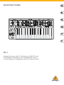 1
1
-
 2
2
-
 3
3
-
 4
4
-
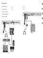 5
5
-
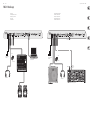 6
6
-
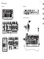 7
7
-
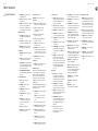 8
8
-
 9
9
-
 10
10
-
 11
11
-
 12
12
-
 13
13
-
 14
14
-
 15
15
-
 16
16
-
 17
17
-
 18
18
-
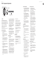 19
19
-
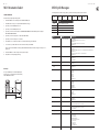 20
20
-
 21
21
-
 22
22
-
 23
23
-
 24
24


Behringer MS-1-RD Guida Rapida
- Categoria
- Sintetizzatore
- Tipo
- Guida Rapida
- Questo manuale è adatto anche per
in altre lingue
- English: Behringer MS-1-RD Quick start guide
- français: Behringer MS-1-RD Guide de démarrage rapide
- español: Behringer MS-1-RD Guía de inicio rápido
- Deutsch: Behringer MS-1-RD Schnellstartanleitung
- português: Behringer MS-1-RD Guia rápido
Documenti correlati
-
Behringer POLY D Guida Rapida
-
Behringer SX2442FX Guida Rapida
-
Behringer BH 770 Guida utente
-
Behringer Crave Guida Rapida
-
Behringer HC 2000 Guida Rapida
-
Behringer BH 470 Guida utente
-
Behringer HO 66 Guida Rapida
-
Behringer NEUTRON Guida Rapida
-
Behringer HLC 660M Guida Rapida
-
