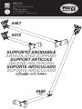
MO-EL BRACCIO SNODABILE 4467 - 4469 - 4472 Manuale del proprietario
- Tipo
- Manuale del proprietario

MO-EL S.p.a.
Via Galvani, 18
42027 Montecchio Emilia (RE)
ITALY
tel +39 (0522) 868011
fax +39 (0522) 864223
www.mo-el.com - [email protected]
SUPPORTO SNODABILE
ARTICULATED SUPPORT
SUPPORT ARTICULÉ
GELENK-HALTERUNG
SOPORTE ARTICULADO
SUPORTE ARTICULADO
4467
4469
+4467
4472

2
IT USO E MANUTENZIONE
1. AVVERTENZE IMPORTANTI PER LA SICUREZZA
Prima di utilizzare il supporto snodabile 4467, leggete attentamente le istruzi-
oni contenute in questo manuale, poiché contiene importanti informazioni
riguardo alla sicurezza dell’installazione, l’uso e la manutenzione.
Il manuale deve essere conservato e trasmesso al nuovo utente in caso di
cessione dell’apparecchio.
1. Il supporto snodabile 4467 è destinato esclusivamente all’impie-
go per il quale è stato progettato, ovvero il ssaggio del riscalda-
tore; il Costruttore non può essere considerato responsabile per
danni eventualmente provocati da un uso inadeguato.
2. Dopo aver disimballato il prodotto, vericarne la completezza e
assicurarsi che non presenti segni di rotture, danneggiamenti o
manomissioni.
3. Tenere il materiale d’imballaggio lontano dai bambini, perché può
essere fonte di pericolo.
4. L’apparecchio può essere utilizzato da bambini di almeno 8 anni
(come pure da persone con ridotte capacità siche, sensoriali
o mentali, o prive di esperienza o della necessaria conoscenza)
purché essi siano sotto sorveglianza, oppure dopo che abbiano
ricevuto istruzioni relative all’uso sicuro e abbiano compreso i po-
tenziali pericoli. I bambini non devono giocare con l’apparecchio.
La pulizia e la manutenzione devono essere fatte dall’utilizzatore
e non da bambini privi di sorveglianza.
5. Non apportare modiche al prodotto che compromettano la si-
curezza.
6. Questo prodotto è un accessorio che non è messo a terra, quindi
il cavo d’alimentazione che passerà al suo interno deve essere in
doppio isolamento.
7. Si sconsiglia di posizionare il prodotto in zone ad alto rischio sis-
mico o soggette a forti venti.
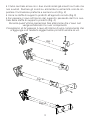
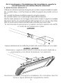
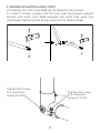
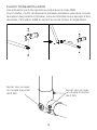
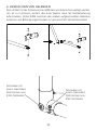
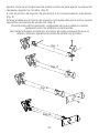
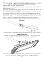
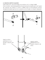
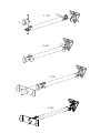
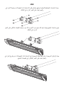
2. ASSEMBLAGGIO E POSIZIONAMENTO
• Unire saldamente tutti i pezzi della confezione con vite e dado
come mostrato in gura. Una volta adeguatamente avvicinati i pezzi
tra di loro, posizionarli all’inclinazione desiderata e stringere bene
vite e dado. Il dado deve essere posizionato nell’apposito invito esa-
gonale, la vite andrà dal lato opposto.(Fig. 1)

3
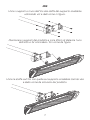
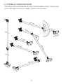
• Il tubo centrale arriva con i due snodi iniziali già inseriti sul tubo ma
non avvitati. Ruotare gli snodi su entrambe le estremità così da im-
postare l’inclinazione preferita e serrare le viti.(Fig. 2)
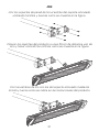
• Unire la staffa di supporto prodotti all’apposito snodo.(Fig.3)
• Far passare il cavo all’interno del supporto passando dal foro cen-
trale della staffa di supporto prodotti.(Fig. 4)
Durante quest’ultima operazione fare attenzione che il cavo non
venga schiacciato tra i vari componenti.
Consigliamo di far passare il cavo all’interno di ogni componente che
si aggiunge e di tenderlo leggermente prima di serrare le viti.
Fig. 1
Fig. 2
Fig. 3
Fig. 4

4
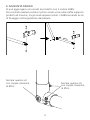
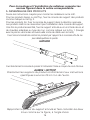
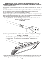
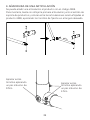
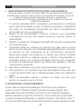
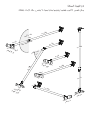
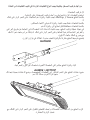
3. AGGIUNTA SNODO
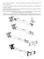
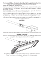
Si può aggiungere uno snodo al prodotto con il codice 4469.
Per montarlo basterà svitare il primo snodo vicino alla staffa supporto
prodotti ed inserire, tra gli snodi appena svitati, il 4469 serrando le viti
di ssaggio nell’angolazione desiderata.
4469
Serrare queste viti
con coppia massima
di 9Nm
Serrare queste viti
con coppia massima
di 4Nm

5
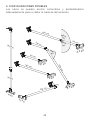
4. CONFIGURAZIONI POSSIBILI
I tubi si possono accorciare tagliandoli e sbavandoli accuratamente in
modo da non danneggiare il cavo di alimentazione.
100 cm
50 cm
100 cm
50 cm
10 cm
50 cm
100 cm
100 cm100 cm
100 cm100 cm
50 cm50 cm
MAX
45°
MAX
90°
MAX
90°
MAXMAX
6Kg6Kg
MAXMAX
10Kg10Kg
MAXMAX
3,2Kg3,2Kg
MAXMAX
3,2Kg3,2Kg
MAXMAX
10Kg10Kg
MAXMAX
3,2Kg3,2Kg

6
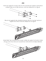
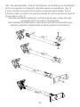
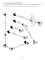
Per il montaggio e l’installazione del riscaldatore, seguite le
norme riportate nel relativo libretto istruzioni.
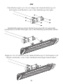
5. MONTAGGIO PRODOTTI
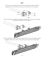
Utilizzare le indicazioni riportare di seguito per montare i singoli riscaldatori sul palo.
Per i prodotti Aaren o HotTop fissare la staffa di supporto dei prodotti come in
Fig.3.
Per i prodotti Iris fissare la staffa di supporto nel verso opposto.
Per i prodotti Hathor non ci sarà bisogno della staffa di supporto.
Alla fine delle operazioni di montaggio del prodotto, fissare il supporto snodabile
alla parete tramite viti e tasselli adeguati alla tipologia di muro come in Fig.1(trian-
golo con punta verso il basso ed eventuale uscita del cavo verso l’alto).
Si raccomanda di posizionare il prodotto centrato rispetto alla staffa
in modo da non sbilanciare il peso.
Posizionare i supporti del prodotto come da istruzioni dedicate e Posizionare i supporti del prodotto come da istruzioni dedicate e
posizionarle a circa 25cm di distanza l’uno dell’altro.posizionarle a circa 25cm di distanza l’uno dell’altro.
Avvicinare il prodotto al supporto snodabile e far coincidere i due fori Avvicinare il prodotto al supporto snodabile e far coincidere i due fori
come in figura definendo l’angolazione scelta.come in figura definendo l’angolazione scelta.
AAREN / HOTTOP
HATHOR
Fissare direttamente la staffa del prodotto allo snodo finale con viti e dadi.Fissare direttamente la staffa del prodotto allo snodo finale con viti e dadi.

7
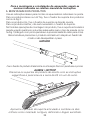
IRIS
Unire i supporti a muro dell’Iris alla staffa del supporto snodabile Unire i supporti a muro dell’Iris alla staffa del supporto snodabile
utilizzando viti e dadi come in figura.utilizzando viti e dadi come in figura.
Posizionare i supporti del prodotto a circa 25cm di distanza l’uno Posizionare i supporti del prodotto a circa 25cm di distanza l’uno
dell’altro e far coincidere i fori come da figura.dell’altro e far coincidere i fori come da figura.
Unire le staffe sull’Iris con quelle sul supporto snodabile tramite vite Unire le staffe sull’Iris con quelle sul supporto snodabile tramite vite
e dado come da istruzioni del prodotto.e dado come da istruzioni del prodotto.

8
EN USE AND MAINTENANCE
1. IMPORTANT SAFETY WARNINGS
Before using the articulated support 4467, read the instructions given in
this manual carefully, as they contain important safety information for
installation, use and maintenance.
The manual must be stored carefully and handed over to the new user in
the event of the equipment being transferred to others.
1. The articulated support 4467 must be used exclusively for the
purpose for which it was designed, i.e. for xing the heater;
the Manufacturer shall not be liable for any damage caused by
improper use.
2. Having removed the product from the packaging, check that it is
complete and make sure there are no signs of breakages, damage
or tampering.
3. Keep the package out of the reach of children, as it could constitute
a source of danger.
4. The equipment may be used by children over the age of eight
(or persons with reduced physical, sensory or mental capacities,
or without the required knowledge or experience) only under
supervision or once they have received appropriate training in the
safe use and potential hazards of the equipment. Children may not
play with the equipment. Cleaning and maintenance must only be
performed by the user and not by unsupervised children.
5. Do not modify the product in any way as this could compromise
its safety.
6. This product is an accessory and it is not earthed. For this reason,
the supply cable passing through it must be double insulated.
7. We do not recommend installing the product in areas where the
risk of earthquake or strong winds is high.
2. ASSEMBLY AND POSITIONING
• Join all the pieces in the package securely with screw and nut as
shown in the gure. Bring the pieces suitably close to each other;
then position them in the desired inclination and securely tighten
the screw and nut. Place the nut in the specic hexagon recess; the
screw goes on the opposite side (Fig. 1).
• The rst two articulated joints arrive already mounted on the central
tube but they are not screwed in place. Rotate the articulated joints

9
from the two ends to set the preferred inclination and tighten the
screws (Fig. 2).
• Join the product support bracket and the specic articulated joint
together (Fig.3).
• Pass the cable through the central hole of the product support bracket
and inside the support (Fig. 4).
During this last operation, make sure the cable does not get pinched
in between the various components.
We recommend passing the cable through components one by one,
as they are added, and to pull it slightly before tightening the screws.
Fig. 1
Fig. 2
Fig. 3
Fig. 4

10
3. ADDING AN ARTICULATED JOINT
Articulated joint with code 4469 can be added to the product.
To install it, simply unscrew the rst joint near the product support
bracket and insert joint 4469 between the joints that were just
unscrewed, tightening the xing screws at the desired angle.
4469
Tighten this screw
to a maximum
torque of 9 Nm
Tighten this screw
to a maximum
torque of 4 Nm

11
4. POSSIBLE CONFIGURATIONS
The tubes can be shortened. Simply cut and deburr them, taking care
not to damage the power supply cable in the process.
100 cm
50 cm
100 cm
50 cm
10 cm
50 cm
100 cm
100 cm100 cm
100 cm100 cm
50 cm50 cm
MAX
45°
MAX
90°
MAX
90°
MAXMAX
6 Kg6 Kg
MAXMAX
10 Kg10 Kg
MAXMAX
3.2 Kg3.2 Kg
MAXMAX
3.2 Kg3.2 Kg
MAXMAX
10 Kg10 Kg
MAXMAX
3.2 Kg3.2 Kg

12
Comply with the standards described in the relative instruction
book for assembly and installation of the heater.
5. INSTALLING THE PRODUCTS
Use the instructions below to install the single heaters onto the pole.
For Aaren and HotTop models, secure the product support bracket
as shown in Fig.3.
For Iris models, secure the support bracket in the opposite direction.
Hathor models do not require a support bracket.
After installing the product, fasten the articulated support to the wall
using screws and anchors suited to the type of wall and as shown in
Fig.1 (triangle pointing downwards and cable exiting from the top).
We recommend positioning the product centrally on the bracket to
keep the weight balanced.
Position the supports for the product as per the specific instructions Position the supports for the product as per the specific instructions
and place them approximately 25 cm apart.and place them approximately 25 cm apart.
Bring the product near the articulated support and match the two Bring the product near the articulated support and match the two
holes as shown in the figure, defining the chosen angle.holes as shown in the figure, defining the chosen angle.
AAREN / HOTTOP
HATHOR
Secure the product bracket directly onto the final joint with screws and nuts.Secure the product bracket directly onto the final joint with screws and nuts.

13
IRIS
Join the Iris wall supports and the articulated support bracket Join the Iris wall supports and the articulated support bracket
together with the screws and nuts, as shown in the figure.together with the screws and nuts, as shown in the figure.
Place the product supports approximately 25 cm apart and match Place the product supports approximately 25 cm apart and match
the holes as shown in the figure.the holes as shown in the figure.
Join the brackets on the Iris product and those on the articulated support Join the brackets on the Iris product and those on the articulated support
together with screw and nut, according to the product instructions.together with screw and nut, according to the product instructions.

14
FR UTILISATION ET ENTRETIEN
1. RECOMMANDATIONS IMPORTANTES DE SÉCURITÉ
Avant d’utiliser le support articulé 4467, lire attentivement les instructions
figurant dans la présente notice, laquelle contient des informations importantes
relatives à la sécurité de l’installation, à l’utilisation et à l’entretien.
La notice doit être conservée et remise à tout nouvel utilisateur en cas de
cession de l’appareil.
1. Le support articulé 4467 est exclusivement destiné à l’utilisation
pour laquelle il a été conçu, à savoir la xation du radiateur ; le
Fabricant décline toute responsabilité en cas de dommages
provoqués par une utilisation non conforme.
2. Après avoir déballé le produit, s’assurer qu’il est complet et qu’il
ne présente aucun signe de rupture, de dommage ou d’altération.
3. Conserver le matériau d’emballage hors de la portée des enfants
car il constitue une source de danger.
4. L’appareil peut être utilisé par des enfants d’au moins 8 ans, ainsi
que par des personnes dont les capacités physiques, sensorielles
ou mentales seraient réduites, voire qui ne posséderaient pas
l’expérience ni les connaissances nécessaires, à condition qu’ils
soient surveillés ou qu’ils aient reçu les instructions d’utilisation
nécessaires et qu’ils soient conscients des risques potentiels.
Les enfants ne doivent pas jouer avec l’appareil. Le nettoyage
et l’entretien doivent être effectués par l’utilisateur et ne doivent
pas être conés à des enfants sans surveillance.
5. Ne pas apporter de modications à l’appareil qui en
compromettraient la sécurité.
6. Ce produit est un accessoire qui n’est pas relié à la terre, le cordon
d’alimentation qui passera à l’intérieur doit donc être doublement
isolé.
7. Éviter de placer le produit dans des zones à haut risque sismique
ou soumises à des vents violents.
2. ASSEMBLAGE ET POSITIONNEMENT
• Assembler fermement toutes les pièces de l’emballage à l’aide
d’une vis et d’un écrou, comme indiqué sur la gure. Une fois les
pièces correctement assemblées, les positionner selon l’inclinaison
souhaitée et bien serrer la vis et l’écrou. L’écrou doit être placé
dans la cavité hexagonale, et la vis sur le côté opposé (Fig. 1).

15
• Le tube central est fourni avec les deux premières articulations déjà
insérées, mais non vissées, sur le tube. Tourner les articulations aux
deux extrémités pour régler l’inclinaison et serrer les vis (Fig. 2).
• Fixer la console de support des produits à l’articulation (Fig. 3).
• Faire passer le câble à l’intérieur du support à travers le trou central
de la console de support des produits (Fig. 4).
Durant cette dernière opération, veiller à ce que le câble ne soit pas
écrasé entre les différents composants.
Nous conseillons de faire passer le câble à l’intérieur de chaque
composant ajouté et de le tendre légèrement avant de serrer les vis.
Fig. 1
Fig. 2
Fig. 3
Fig. 4

16
3. AJOUT D’UNE ARTICULATION
Une articulation peut être ajoutée au produit avec le code 4469.
Pour l’installer, il suft de dévisser la première articulation près de la console
de support des produits et d’insérer, entre les articulations qui viennent d’être
dévissées, l’articulation 4469 en serrant les vis de xation à l’angle désiré.
4469
Serrer ces vis avec
un couple maximal
de 9 Nm
Serrer ces vis avec
un couple maximal
de 4 Nm

17
4. CONFIGURATIONS POSSIBLES
Les tubes peuvent être raccourcis en les coupant et en les ébavurant
soigneusement pour ne pas endommager le câble électrique.
100 cm
50 cm
100 cm
50 cm
10 cm
50 cm
100 cm
100 cm100 cm
100 cm100 cm
50 cm50 cm
MAX
45 °
MAX
90 °
MAX
90 °
MAXMAX
6 kg6 kg
MAXMAX
10 kg10 kg
MAXMAX
3,2 kg3,2 kg
MAXMAX
3,2 kg3,2 kg
MAXMAX
10 kg10 kg
MAXMAX
3,2 kg3,2 kg

18
Pour le montage et l’installation du radiateur, respecter les
normes figurant dans la notice correspondante.
5. ASSEMBLAGE DES PRODUITS
Suivre les instructions ci-après pour monter les radiateurs sur le mât.
Pour les produits Aaren ou HotTop, xer la console de support des produits
comme indiqué sur la Fig. 3.
Pour les produits Iris, xer la console de support dans la direction opposée.
Les produits Hathor ne nécessitent pas l’installation de la console de support.
Une fois le produit assemblé, xer le support articulé au mur à l’aide de vis et
de chevilles adaptées au type de mur, comme indiqué sur la Fig. 1 (triangle
avec la pointe vers le bas et éventuelle sortie de câble vers le haut).
Il est recommandé de centrer le produit par rapport à la console afin de ne
pas déséquilibrer le poids.
Positionner les supports du produit conformément aux instructions Positionner les supports du produit conformément aux instructions
spécifiques à environ 25 cm l’un de l’autre.spécifiques à environ 25 cm l’un de l’autre.
Rapprocher le produit du support articulé et faire coïncider les deux Rapprocher le produit du support articulé et faire coïncider les deux
trous comme sur la figure, à l’angle choisi.trous comme sur la figure, à l’angle choisi.
AAREN / HOTTOP
HATHOR
Fixer directement la console du produit à l’articulation finale au moyen de vis et d’écrous.Fixer directement la console du produit à l’articulation finale au moyen de vis et d’écrous.

19
IRIS
Fixer les supports muraux de Iris à la console du support articulé en Fixer les supports muraux de Iris à la console du support articulé en
utilisant des vis et des écrous, comme indiqué sur la figure.utilisant des vis et des écrous, comme indiqué sur la figure.
Placer les supports du produit à environ 25 cm l’un de l’autre et Placer les supports du produit à environ 25 cm l’un de l’autre et
aligner les trous comme indiqué sur la figure.aligner les trous comme indiqué sur la figure.
Assembler les consoles de Iris avec celles du support articulé à l’aide Assembler les consoles de Iris avec celles du support articulé à l’aide
d’une vis et d’un écrou en suivant les instructions correspondantes.d’une vis et d’un écrou en suivant les instructions correspondantes.

20
DE BEDIENUNG UND WARTUNG
1. WICHTIGE SICHERHEITSHINWEISE
Vor dem Gebrauch der Gelenkhalterung 4467 aufmerksam die Anweisungen in dieser
Bedienungsanleitung durchlesen, da diese wichtige Informationen zur Sicherheit bei
Installation, Gebrauch und Wartung enthält.
Die Bedienungsanleitung muss aufbewahrt und im Fall einer Weitergabe des Geräts
dem neuen Benutzer übergeben werden.
1. Die Gelenkhalterung 4467 ist ausschließlich für den Gebrauch bestimmt,
für den sie entwickelt wurde, d. h. zur Befestigung des Heizstrahlers.
Der Hersteller haftet nicht für Schäden, die auf einen unsachgemäßen
Gebrauch zurückzuführen sind.
2. Das Gerät nach dem Auspacken auf Vollständigkeit prüfen und sicherstellen,
dass keine Anzeichen von Rissen oder Brüchen, Beschädigungen oder
Manipulationen vorhanden sind.
3. Das Verpackungsmaterial von Kindern fernhalten, da es eine Gefahr
darstellen kann.
4. Das Gerät kann von Kindern mit einem Alter von mindestens 8 Jahren
(wie auch von Menschen mit eingeschränkten körperlichen und geistigen
Fähigkeiten oder eingeschränkter Sinneswahrnehmung oder ohne
Erfahrung oder notwendige Kenntnisse) verwendet werden, sofern diese
unter Aufsicht sind oder nachdem sie Anweisungen zum sicheren Gebrauch
erhalten und die potenziellen Gefahren verstanden haben. Kinder dürfen
nicht mit dem Gerät spielen. Reinigung und Wartung müssen durch den
Benutzer durchgeführt werden und nicht durch unbeaufsichtigte Kinder.
5. Keine Änderungen am Produkt vornehmen, welche die Sicherheit
beeinträchtigen können.
6. Dieses Zubehörteil ist nicht geerdet, das Stromkabel, das durch sein
Inneres geführt wird, muss also eine doppelte Isolierung aufweisen.
7. Es wird nicht empfohlen, das Produkt in stark erdbebengefährdeten
Gegenden oder in Zonen mit starken Winden aufzustellen.
2. MONTAGE UND AUFSTELLUNG
• Alle Teile in der Verpackung mit Schrauben und Muttern fest miteinander
verschrauben, wie in der Abbildung gezeigt. Nachdem die Teile im richtigen
Verhältnis zueinander gesetzt wurden, gewünschte Neigung einstellen
und Schrauben und Muttern gut festziehen. Die Mutter ist in dem
entsprechenden sechseckigen Einsatz zu positionieren, die Schraube an der
gegenüberliegenden Seite (Abb. 1).
La pagina si sta caricando...
La pagina si sta caricando...
La pagina si sta caricando...
La pagina si sta caricando...
La pagina si sta caricando...
La pagina si sta caricando...
La pagina si sta caricando...
La pagina si sta caricando...
La pagina si sta caricando...
La pagina si sta caricando...
La pagina si sta caricando...
La pagina si sta caricando...
La pagina si sta caricando...
La pagina si sta caricando...
La pagina si sta caricando...
La pagina si sta caricando...
La pagina si sta caricando...
La pagina si sta caricando...
La pagina si sta caricando...
La pagina si sta caricando...
La pagina si sta caricando...
La pagina si sta caricando...
La pagina si sta caricando...
La pagina si sta caricando...
-
 1
1
-
 2
2
-
 3
3
-
 4
4
-
 5
5
-
 6
6
-
 7
7
-
 8
8
-
 9
9
-
 10
10
-
 11
11
-
 12
12
-
 13
13
-
 14
14
-
 15
15
-
 16
16
-
 17
17
-
 18
18
-
 19
19
-
 20
20
-
 21
21
-
 22
22
-
 23
23
-
 24
24
-
 25
25
-
 26
26
-
 27
27
-
 28
28
-
 29
29
-
 30
30
-
 31
31
-
 32
32
-
 33
33
-
 34
34
-
 35
35
-
 36
36
-
 37
37
-
 38
38
-
 39
39
-
 40
40
-
 41
41
-
 42
42
-
 43
43
-
 44
44


MO-EL BRACCIO SNODABILE 4467 - 4469 - 4472 Manuale del proprietario
- Tipo
- Manuale del proprietario
in altre lingue
- français: MO-EL BRACCIO SNODABILE 4467 - 4469 - 4472 Le manuel du propriétaire
- español: MO-EL BRACCIO SNODABILE 4467 - 4469 - 4472 El manual del propietario
- Deutsch: MO-EL BRACCIO SNODABILE 4467 - 4469 - 4472 Bedienungsanleitung
- português: MO-EL BRACCIO SNODABILE 4467 - 4469 - 4472 Manual do proprietário
Altri documenti
-
V2 Elettronica V2 Blitz Manuale del proprietario
-
CAME FAST Guida d'installazione
-
Telcoma TEN2 Manuale del proprietario
-
Sunrise Medical Quickie IRIS Manuale del proprietario
-
 Key Automation 580ISMEWA Manuale utente
-
-
-
HiTEC Kit DogFighter Manuale del proprietario
-
-
IRIS ZIPPIE Manuale del proprietario
