Viessmann 5067 Manuale del proprietario
- Categoria
- Accessori per la preparazione del caffè
- Tipo
- Manuale del proprietario

Bedienungsanleitung
Operation Manual
Innovation,
die bewegt!
5066
Zündmodul für Gaslaternen
Ignition module for gas lamps
5067
Leuchtstoffröhren-Simulator
Fluorescent lamp-simulator
5066
5067
Auch zum Betrieb
mit LED-Leuchten!
For connection with
LED lights!
AC
~
DC
=
1. Wichtige Hinweise / Important information ........................................................ 2
2. Einleitung / Introduction ..................................................................................... 2
3. Anschluss / Connection ..................................................................................... 4
4. Technische Daten / Technical data .................................................................... 4

2
DE EN
1. Wichtige Hinweise
Bitte lesen Sie vor der ersten Anwendung des Produktes
bzw. dessen Einbau diese Bedienungsanleitung auf-
merksam durch. Bewahren Sie diese auf, sie ist Teil des
Produktes.
1.1 Sicherheitshinweise
Vorsicht:
Verletzungsgefahr!
Für die Montage sind Werkzeuge nötig.
Stromschlaggefahr!
Die Anschlussdrähte niemals in eine Steckdose einfüh-
ren! Verwendetes Versorgungsgerät (Transformator,
Netzteil) regelmäßig auf Schäden überprüfen. Bei Schä-
den am Versorgungsgerät dieses keinesfalls benutzen!
Alle Anschluss- und Montagearbeiten nur bei abgeschal
-
teter Betriebsspannung durchführen!
Ausschließlich nach VDE/EN gefertigte Modellbahn-
transformatoren verwenden!
Stromquellen unbedingt so absichern, dass es bei einem
Kurzschluss nicht zum Kabelbrand kommen kann.
1.2 Das Produkt richtig verwenden
Dieses Produkt ist bestimmt:
- Zum Einbau in Modelleisenbahnanlagen und Dioramen.
- Zum Anschluss an einen Modellbahntransformator
(z. B. Art. 5200) bzw. an eine Modellbahnsteuerung mit
zugelassener Betriebsspannung.
- Zum Betrieb in trockenen Räumen.
Jeder darüber hinausgehende Gebrauch gilt als nicht be-
stimmungsgemäß. Für daraus resultierende Schäden haftet
der Hersteller nicht.
1.3 Packungsinhalt überprüfen
Kontrollieren Sie den Lieferumfang auf Vollständigkeit:
- Modul
- 2 Schrauben
- 6 gelbe Stecker
- Grüner Stecker
- Brauner Stecker
- Anleitung
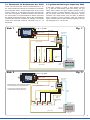
2. Einleitung
Die Module steuern Modellbahn-Leuchten bzw. Gaslater-
nen, die an die 5 Modulausgänge angeschlossen werden
(Abb. 1).
1. Important information
Please read this manual completely and attentively before
using the product for the first time. Keep this manual. It is
part of the product.
1.1 Safety instructions
Caution:
Risk of injury!
Tools are required for installation.
Electrical hazard!
Never put the connecting wires into a power socket!
Regularly examine the transformer for damage. In case
of any damage, do not use the transformer.
Make sure that the power supply is switched off when
you mount the device and connect the cables!
Only use VDE/EN tested special model train transform-
ers for the power supply!
The power sources must be protected to avoid the risk
of burning cables.
1.2 Using the product for its correct purpose
This product is intended:
- For installation in model train layouts and dioramas.
- For connection to an authorized model train transformer
(e. g. item 5200) or a digital command station.
- For operation in dry rooms only.
Using the product for any other purpose is not approved
and is considered inappropriate. The manufacturer is not
responsible for any damage resulting from the improper
use of this product.
1.3 Checking the package contents
Check the contents of the package for completeness:
- Module
- 2 screws
- 6 yellow plugs
- Green plug
- Brown plug
- Manual
2. Introduction
The modules control model train lights resp. gas lamps,
connected to the 5 module plugs (fig. 1).

3
Sekundär
0-10-16 V~
16 V
Primär
230 V~
Gefertigt nach
VDE 0570
EN 61558
Lichttransformator
5200
Nur für trockene Räume
Primär 230 V 50 - 60 Hz
Sekundär max. 3,25 A52 VA
ta 25°CIP 40
10 V
0 V
grüner Stecker
green plug
gelber Stecker
yellow plug
grüner Stecker
green plug
z. B. / e. g.
5547
z. B. / e. g.
6011
braun / brown
gelb / yellow
5x
gelb
yellow
braun / brown
gelb / yellow
blau
blue
5066
z. B. / e. g. 5200
viessmann
Zündmodul für
Gaslaternen 5066
16 V ~A n/Aus
bn
L1 L2 L3 L4 L5
ge
viessmann 5547
Universal Tasten - Stellpult
Abb. 1 Fig. 1
In case of DC voltage, the brown
cable indicates the positive pole
Bei Gleichstrom wird das braune Kabel
an dem positiven Pol angeschlossen
Abb. 2 Fig. 2
grüner Stecker
green plug
gelber Stecker
yellow plug
grüner Stecker
green plug
z. B. / e. g.
5550/5547
z. B. / e. g.
6365
z. B. / e. g.
6950
Sekundär
0-10-16 V~
16 V
Primär
230 V~
Gefertigt nach
VDE 0570
EN 61558
Lichttransformator
5200
Nur für trockene Räume
Primär 230 V 50 - 60 Hz
Sekundär max. 3,25 A52 VA
ta 25°CIP 40
10 V
0 V
braun / brown
gelb / yellow
5x
gelb
yellow
braun / brown
gelb / yellow
blau
blue
5067
z. B. / e. g. 5200
viessmann
Leuchtstoffröhren-
Simulator 5067
16 V ~A n/Aus
bn
L1 L2 L3 L4 L5
ge
viessmann 5550
2.1 Zündmodul für Gaslaternen Art. 5066
Nach dem Einschalten mittels Tastenstellpult (z. B.
Art. 5547) fangen die Laternen an zu flackern und werden
dann langsam heller. Jedes Zündmuster ist ein wenig
anders. Nach ca. 5 Sekunden erreichen die Laternen
ihre volle Leuchtkraft. Im Betrieb flackern die Laternen
hin und wieder zu unterschiedlichen Zeiten (simuliert
die Gasdruckschwankungen). Nach dem Ausschalten
leuchten alle Laternen zunächst mit mäßiger Leuchtkraft
weiter und erlöschen vollends innerhalb von ca. 1,5
Sekunden.
2.1 Ignition module for gas lamps item 5066
If the input “An/Aus” is given a short electric contact
(e. g. with the push-button panel item 5547), the gas
lamps start to flicker and grow brighter gradually. Every
ignition process is slightly different. After ca. 5 seconds
the gas lamps reach their maximum brightness. During
operation, the lamps flicker now and then at different
times (variations of gas pressure). After the switch-off
signal, all lamps shine on with moderate brightness and go
off completely in ca. 1.5 seconds.

Modellbauartikel, kein Spielzeug! Nicht geeignet für
Kinder unter 14 Jahren! Anleitung aufbewahren!
Model building item, not a toy! Not suitable for children
under the age of 14 years! Keep these instructions!
Ce n’est pas un jouet! Ne convient pas aux enfants de moi-
ns de 14 ans! Conservez cette notice d’instructions!
Não é um brinquedo! Não aconselhável para menores de
14 anos! Conservar o manual de instruções!
Modelbouwartikel, geen speelgoed! Niet geschikt voor
kinderen onder 14 jaar! Gebruiksaanwijzing bewaren!
Articolo di modellismo, non è un giocattolo! Non adatto
a bambini al di sotto dei 14 anni! Conservare istruzioni per
l’uso!
Artículo para modelismo ¡No es un juguete! No
recomendado para menores de 14 años! Conserva las
instrucciones de servicio!
DE
EN
FR
NL
IT
ES
PT
Made in Europe
Viessmann
Modelltec
hnik GmbH
Bahnhofstraße 2a
D - 35116 Hatzfeld-Reddighausen
+49 6452 9340-0
www.viessmann-modell.de
4
92135
Stand 07/sw
03/2022
Ho/Kf
2.2 Leuchtstoffröhren-Simulator
Art. 5067
Nach dem Einschalten der Leuchten mittels Tastenstellpult
(z. B. Art. 5547) flackern die einzelnen Röhren vorbildge-
recht eine Zeit lang, bis sie nach und nach alle leuchten.
Dabei ist jedes Zündmuster ein wenig anders.
Wenn Sie den Steuerausgang („An/Aus“) über einen Ein-
Aus-Schalter (z. B. Art. 5550) dauerhaft mit Masse verbin-
den, wird an Ausgang L5 eine defekte Leuchtstoffröhre
simuliert (siehe Abb. 2). Diese flackert in unregelmäßigen
Abständen kurz auf, wobei diese mal schnell und mal
langsam hell wird.
3. Anschluss
Die Bausteine sind für den Anschluss an 10 – 16 V Gleich-
oder Wechselspannung vorgesehen. Der maxi-male Aus-
gangsstrom von 100 mA pro Ausgang reicht in der Regel
zum Anschluss von 2 bis 3 Glühlampen oder LEDs, denn
die Stromaufnahme einer Viessmann-Leuchte beträgt ma-
ximal 30 mA pro Glühlampe/LED. Wir empfehlen jedoch,
je Ausgang nur eine Leuchte zu betreiben, da sich auch in
der Realität nie 2 Leuchten gleich verhalten.
Der prinzipielle Anschluss ist in Abb. 1 dargestellt und gilt
für beide Artikel.
4. Technische Daten
Betriebsspannung: 10 – 16 Volt AC~/DC=
Stromaufnahme (ohne Lampen): ca. 20 mA
Ausgänge 1 – 5:
Max. Strom pro Ausgang: 100 mA
2.2 Fluorescent lamp-simulator
item 5067
If the input “An/Aus” is given a short electric contact
(e. g. with the push-button panel item 5547), the
different fluorescent tubes flicker for a moment before all
of them light one after the other. The turning on pattern is
a little different for each of the tubes.
By using an universal on-off switch (e. g. item 5550) the
input (“An/Aus”) is switched to earth permanently and a
defective tube is simulated on output L5 (fig. 2). This tube
flickers at irregular intervals, at times brightening quickly,
at times slowly.
3. Connection
The modules are designed for connection to 10 – 16 Volt
direct (DC) or alternating (AC) voltage. The maximum
current of 100 mA per output is normally sufficient for the
connection of 2 or 3 bulbs or LEDs. The current consump-
tion of a Viessmann lamp is up to 30 mA for each bulb/
LED. We recommend connection of only one lamp to each
output, since no two lamps will ever behave exactly the
same way in reality.
The connection in principle for both modules is shown in
fig. 1.
4. Technical data
Operating voltage: 10 – 16 V AC~/DC=
Current consumption (without bulbs): ca. 20 mA
Outputs 1 – 5:
Max. current loading: 100 mA
Änderungen vorbehalten. Keine Haftung für Druckfehler
und Irrtümer.
Die aktuelle Version der Anleitung finden Sie auf der Viess-
mann Homepage unter der Artikelnummer.
Subject to change without prior notice. No liability for
mistakes and printing errors.
You will find the latest version of the manual on the Viess-
mann website using the item number.
Entsorgen Sie dieses Produkt nicht über den
(unsortierten) Hausmüll, sondern führen Sie
es der Wiederverwertung zu.
Do not dispose of this product through (unsorted)
domestic waste, supply it to recycling instead.
-
 1
1
-
 2
2
-
 3
3
-
 4
4


Viessmann 5067 Manuale del proprietario
- Categoria
- Accessori per la preparazione del caffè
- Tipo
- Manuale del proprietario
in altre lingue
- English: Viessmann 5067 Owner's manual
- Deutsch: Viessmann 5067 Bedienungsanleitung