Elkron MS04PK Guida d'installazione
- Categoria
- Illuminazione di comodità
- Tipo
- Guida d'installazione
Questo manuale è adatto anche per

Microfono selettivoMicrofono selettivo
Microfono selettivoMicrofono selettivo
Microfono selettivo
VV
VV
Vault detectorault detector
ault detectorault detector
ault detector
IS1078-AC
DS80MS08-001 LBT80139
MS04MS04
MS04MS04
MS04
Microfono selettivo con copritoppaMicrofono selettivo con copritoppa
Microfono selettivo con copritoppaMicrofono selettivo con copritoppa
Microfono selettivo con copritoppa
VV
VV
Vault detector with keault detector with ke
ault detector with keault detector with ke
ault detector with keyhole pryhole pr
yhole pryhole pr
yhole protectionotection
otectionotection
otection
MS04PKMS04PK
MS04PKMS04PK
MS04PK
I/GB

IGB
(((ELKRON))) MS04/MS04PK
INDICE
1.0 DESCRIZIONE GENERALE.....................3
2.0 ELEMENTI PER IL FISSAGGIO...............4
3.0 ACCESSORI OPZIONALI ........................4
4.0 PRINCIPI DI INSTALLAZIONE .................5
5.0 DESCRIZIONE FONDO ...........................5
6.0 POSA IN OPERA......................................6
7.0 DESCRIZIONE SCHEDA .........................9
8.0 DESCRIZIONE MORSETTIERA ..............9
9.0 LED DI SEGNALAZIONE .........................10
10.0 PROGRAMMAZIONE TRAMITE
PONTICELLI.............................................10
11.0 MONTAGGIO SCHEDA ............................10
12.0 PRIMA ALIMENTAZIONE.........................10
13.0 REGOLAZIONI .........................................11
14.0 CARATTERISTICHE FUNZIONALI ..........14
15.0 INST. PERTURBATORE INTERNO ..........14
16.0 CARATTERISTICHE TECNICHE .............15
GUIDA ALLA SOLUZIONE DEI
PROBLEMI ...............................................16
17.0 COPRITOPPA - CAR. GENERALI............17
18.0 INSTALLAZIONE COPRITOPPA..............18
19.0 INGOMBRI DELL’OCCLUSORE ..............19
INDEX
1.0 GENERAL DESCRIPTION .......................3
2.0 FASTENING ELEMENTS .........................4
3.0 OPTIONAL ACCESSORIES.....................4
4.0 INSTALLATION PRINCIPLES...................5
5.0 FASTENING SURFACE DESCRIPTION ..5
6.0 FITTING....................................................6
7.0 BOARD DESCRIPTION............................9
8.0 TERMINALS DESCRIPTION ....................9
9.0 SIGNALLING LEDS ..................................10
10.0 JUMPER PROGRAMMING ......................10
11.0 BOARD MOUNTING.................................10
12.0 FIRST POWER ON ..................................10
13.0 SETTINGS................................................11
14.0 FUNCTIONAL CHARACTERISTICS ........14
15.0 INTERNAL PERTURBATOR
INSTALLATION.........................................14
16.0 TECHNICAL CHARACTERISTICS...........15
TROUBLESHOOTING..............................16
17.0 KEYHOLE PROTECTOR
GENERAL CHARACTERISTICS.............. 17
18.0
KEYHOLE PROTECTOR INSTALLATION ......
18
19.0
KEYHOLE PROTECTOR DIMENSIONS ......... 19
2

IGB
(((ELKRON))) MS04/MS04PK
1.0 DESCRIZIONE GENERALE
• Microfono selettivo per la segnalazione di allarme
contro tentativi di effrazione eseguiti a danno di strut-
ture murarie in cemento armato, casseforti, armadi
corazzati, casse continue, porteforti, etc..
•Tecnologia a microprocessore con gestione integral-
mente digitale del sensore
•Totale immunità dai disturbi esterni di natura elettro-
magnetica grazie al doppio isolamento galvanico tra
l’area delle connessioni e l’unità di rilevazione ed analisi
dei segnali.
•Autotest ciclico sui due canali di rilevazione, con co-
stante verifica d’integrità del trasduttore e della sezio-
ne d’amplificazione.
• Dotato di rivelatore termico a soglia, per rilevare ten-
tativi di attacco al microfono con dispositivi che alteri-
no in modo repentino la normale temperatura di fun-
zionamento
• Canali e modalità di rilevazione:
-Canale perforazione: 16 livelli di sensibilità, 4 - valo-
ri di integrazione (delay)
-Canale esplosione: 4 livelli di sensibilità
•Visualizzazione e memorizzazione delle differenti
tipologie di allarme
•
Test point per taratura e verifica strumentale sensibilità
• Comando “REMOTE” per l’attenuazione dei livelli di
sensibilità (applicazioni BANCOMAT)
•Doppio passaggio dei cavi :
- Verso la centrale, dotato di pressacavo
- Verso un eventuale sensore ausiliario, esterno al
microfono
• Grado di protezione IP54
• Predisposizione alloggiamento di un “perturbatore in-
terno” (opzionale), atto alla funzione di test operativo.
• Possibilità di gestione di “perturbatore esterno”
(opzionale), per test operativi su grandi superfici.
1.0 GENERAL DESCRIPTION
• Vault detector for signalling alarms for break-in attempts
on reinforced concrete walls, safes, armoured cabinets,
24-hour deposits, armoured doors, etc.
•Microprocessor technology with integral digital sensor
management.
•Total immunity from external electromagnetic interfer-
ence thanks to double galvanised isolation between
connections area and signal detection and analysis.
•Cyclic self-test on two detection channels, with con-
stant transducer and amplification section integrity test.
• Threshold heat detector for detecting attempt to at-
tack the microphone with external temperature device
which sharply influence the detector’s working
temperature.
• Detection channels and methods:
-Perforation channel: 16 levels of sensitivity, 4 - inte-
gration values (delay)
-Explosion channel: 4 levels of sensitivity
•View and storage of different types of alarm
•Test point for instrument testing
• “REMOTE” control for attenuating levels of sensitivity
(ATM applications)
•Double cable passage:
- To the control unit, with grommet
- To optional auxiliary sensor, external to microphone
•IP54 protection degree
• Set-up for “internal perturbator” housing (optional) , for
operative testing.
• Possibility of “external perturbator” management (op-
tional), for operative testing on large surfaces.
.
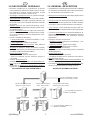
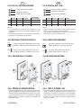
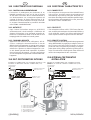
DIFFERENTI TIPOLOGIE DI MONTAGGIO
DIFFERENT ASSEMBLY METHODS
STRUTTURE METALLICHE
METALLIC STRUCTURES
STRUTTURE MURARIE
WALL STRUCTURES
STRUTTURE COMPOSITE
COMPOSITE STRUCTURES
CON KIT OPZIONALE (KT-TMP)
WITH KIT IN OPTION (KT-TMP)
ACCOPPIAMENTO DIRETTO
DIRECT JOINING
CON KIT OPZIONALE
SPA04
WITH KIT IN OPTION
SPA04
ACCOPPIAMENTO DIRETTO
DIRECT ASSEMBLY
ACCOPPIAMENTO INDIRETTO
INDIRECT ASSEMBLY
CON KIT OPZIONALE
SPA04
WITH KIT IN OPTION
SPA04
3

IGB
(((ELKRON))) MS04/MS04PK
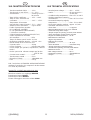
TASSELLI
BULLONI M6X60
BOLTS M6X60
EXPANSION BOLTS
BULLONI M6X20
BOLTS M6X20
ELEMENTI PER
FISSAGGIO
SU STRUTTURE
METALLICHE
ELEMENTI PER
FISSAGGIO
SU STRUTTURE
IN MURATURA
TAPPI GOMMA Ø 6
RUBBER CAPS
Ø
6
RONDELLA Ø 6X30
RONDELLA Ø 6X12
WASHER
Ø
6X12
ROSETTA Ø 6
ELEMENTI COMUNI PER TUTTI I TIPI DI FISSAGGIO
METALLIC
STRUCTURE
FASTENING
ELEMENTS
BRICK WALL
FASTENING
ELEMENTS
COMMON ELEMENTS FOR ALL FASTENING METHODS
WASHER
Ø
6X30
GROWER
Ø
6
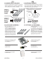
2.0 ELEMENTI PER IL FISSAGGIO
• Il microfono selettivo MS04 comprende una serie di
bulloni da utilizzare per il fissaggio su superfici me-
talliche (mezzi forti) e una serie di tasselli in metallo
e viti da utilizzare su superfici in muratura .
3.0 ACCESSORI OPZIONALI
• KIT di fissaggio su strutture
composite. (vedi par.6.3)
Qualora il microfono fosse da in-
stallare su strutture composite,
è possibile richiedere il KIT di fis-
saggio KT-TMP (KT4700111) co-
stituito da tasselli e viti adatte a
questo tipo di superficie. Per que-
sto tipo di tasselli è fornito inoltre
un particolare “punzone” utile per
l’applicazione dei suddetti tasselli.
• SPA04: KIT per montaggi indiretti
con piastra di accoppiamento
Cod. SP6900111
• Perturbatore interno MS04IT
Cod. MS1010111
(vedi Par. 15.0)
• Perturbatore esterno MS04ET
Cod. MS1110111
3.0 OPTIONAL ACCESSORIES
Composite structure fastening KIT
(see paragraph 6.3).
A fastening kit KT-TMP
(KT4700111) is available for fasten-
ing the microphone on composite
structures. The kit consists of ex-
pansion bolts and screws suitable
for this type of surface. Furthermore,
a special “punch” is provided for
applying the expansion bolts.
• SPA04: undirect assembly
KIT with coupling plate.
Cod. SP6900111
• Internal perturbator MS04IT
Code MS1010111
(see paragraph 15.0)
• External perturbator MS04ET
Code MS1110111
2.0 FASTENING ELEMENTS
• The MS04 selective microphone includes a set of bolts
to be used for fastening to metallic surfaces (heavy
duty material) and a set of metallic expansion bolts
and screws for fastening to brick walls
4

IGB
(((ELKRON))) MS04/MS04PK
4.0 PRINCIPI DI INSTALLAZIONE
• MS04 è stato concepito per le applicazioni tipiche di
alta sicurezza; è fondamentale quindi attenersi alle in-
dicazioni di installazione, che rivestono un carattere
essenziale per il buon funzionamento del microfono.
• Pertanto occorre considerare:
-le caratteristiche fisiche del mezzo da protegge-
re: in funzione del materiale con il quale è costituita
la struttura da proteggere, vi sono differenze di pro-
pagazione e assorbimento (in termini di frequenza),
tra metallo, calcestruzzo e cemento armato. Queste
differenze possono incidere sulla sensibilità dell’area
di copertura di un fattore DUE a UNO. Ad esempio a
parità di sistema di scasso, l’area di copertura del
rilevatore montato sul metallo, sarà circa doppia ri-
spetto al montaggio su una superficie di muratura.
-i possibili mezzi e modalità di effrazione: i mezzi
di effrazione, producono “segnali acustici” molto di-
versi tra loro. A parità di materiale con il quale è costi-
tuita la struttura da proteggere e alla stessa distanza
del rilevatore, un attacco attraverso una lancia termi-
ca genera segnali MILLE volte inferiori rispetto a quelli
prodotti da un trapano a percussione. Per contro a
parità di tempo, la lancia estrae dalla superficie un
volume di materiale CENTO volte superiore a quello
estratto con il trapano.
-il fissaggio del microfono: la capacità di rilevazione
dipende moltissimo anche da quanto il microfono sia
correttamente fissato alla struttura da proteggere. La
superficie di fissaggio dovrà essere bene in piano,
per favorire unitamente ad un’adeguata forza di
serraggio, una maggiore area di contatto tra il micro-
fono e la struttura.
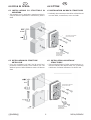
5.0 DESCRIZIONE FONDO
Afori di fissaggio del fondo
del microfono alla
struttura portante
Bfori per fissaggio coperchio
Cpredisposizione per
passaggio cavo ed
eventuale organo ausiliario
Dpassaggio cavo
(comprensivo di passacavo)
Eguarnizione di tenuta
Fpunti di fissaggio del
circuito stampato
Gcapsula piezoelettrica
Hfissaggio sistema
antiasportazione e/o
perturbatore interno
Ipredisposizione per pas-
saggio cavi
Lforo filettato per connessio-
ne a tubo flessibile
AA
F
F
F
F
G
BB
CD
E
I
H
L
4.0 INSTALLATION PRINCIPLES
• MS04 was designed for typical high security applica-
tions. For this reason, following the installation instruc-
tions is crucial. These are essential for the correct op-
eration of the microphone.
• The following aspects must be taken into account:
-The physical characteristics of the device to be
protected. There are differences in propagation and
absorption (in terms of frequency) between metal,
cement and reinforced concrete with which the struc-
ture to be protected is made. These differences can
effect the coverage area sensitivity TWO to ONE.
For example, given the same break-in system, the
coverage area of the detection system fitted on metal
will be approximately double with respect to fitting on
a brick surface.
-The possible break-in methods. The devices used
for breaking-in produce very different “acoustic sig-
nals”. Given the same material of the structure to be
protected and the same distance from the detector,
an attack made with a blow pipe will generate signals
ONE THOUSAND times lower than those of a per-
cussion drill. Conversely, in the same time, the blow
pipe can removed a volume of material ONE HUN-
DRED times larger than that extracted with the drill.
- Microphone fastening method. Detection capablility
greatly depends also on whether the microphone is
correctly fitted to the structurue to be protected. The
fastening structure must be level, to favour suitable
fastening tighteness and a greater area of contact
between the microphone and the structure.
5.0 FASTENING SURFACE
DESCRIPTION
5
Ahole for fastening bottom of
microphone
to load-bearing structure
Bholes for fastening cover
Cset-up for passing
wire and optional
auxiliary unit
Dwire passage
(including
grommet)
Eseals
Fprinted circuit
fastening points
Gpiezoelectric capsule
Hanti-tampering fastening
system and/or internal per-
turbator
Iset-up for wire passage
Lthreaded hole for correcting
to flexible tube

IGB
(((ELKRON))) MS04/MS04PK
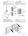
6.0 POSA IN OPERA
6.1 INSTALLAZIONI SU STRUTTURE IN
MURATURA
• Tali strutture sono in preferenza: pareti massiccie in
cemento armato i pavimenti in calcestruzzo, pietra o
simili
6.2 INSTALLAZIONI SU STRUTTURE
METALLICHE
• Sono da considerare tali tutti i tipi di mezzi forti,
porteforti, armadi corazzati, casse continue, etc.. che
abbiano spessori della blindatura esterna di almeno
5mm
6.0 FITTING
6.1 INSTALLATION ON BRICK STRUCTURES
• Preferably, these structures should be solid reinforced
concrete walls, cement floors, stone or similar.
6.2 INSTALLATION ON METALLIC
STRUCTURES
• These include all types of safes, armoured doors, ar-
moured cabinets, 24h deposit safes, etc., presenting
a thickness of external armature of at least 5 mm.
ANCORAGGIO SENSORE
DETECTOR FIXING
INSTALLAZIONE
ANTIASPORTAZIONE
ANTIREMOVAL
INSTALLATION
ANCORAGGIO SENSORE
DETECTOR FIXING
INSTALLAZIONE
ANTIASPORTAZIONE
ANTIREMOVAL
INSTALLATION
HSS
WIDIA
6

IGB
(((ELKRON))) MS04/MS04PK
6.3 INSTALLAZIONI SU STRUTTURE
COMPOSITE
• Appartengono a questa categoria molti mezzi forti co-
stituiti da agglomerati speciali ad altissimo carico di
rottura, miscelate con elementi abrasivi, ricoperti da
sottili lastre d’acciao inox o simili. Utilizzare per que-
ste strutture il kit KT-TMP.
FISSAGGIO TASSELLI
CON PERCUSSORE
6.4 INSTALLAZIONE INDIRETTA SU
STRUTTURE METALLICHE
• Nei casi in cui non sia possibile o risulti difficoltoso
operare delle filettature sulla struttura metallica, è pos-
sibile installare il microfono tramite la piastra (kit SPA04)
saldandola direttamente sul mezzo da proteggere.
ANCORAGGIO SENSORE
DETECTOR FIXING
INSTALLAZIONE
ANTIASPORTAZIONE
ANTIREMOVAL
INSTALLATION
EXPANSION BOLTS
FIXING WITH “PUNCH”
6.3 COMPOSITE STRUCTURE
INSTALLATIONS
• These include a wide variety of strong materials made
of special very high yield agglomerate filled with abra-
sive elements and covered with thin plates of stain-
less steel or similar. For this structures you can utilize
KT-TMP kit.
6.4 UNDIRECT FITTING ON STEEL
STRUCTURES
• In the cases in which it is not possible or difficult to
operate some edgings on the metallic structure, it is
possible to install the microphone through the plate
(kit SPA04) by directly welding it on the mean to protect.
ANCORAGGIO SENSORE
DETECTOR FIXING
INSTALLAZIONE
ANTIASPORTAZIONE
ANTIREMOVAL
INSTALLATION
HSS
WIDIA
HSS
WIDIA
7

IGB
(((ELKRON))) MS04/MS04PK
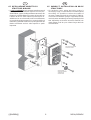
6.5 INSTALLAZIONE INDIRETTA SU
STRUTTURE MURARIE
• In casi eccezionali dove la struttura muraria presenti
delle asperità eccessivamente ampie che non sia pos-
sibile livellare, oppure risulti particolarmente tenace alla
foratura è possibile limitare il numero dei tasselli con
l’utilizzo del kit KT-TMP. Utilizzare questo tipo di in-
stallazione (con un solo tassello) solo se assolutamente
necessario tenendo presente che a seconda del tipo di
materiale si potrebbe verificare un prolungamento del
ritardo sull’allarme anche 4 volte superiore a quello
impostato.
ANCORAGGIO SENSORE
DETECTOR FIXING
INSTALLAZIONE
ANTIASPORTAZIONE
ANTIREMOVAL
INSTALLATION
• For particular cases, where the brick’s surface is
excessively rough, or it would be too resistant against
the drilling, it is possible to reduce the number of
necessary expansion bolts by using the KT-TMP kit.
Such kind of installation (using a single bolt) shall be
used only when mandatorily necessary, keeping in mind
that, depending on the brick structure’s material, the
alarm trigger could be up to 4 times longer than the
selected value.
6.5
UNDIRECT INSTALLATION ON BRICK
STRUCTURES
8

IGB
(((ELKRON))) MS04/MS04PK
8421
+
-
1234 1234
2121
+
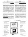
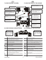
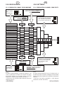
7.0 DESCRIZIONE SCHEDA
DIP-SWITCH REGOLAZIONE
INTEGRAZIONE CANALE PERFORAZIONE
DIP-SWITCH REGOLAZIONE
SENSIBILITA’ CANALE ESPLOSIONE
EXPLOSION CHANNEL INTENSITY
DIP SWITCH TRIMMER
LED P = CANALE PERFORAZIONE
LED T = CANALE TERMICO
LED E = CANALE ESPLOSIONE
LED P = PERFORATION CHANNEL
LED T = THERMAL CHANNEL
LED E = EXPLOSION CHANNEL
PONTICELLO PER ESCLUSIONE
ANTIASPORTAZIONE
ANTI-TAMPERING CUT-OUT JUMPER
PONTICELLO PER ESCLUSIONE
RILEVAZIONE TERMICA
HEAT DETECTION CUT-OUT JUMPER
7.0 DESCRIPTION OF THE BOARD
8.0 DESCRIZIONE MORSETTIERA
+ Positivo di alimentazione +12Vdc
EA Uscita elettrica di allarme OPEN
COLLECTOR (0 Vdc in allarme)
-R Ingresso di comando che portato a 0 Vdc
raddoppia l’integrazione programmata dal dip-
switch “RESPONSE”
- Negativo di alimentazione
Morsetto di appoggio per eventuale resistenza
di bilanciamento
Contatto NC relè di allarme
AUX Morsetti di appoggio per sensori ausiliari
(PERTURBATORI)
TAMPER
Contatti NC relè di sabotaggio (antiapertura/
antiasportazione/attacco termico)
Morsetto di appoggio per eventuale resistenza
di bilanciamento
ATTENZIONE
Isolare con una
guaina o nastro
isolante lo schermo
dal lato sensore
ALARM
DIP-SWITCH REGOLAZIONE
SENSIBILITA CANALE PERFORAZIONE
PERFORATION CHANNEL SENSITIVITY
DIP SWITCH TRIMMER
TEST POINT PER VERIFICA LIVELLO DI
RUMOROSITA’
NOISE LEVEL TEST POINT
PULSANTE RESET MEMORIZZAZIONI
STORAGE RESET BUTTON
MICRO ANTIAPERTURA
OPENING LIMIT SWITCH
8.0 TERMINALS DESCRIPTION
+ Power positive +12Vdc
EA OPEN COLLECTOR alarm electrical output
(alarm on 0 Vdc)
-R
Control Input (when brought to 0V dc, the
signal doubles the programmed integration
set by the “RESPONSE” dip switch.
Power negative
Support terminal for balancing resistor
NC alarm relay contact
AUX Auxiliary sensor supporting terminal
(PERTURBATORS)
TAMPER
NC tampering relay contact (opening/removal/
thermal attack)
Optional balancing resistor supporting terminal
WARNING
Isolate the shield on
sensor side with
sheath or electrical
tape
ALARM
9

IGB
(((ELKRON))) MS04/MS04PK
CANALE PERFORAZIONE
CANALE TERMICO
CANALE ESPLOSIONE
RILEVAZIONE
PRES. RUMORE
9.0 LED DI SEGNALAZIONE
RIPOSO ALLARME GUASTO
LED P SPENTO ACCESO LAMPEGG. MODULATO
LED T SPENTO ACCESO -------------- ---------------
LED E SPENTO ACCESO LAMPEGG. ---------------
NOTE:
• Le segnalazioni di guasto sono attive fino alla
disalimentazione e successiva rialimentazione del di-
spositivo.
• Premendo il tasto RESET o chiudendo il coperchio si
azzerano le segnalazioni di memoria.
10.0
PROGRAM. TRAMITE PONTICELLI
CHIUSO:ANTIASPORTAZIONE ESCLUSA
APERTO: ANTIASPORTAZIONE INCLUSA
CHIUSO:RILEVAZ. TERMICA ESCLUSA
APERTO: RILEVAZ. TERMICA INCLUSA
11.0 MONTAGGIO SCHEDA
12.0 PRIMA ALIMENTAZIONE
• Alla prima alimentazione con coperchio aperto il di-
spositivo effettua un self-test quindi segnala il corret-
to funzionamento dell’apparato attraverso l’accensio-
ne sequenziale dei 3 led P, T, E. Al termine e ad esito
positivo tutti i led saranno spenti ed il sistema sarà
pronto ed attivo.
1
2
3
4
9.0 SIGNALLING LED
STND-BY ALARM FAILURE NOISE
LED P OFF ON FLASHING MODULATED
LED T OFF ON -------------- ---------------
LED E OFF ON FLASHING ---------------
NOTE:
• Failure warnings will remain active until the device
power is disconnected and reconnected.
• The memory signalling are reset by pressing the
RESET key or by closing the cover .
10.0
JUMPERS PROGRAMMING
CLOSED: REMOVAL PROTECTION OFF
OPEN: REMOVAL PROTECTION ON
CLOSED: HEAT DETECTION OFF
OPEN: HEAT DETECTION ON
11.0 BOARD MOUNTING
PERFORATION CHANNEL
THERMAL CHANNEL
EXPLOSION CHANNEL
12.0 FIRST POWER ON
• At the first power on with the cover open, the device
will run a self-test after which the three LEDs P, T, E
will light up in sequence to indicate correct operation
of the device. At the end of the test, if the outcome is
positive, all LED will go out and the system will be
ready and active.
10
JP1
JP2
JP1
JP2

IGB
(((ELKRON))) MS04/MS04PK
12
OFF OFF
80 s
13.0 REGOLAZIONI
13.1 SENSIBILITA’ CANALE PERFORAZIONE
1OFF OFF OFF OFF
8421
SENSIBILITA’ AREA (mq) RAGGIO (m)
21.0
2OFF OFF OFF ON 61.4
3OFF OFF ON OFF 91.7
4OFF OFF ON ON 12 2.0
5OFF ON OFF OFF 15 2.2
6OFF ON OFF ON 18 2.4
7OFF ON ON OFF 21 2.6
8OFF ON ON ON 24 2.7
9ON OFF OFF OFF 27 2.9
10 ON OFF OFF ON 30 3.0
11 ON OFF ON OFF 33 3.2
12 ON OFF ON ON 36 3.4
13 ON ON OFF OFF 39 3.5
14 ON ON OFF ON 42 3.6
15 ON ON ON OFF 45 3.8
16 ON ON ON ON 48 4.0
REGOLANDO
LA
SENSIBILITA’....
....SI OTTIENE UNA
COPERTURA SU CEMENTO
ARMATO* DI
.....CHE GARANTISCE LA DETEZIONE DI
ATTACCO DA LANCIA TERMICA AD
UNA DISTANZA DI
......LA QUALE SCATENERA’
UN ALLARME IN FUNZIONE
DEL RITARDO IMPOSTATO
IN UN TEMPO MASSIMO DI
12
OFF ON
40 s
12
ON OFF
20 s
12
ON ON
10 s
2341A
L
A
R
M
ADJUSTMENT OF
SENSITIVITY
WILL CREATE…
…COVERAGE FOR
REINFORCED
CONCRETE* OF
…THAT ENSURES DETECTION OF
THERMAL LANCE ATTACK AT
A DISTANCE OF
…
…WHICH THEN TRIGGERS
AN ALARM GOVERNED BY
THE MAXIMUM TIME
DELAY OF
SENSITIVITY AREA (sq.m) RAY (m)
8421
NOTA:
Un attacco attuato ENTRO il raggio di copertura, così
come un’effrazione condotta con utensili da taglio,
provocherà allarme in un tempo minore di quello
impostato in funzione della distanza di attacco.
* (Vedi norme CEI 79/2 del 1998 “Rivelatori microfonici
struttura di prova)
13.0 SETTINGS
13.1 PERFORATION CHANNEL SENSITIVITY
NOTE
An attack effected within the ray of coverage such as
an effraction with cut utensils, will trigger an alarm within
a time shorter than that planned in operation of the attack
distance
* (See CEI 79/2 italian regulations - Vault detector
reinforced concrete structures)
8421
+
-
1234
8421
+
-
1234
12
12
12
12
11

IGB
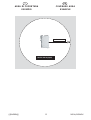
(((ELKRON))) MS04/MS04PK12
AREA DI COPERTURA
ESEMPIO COVERAGE AREA
EXAMPLE
AREA = 48 mq (sqm)
R = 4m

IGB
(((ELKRON))) MS04/MS04PK
1234
2112
+
13
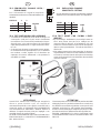
13.3 SENSIBILITA’ CANALE URTO /
ESPLOSIONE
LIVELLO 1 2
1 OFF OFF BASSA
2 OFF ON
3 ON OFF
4 ON ON ALTA
13.4
TEST POINT MISURA LIVELLO SEGNALE
• Connettendo un multimetro od un tester analogico sui
2 test point (vedi par.7.0) può essere visualizzata
una tensione che in assenza di perturbazioni è pros-
sima allo zero, e che sale man mano che il microfono
capta delle perturbazioni. La soglia di allarme è fissa-
ta a 5V.
• Se la tensione misurata sui test-point (senza genera-
re volutamente delle perturbazioni) non si stabilizza
ma continua a salire, significa che il microfono sta
captando del rumore ambientale e che pertanto la
sensibilità va ridotta.
Per il rilevamento di segnali di ampiezza
estremamente elevata ma di durata limitata (non
ripetitivi).
ATTENZIONE
Questi TEST POINT sono concepiti per eseguire la
messa a punto iniziale o per un controllo di
manutenzione periodico; sono perciò accessibili solo a
coperchio aperto ed impiegabili ESCLUSIVAMENTE
con strumentazione alimentata a batteria. Evitare di
utilizzare il segnale dei test point per impieghi o con
modalità diverse da quelle indicate.
LA NON OSSERVANZA DI TALI PRECAUZIONI PUO’
PREGIUDICARE IL CORRETTO FUNZIONAMENTO
DEL DISPOSITIVO.
13.3 EXPLOSION CHANNEL
SENSITIVITY SETTING
LEVEL 1 2
1 OFF OFF LOW
2 OFF ON
3 ON OFF
4 ON ON HIGH
For the detection of signals of extremely elevated
ampleness but of limited duration (not repetitive).
13.4 TEST POINT FOR SIGNAL LEVEL
MESURE
• By connecting a multimeter or an analogic tester on
the 2 tests points (see par.7.0) a voltage can be
measured that in absence of perturbations it is next
to the zero, and it increases as soon as the microphone
detects some perturbations. The alarm threshold is
fixed at 5V.
• If the voltage measured on the test-points (in absence
of perturbations) it doesn't remain stable but continue
to increase, it means that the microphone is detecting
some environmental noise and therefore the sensitivity
must be reduced.
ATTENTION
These test points are conceived both to perform the initial
debugging and for a periodic maintenance control; they
are therefore accessible only with the cover opened and
utilisable exclusively by self supplied instrumentation.
Avoid to use the tests points output for purposes or with
procedures which are different from the specified one
MISSED CONFORMITY TO SUCH CAUTIONS CAN
COMPROMISE THE CORRECT OPERATION OF THE
DEVICE.

IGB
(((ELKRON))) MS04/MS04PK14
14.0 CARATTERISTICHE FUNZIONALI
14.1 CONTROLLO ALIMENTAZIONE
• Il microfono è predisposto per funzionare in un
RANGE compreso tra i 9 Vdc ed i 15 Vdc. Al di fuori
da tali valori il microfono blocca automaticamente il
suo funzionamento con conseguente apertura del
contatto di allarme. Al rientro della tensione di ali-
mentazione (ai valori compresi nel range) il microfo-
no esegue automaticamente la procedura descritta
nella PRIMA ALIMENTAZIONE.
14.2 AUTOTEST
• Ogni 5 minuti il microfono esegue un AUTOTEST
analizzando tutti i circuiti analogici e l’efficienza del
sistema di rilevazione. Una eventuale anomalia de-
termina la commutazione delle uscite di allarme ed il
lampeggio del LED relativo al canale guasto.
14.3 COMANDO REMOTE
• Applicando una tensione 0Vdc sull’ingresso -R il mi-
crofono raddoppia automaticamente il ritardo
(RESPONSE) programmato. In questo modo qualora
fosse posto a protezione di BAMCOMAT è possibile
evitare che si produca un allarme inopportuno a cau-
sa dei disturbi generati dalle operazioni di prelievo
(meccanismo per la stampa) - per tale connessione
occorre estrapolare il segnale dai comandi elettrici del-
l’apparato.
15.0 INST. PERTURBATORE INTERNO
ESEMPIO DI CONNESSIONE CON COMANDO NEGATIVO (-12V)
EXAMPLE OF NEGATIVE CONTROL CONNECTION (-12V)
ALIMENTAZ. MICROFONO
DETECTOR SUPPLY
COMANDO (-12Vdc)
CONTROL (-12Vdc)
PERTURBATORE
PERTURBATOR
ALIMENTAZ. MICROFONO
DETECTOR SUPPLY
COMANDO (+12Vdc)
CONTROL (+12Vdc)
PERTURBATORE
PERTURBATOR
ESEMPIO DI CONNESSIONE CON COMANDO POSITIVO
(+12V)
EXAMPLE OF POSITIVE CONTROL CONNECTION (+12V)
14.0 FUNCTIONAL CHARACTERISTICS
14.1 POWER TEST
• The microphone is set up to work in a RANGE from 9
Vdc to 15 Vdc. Out of this range, the microphone will
automatically stop working and open the alarm con-
tact. When the voltage returns with the specified range,
the microphone will automatically run the procedure
described in FIRST POWER ON.
14.2 SELF-TEST
• The microphone will run a SELF-TEST every five min-
utes, analysing the analogue circuits and the efficiency
of the detection system. Any failures will switch the
alarm outputs and the faulty channel LED will flash.
14.3 REMOTE CONTROL
• The microphone automatically double the programmed
delay (RESPONSE) by applying a voltage of 0Vdc on
the -R input. In this way, when the device is used to
protect an ATM, this prevents generating an inappro-
priate alarm during tilling operations (printing the re-
ceipt). The electrical control signals of the device will
need to be extrapolated for this connection.
15.0 INTERNAL PERTURBATOR
INSTALLATION
A STRUTTURE MURARIE
B STRUTTURE COMPOSITE
C STRUTTURE METALLICHE
A WALL STRUCTURES
B COMPOSITE STRUCTURES
C METALLIC STRUCTURES

IGB
(((ELKRON))) MS04/MS04PK15
16.0 TECHNICAL SPECIFICATIONS
- Nominal power voltage: ...........12V— ± 25%
- Intake: .....................................25 mA typ at 12 V—
30 mA max
- Certified working temperature ... from + 5°C to +40°C
- Working temperature stated by
manufacturer : .........................from -10°C to +70°C
- Heat attack tampering tripping
temperature : ...........................from - 5°C to +60°C
- Heat sensor tripping gradient ..approx. 4°C/min.
- Automatic self test each 5 min
- Alarm tim
e ............................... 4 s approx.
- Measuredband approx. from 10 to 100KHz
- Solid state relay alarm output
- Tamper output for opening, removal, heat attacks
- Alarm and tamper output resistor 35 ohm
- Degree of certified protection: .. IP 3X
- Manufacturer’s declared
degree of protection: ............... IP 54
- Effective floor surface
protected: ................................ 48 sq.m.
- Alarm terminals: ...................... solid state relay
-Tamper terminals protected against:
unauthorized opening; removal; heat attacks
- Maximum current ...................... 0.1 A
- Max voltage contacts ............... 50 V—
- Dimensions (lxhxw) .................
136x48x89 mm
- Weight .....................................550 g
16.0 CARATTERISTICHE TECNICHE
- Tensione nominale di alim. ......... 12 V—
- Tensione min. e max di funz....... 9 -:- 15 V—
- Assorbimento............................. 25 mA typ a 12 V—
30 mA max
- Temp. di funz. certificata ............ +5°C -:- +40°C
- Temp. di funz. dichiarata dal
costruttore ................................. -10°C -:- +70°C
- Temperatura di intervento
manomissione attacchi termici.. -5°C -:- +60°C
- Autotest ciclico automatico ....... ogni 5 minuti
- Livello di prestazione garantito
III° (con MS04IT + MS04ET)
II° (con perturbatore interno MS04IT)
I° (microfono standard)
- Grado di protezione certificato IP3X (CEI 70-1)
- Grado di protezione dichiarato
dal costruttore ........................... IP54
- Tempo di allarme opto di uscita 4s circa
- Rivelazione gradiente termico... 4°C/min. circa
- Banda rilevata da 10 a 100 Khz circa
- Copertura utile........................... 48 mq
- Uscita di allarme ....................... relè allo stato solido
- Uscita tamper per apertura, asportazione, attacchi
termici
- Resist. opto uscite allarme e tamper typ 30 ohm
max 35 ohm
- Corrente max contatti................ 0,1 A
- Tensione max contatti ................ 50 V—
- Dimensioni (lxhxp) .................... 136x48x89 mm
- Peso .......................................... 550 gr.
N.B.: l’esclusione del TAMPER ANTIASPORTAZIONE
mediante il ponticello JP1 comporta il declassamento
al I° livello di prestazione.
PRODOTTI COPERTI DAL MARCHIO IMQ
Microfono selettivo MS04
Microfono selettivo con copritoppa MS04PK
Perturbatore interno MS04IT
Perturbatore esterno MS04ET
Piastra di fissaggio a muro ed a saldare SPA04

IGB
(((ELKRON))) MS04/MS04PK
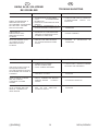
GUIDA ALLA SOLUZIONE
DEI PROBLEMI
PROBLEMA POSSIBILI CAUSE SOLUZIONI
DANDO ALIMENTAZIONE IL
SENSORE NON AVVIA
L’ACCENSIONE SEQUENZIALE
DEI LEDS ED IL SISTEMA
RESTA IN ALLARME
• ALIMENTAZIONE FUORI RANGE
• CAVO ALIMENTAZIONE
INTERROTTO
• MORSETTI ALIMENTAZIONE NON
SERRATI
• IL DC/DC CONVERTER O IL
SISTEMA DI SINTESI SONO GUASTI
• CONTROLLARE CHE LA CORRETTA
ALIMENTAZIONE ARRIVI SUI
MORSETTI
• INVIARE IL PRODOTTO AL
FORNITORE
I LED “P” ED “E”
LAMPEGGIANO ED IL
SENSORE RESTA IN
ALLARME
• ELEMENTO DI CONTATTAZIONE
SENSORE-SCHEDA DIFETTOSO,
OSSIDATO O MANCANTE • PULIRE I CONTATTI
SOLO UNO DEI LED “P” ED
“E” LAMPEGGIA ED IL
SENSORE RESTA IN
ALLARME
• UNO DEI DUE AMPLIFICATORI
O IL SISTEMA DI ANALISI SONO
GUASTI
• INVIARE IL PRODOTTO AL
FORNITORE
PROBLEM POSSIBLE CAUSES SOLUTIONS
THE LEDS DO NOT LIGHT UP
IN SEQUENCE AND THE
SYSTEM REMAINS IN ALARM
MODE WHEN THE SENSOR IS
POWERED
• POWER OUT OF RANGE
• BROKEN POWER WIRE
• LOOSE POWER TERMINALS
• FAULTY DC/DC CONVERTER OR
SYNTHESIS SYSTEM
• CHECK THAT CORRECT POWER
REACHES THE TERMINALS
• SEND THE PRODUCT TO THE
SUPPLIER
LEDS “P” AND “E” FLASHES
AND THE SENSOR
CONTINUES TO SEND
ALARMS
• FAULTY, OXIDATED OR MISSING
SENSOR-BOARD CONTACT
SPRING • CLEAN THE CONTACTS
ONLY ONE LED EITHER “P”
OR “E” FLASHES AND THE
SENSOR CONTINUES TO
SEND ALARMS
• EITHER OF THE AMPLIFIERS
ARE OR THE ANALYSIS
SYSTEM IS FAULTY
• SEND THE PRODUCT TO THE
SUPPLIER
TROUBLESHOOTING
16

IGB
(((ELKRON))) MS04/MS04PK
17.0 COPRITOPPA - CARATTERISTICHE
GENERALI
MS04PK è il microfono selettivo equipaggiato di serie
con dispositivo copritoppa.
Il suo utilizzo, non alterando le caratteristiche originarie
di rilevazione del microfono selettivo MS04, è consentito
nell’ambito della certificazione IMQ - Sistemi di
Sicurezza.
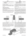
CAMPO DI APPLICAZIONE
E CONNESSIONI ELETTRICHE
Il dispositivo rende non accessibile la toppa della
serratura di sicurezza di armadi blindati o corazzati,
porteforti, casseforti ecc.
L’occlusore meccanico è in grado di ruotare di 180° ed
ha una sola posizione di riposo (che può essere scelta
tra -90°, 0°, +90° - vedi figura) nella quale, tramite un
microswitch, fornisce un contatto elettrico (1A @ 24V)
normalmente chiuso nello stato di toppa occlusa.
Lo sblocco del meccanismo si ottiene premendo
sull’occlusore e ruotandolo.
Un accesso non autorizzato alla serratura determina
pertanto l’apertura della linea NC di controllo, la cui
informazione può essere gestita dalla centrale di allarme
(collegando i due fili del contatto NC ad un ingresso di
centrale dedicato alla segnalazione specifica) o
localmente dal microfono stesso, collegando il contatto
NC in serie al contatto NC ALARM.
POSIZIONE 1
POSITION 1
POSIZIONE 2
POSITION 2
POSIZIONE 3
POSITION 3
AVVERTENZA
L’azionamento ripetuto più volte nella
stessa manovra può mandare in allarme il
microfono (specialmente alle sensibilità più
alte). Limitarsi perciò nelle manovre.
17
17.0 KEYHOLE PROTECTOR- GENERAL
CHARACTERISTICS
The MS04PK is the version of the selective microphone
that comes with a keyhole protector. This version retains
all of the basic characteristics of the selective
microphone MS04. Its use, therefore, will not invalidate
the “IMQ” electrical systems safety certification
trademark coverage.
FIELD OF APPLICATION & ELECTRICAL
CONNECTIONS
This device covers the keyhole of the security lock found
on armored or reinforced security cabinets, strong
doors, vaults, etc. It makes the keyhole inaccessible
except by tampering with it. The mechanical closure
device can be rotated around up to 180° but has only
one resting position. The resting position can be either
0° or ± 90° (see figures on this page: positions 1-3). By
the use of a micro switch, a current of 1 A @ 24V dc is
applied to the closure device. In this state, it is then
part of the closed circuit, which is the normal protected
keyhole position.
The device is unblocked by pressing on it and rotating
the lever (see figure on this page). An unauthorized
access to the lock would thusly open the NC (normally
closed) control line generating an alarm condition. The
information so generated can be managed at the alarm
control unit by connecting the two wires of the NC
terminal to the specific dedicated terminal of the Central
BUS Unit. It can also be locally managed at the selective
microphone by connecting the two wires of the NC
terminal in series with the NC ALARM contact
WARNING!
The same repeated movement
of the keyhole protector over a
short period of time, could
cause it to signal an alarm. This
is especially true when the cut-
off for the keyhole protector’s
selective microphone is set at
lower thresholds.
We recommend that you limit
the movements of the keyhole
protector.

IGB
(((ELKRON))) MS04/MS04PK
A
18.0 INSTALLAZIONE COPRITOPPA
SCELTA DELLA POSIZIONE DI RIPOSO
Per scegliere la posizione di riposo, procedere come
qui di seguito descritto.
- Allentare la vite “A” fino a sbloccare la rotazione della
leva;
- Ruotare l’occlusore scegliendo la posizione
desiderata tra le 3 possibili;
- Riavvitare la vite metrica a croce avendo cura di
serrarla a fondo.
18
18.0 KEYHOLE PROTECTOR
CHOOSING THE “RESTING POSITION”
To choose and set the normal resting position, follow
these instructions (see figures on this page).
-Loosen screw “A”, with a hex screwdriver, until you
are able to freely rotate the lever.
-Rotate the keyhole cover, stopping in one of the 3
possible pre-determined positions.
-Carefully tighten the hex screw until it stops.

IGB
(((ELKRON))) MS04/MS04PK
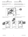
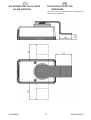
19.0 INGOMBRI DELL’OCCLUSORE
(A LEVA PREMUTA)
19
19.0 KEYHOLE PROTECTOR
DIMENSIONS
(The closure device is pressed down and figures are
expressed in millimeters.)
15

ELKRON S.p.A.
Via Cimarosa, 39 - 10154 Torino (TO)
TEL. +39(0)11.3986711 - FAX +39(0)11.3986790
www.elkron.it e-mail [email protected]
e-mail Assistenza Tecnica [email protected]
CERTIFICAZIONI DI QUALITA' AZIENDALE
La ELKRON S.p.A. si riserva di apportare modifiche/migliorie al presente manuale senza preavviso.
-
 1
1
-
 2
2
-
 3
3
-
 4
4
-
 5
5
-
 6
6
-
 7
7
-
 8
8
-
 9
9
-
 10
10
-
 11
11
-
 12
12
-
 13
13
-
 14
14
-
 15
15
-
 16
16
-
 17
17
-
 18
18
-
 19
19
-
 20
20


Elkron MS04PK Guida d'installazione
- Categoria
- Illuminazione di comodità
- Tipo
- Guida d'installazione
- Questo manuale è adatto anche per
in altre lingue
- English: Elkron MS04PK Installation guide