Documentazione
Tecnica
T60
rev. 0.1
07/2004
©
CAME
CANCELLI AUTOMATICI
RSE
F
319T60-1
SERIE Z | Z SERIES | SERIE Z
ITALIANO / ENGLISH / ESPAÑOL
SCHEDA COMANDO RSE
RSE CONTROL BOARD
TARJETA DE MANDO RSE
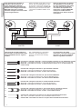
CARATTERISTICHE GENERALI
Prodotto: Progettato e costruito
interamente dalla CAME CANCELLI
AUTOMATICI S.p.a. , rispondente alle
vigenti norme di sicurezza.
Garantita 24 mesi salvo
manomissioni.
Inserendo la scheda seriale RSE
sulle schede ZG5 e si può abilitare la
funzione bussola o abbinato tramite i
dip switch.
Le prestazioni da noi indicate sono
valide solo se il montaggio è stato
eseguito correttamente, secondo le
nostre indicazioni tecniche.
Attenzione: prima di intervenire
all’interno dell’apparecchiatura,
togliere la tensione di linea
SCHEDA GESTIONE FUNZIONI BARRIERE ABBINATE E/O BUSSOLA PER SCHEDA ZG5
BOARD FOR MANAGING THE COMBINED AND/OR INTERLOCK BARRIER FUNCTIONS FOR THE ZG5 BOARD
TARJETA DE GESTIÓN DE LAS FUNCIONES DE LAS BARRERAS COMBINADAS O INTERBLOQUEADAS PARA TARJETA ZG5
GENERAL CHARACTERISTICS
Product: Designed and built entirely by
CAME CANCELLI AUTOMATICI S.p.A.,
in full compliance with current safety
standards.
24-month warranty (rendered void by
tampering).
By inserting the RSE serial board onto
the ZG5 boards, you can use the dip
switches to enable the interlock or com-
bined function.
The declared performances are only
valid if assembly has been performed
according to our technical recommen-
dations.
Caution: before intervening
inside the equipment, ensure the mains
voltage is off.
CARACTERÍSTICAS GENERALES
Producto: Diseñado y fabricado
completamente por CAME CANCELLI
AUTOMATICI S.p.A., responde a las
normas de seguridad vigentes.
Garantía 24 meses salvo alteraciones.
Conectando la tarjeta serial RSE
a la tarjeta ZG5 se puede habilitar,
mediante los dip switches, la
función de barrera interbloqueada o
combinada.
Las prestaciones indicadas son
válidas sólo si el montaje ha sido
efectuado correctamente según
nuestras indicaciones técnicas.
Atención: antes de trabajar
en el interior del equipo, corte la
tensión de la línea

2
3
AF
AF
2
1
ON
OFF
2
1
DIP-SWITCH (1-2)
2
1
ON
OFF
ITALIANO - ENGLISH - ESPAÑOL
ITALIANO - ENGLISH - ESPAÑOL
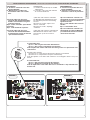
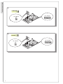
COMPONENTI PRINCIPALI
1-Innesto scheda seriale RSE
(opzionale per collegamento barriere
in abbinato o bussola)
2-Dip-switch funzioni.
SCHEDA SERIALE RSE / RSE SERIAL BOARD / TARJETA SERIAL RSE
SELEZIONI FUNZIONI RSE /
RSE FUNCTION SELECTIONS / SELECCIONES DE LAS FUNCIONES RSE
Dip-Switch RSE:
Inserendo la scheda seriale RSE sulla
scheda ZG5 MASTER si può abilitare
la funzione bussola o abbinato tramite
i dip switch.
MAIN COMPONENTS
1-RSE serial board coupling (optional
for connecting interlock or combined
barriers)
2-Function dip-switches.
RSE dip switch:
By inserting the RSE serial board onto
the ZG5 MASTER board, you can use
the dip switches to enable the interlock or
combined functions.
COMPONENTES PRINCIPALES
1- Conector tarjeta serial RSE
(opcional para la conexión
de barreras en combinadas o
interbloqueadas)
2-Dip-switches funciones.
Dip-Switch RSE:
Conectando la tarjeta serial RSE a
la tarjeta ZG5 MASTER se puede
habilitar, mediante los dip switches, la
función de barrera interbloqueada o
combinada.
ABBINATE
COMBINED
COMBINADAS
BUSSOLA
INTERLOCK
INTERBLOQUEADAS

2
3
1)
2)
2 DX
SLAVE
4)
AF
2 SLAVE
2
1
3
4
5
6
7
8 9 10
O
N
DIP- SWITCH
2
1
O
N
DIP- SWITCH
RSE
GND
BA
ABINATO
D
E+
ENCODER
VB 24 12
0
GND
BA
ABINATO
D
E+
ENCODER
VB 24 12
0
1 SX
MASTER
AF
2
1
O
N
DIP- SWITCH
RSE
1 MASTER
3)
ITALIANO - ENGLISH - ESPAÑOL
ITALIANO - ENGLISH - ESPAÑOL
BARRIERE CON FUNZIONE ABBINATO
BARRIERS WITH COMBINED FUNCTION
BARRERAS CON FUNCIÓN COMBINADA
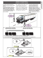
La funzione abbinato permette di
gestire il comando simultaneo di due
barriere.
Inserire su entrambe le barriere la
scheda RSE, collegare le morsettiere
dedicate (ref. 2) per il collegamento
abbinato, posizionare il dip switch
n° 2 in ON della scheda RSE inserita
sulla barriera MASTER e il dip switch
n° 6 e 7 in ON sulla scheda ZG5
barriera SLAVE.
Morsettiera barriera SX MASTER
SX MASTER barrier terminal board
Regleta de conexiones SX MASTER
Morsettiera barriera DX SLAVE
DX SLAVE barrier terminal board
Regleta de conexiones DX SLAVE
NOTA: per la barriera DX vedi collegamento pag. 9-10 della documentazione relativa T41.
NOTE: for the DX barrier, see connection on p. 9-10 of the related documentation T41.
NOTA: para la barrera DX véanse las conexiones de pág. 9-10 de la documentación correspondiente T41.
The combined function allows you to
control two barriers at the same time.
Install the RSE board on both the
barriers, connect the dedicated terminal
boards (ref. 2) for combined connection,
set dip switch no. 2 of the RSE board
installed on the barrier MASTER to ON
and dip switches nos. 6 and 7 to ON on
the SLAVE barrier’s ZG5 board.
La función combinada permite
controlar simultáneamente el
accionamiento de dos barreras.
Conecte en ambas barreras la
tarjeta RSE, conecte las regletas de
conexiones especí cas (ref. 2) para
la conexión combinada, coloque en
ON el dip switch n° 2 de la tarjeta RSE
conectada en la barrera MASTER y
coloque en ON los dip switches n°
6 y 7 en la tarjeta ZG5 en la barrera
SLAVE.

4
5
10
11 E6 E7
TS
1
2
3 4
53P 7
C1
C5
10
11
E6 E7
TS
1
2
3 4
53P 7
C1
C5
MASTER
10-E7
10-E6
SLAVE
10-E6
10-E7
2
3
1
2
2
3P
2
4
2
7
2
C5
ITALIANO - ENGLISH - ESPAÑOL
ITALIANO - ENGLISH - ESPAÑOL
Tutti i dispositivi di comando, di
sicurezza e gli accessori (es. le
cupole lampeggianti delle due
barriere collegate ai morsetti 10-E7)
devono essere collegati alla barriera
MASTER, tranne per il cordone
luminoso collegato sui morsetti 10-E6
di ogni singola barriera.
I dispositivi di comando collegati ai
morsetti della scheda elettronica della
barriera MASTER hanno le seguenti
funzioni:
Pulsante N.C. collegato ai morsetti 1-2 arresta entrambe le barriere (se non utilizzato dip 6 in ON)
Button N.C., connected to terminals 1-2, stops both the barriers (if dip switch 6 is not set to ON)
Botón N.C. conectado a los bornes 1-2 detiene ambas barreras (si no se utiliza el dip 6 se
coloca en ON)
Pulsante N.O. collegato ai morsetti 2-3 apre entrambe le barriere
Button N.O. connected to terminals 2-3 opens both the barriers
Botón N.A. conectado a los bornes 2-3 abre ambas barreras
Pulsante N.O. collegato ai morsetti 2-3P apre la barriera MASTER
Button N.O. connected to terminals 2-3P opens the MASTER barrier
Botón N.A. conectado a los bornes 2-3P abre la barrera MASTER
Pulsante N.O. collegato ai morsetti 2-4 chiude entrambe le barriere
Button N.O. connected to terminals 2-4 closes both the barriers
Botón N.A. conectado a los bornes 2-4 cierra ambas barreras
Pulsante N.O. collegato ai morsetti 2-7 apre-chiude-inverte entrambe le barriere
Button N.O. connected to terminals 2-7 opens-closes-reverses both barriers
Botón N.A. conectado a los bornes 2-7 abre - cierra ambas barreras
Contatto N.O. collegato ai morsetti 2-C5 per chiusura immediata delle barriere.
N.O. contact connected to terminals 2-C5, for immediate barrier closure.
Contacto N.A. conectado a los bornes 2-C5 para cierre inmediato de las barreras.
All the command, safety and accessory
devices (e.g. the ashing domes of the
two barriers connected to terminals 10-
E7) must be connected to the MASTER
barrier except for the ourescent tube
connected on terminals 10-E6 of each
barrier.
The command devices connected to
terminals of the MASTER barrier’s
electronic board have the following
functions:
Todos los dispositivos de mandos,
de seguridad y los accesorios (ej.:
las luces intermitentes tipo cúpula
de la dos barreras conectadas
a los bornes 10-E7) deben estar
conectados a la barrera MASTER,
salvo por el cordón luminoso
conectado en los bornes 10-E6 de
cada barrera.
Los dispositivos de mando
conectados a los bornes de la tarjeta
electrónica de la barrera MASTER
tienen las siguientes funciones:

4
5
U
VW
FC
FA
F
ON
2
1 3 4 5 6 7 8 9
10
EB
EB
VS CT L2T
L1T
INTERBLOCCO
N
L
GND
BA
ABINATO
D
E+
ENCODER
VB 24 12
0
10
11
E6
E7
TS
1
2
3
3P
4
5
7
C1
C5
U
VW
FC
FA
F
ON
2
1 3 4 5 6 7 8 9
10
EB
EB
VS CT L2T
L1T
INTERBLOCCO
N
L
GND
BA
ABINATO
D
E+
ENCODER
VB 24 12
0
10
11
E6
E7
TS
1
2
3
3P
4
5
7
C1
C5
MASTER
RSE
MASTER
ITALIANO - ENGLISH - ESPAÑOL
ITALIANO - ENGLISH - ESPAÑOL
INSTALLAZIONE DEL RADIOCOMANDO - INSTALLING THE RADIO-CONTROL - INSTALACIÓN DEL RADIOMANDO
PROCEDURA
A - Inserire la scheda AF solo sulla
barriera MASTER.
B - Memorizzare la codi ca del
trasmettitore radio sulla scheda
base.
1)Il canale radio CH1 gestisce il
comando delle barriere MASTER e
SLAVE e il trasmettitore esegue la
seguente funzione:
Dip n° 2 OFF- Comando “apre-chiude-
inversione”
Dip n° 2 ON- Comando “apertura”
2)Il canale radio CH2 gestisce il
comando della barriera MASTER e
il radiocomando esegue la funzione
“apre-chiude-inversione”
Il canale radio CH1:
dip n°2 = OFF esegue l’inversione della barriera.
dip n°2 = ON esegue il comando di sola apertura.
N.B. L’impulso del canale radio CH2 non viene gestito se in presenza di una
sola barriera.
The CH1 radio channel:
dip switch no. 2 = OFF reverses the barrier’s direction of movement.
dip switch no. 2 = ON performs the open command only.
N.B. The impulse of the CH2 radio channel is not managed if there is only one
barrier.
El canal radio CH1:
dip n°2 = OFF ejecuta la inversión de la barrera.
dip n°2 = ON ejecuta el mando de sólo apertura.
N.B: El impulso del canal radio CH2 no es controlado si hay montada una
barrera sola.
PROCEDURE
A - Install the AF board only on the MA-
STER barrier.
B - Save the code of the radio transmit-
ter on the motherboard.
1)The CH1 radio channel commands
the MASTER and SLAVE barriers and
the transmitter performs the following
function:
Dip switch no. 2 OFF- “Open-close-
reverse” command
Dip switch no. 2 ON - “Opening”
command
2)The CH2 radio channel commands the
MASTER barrier and the radio-control
performs the “open-close-reverse”
function
PROCEDIMIENTO
A - Conecte la tarjeta AF sólo en la
barrera MASTER.
B - Memorice la codi cación del
transmisor radio en la placa base.
1)El canal radio CH1 controla el ac-
cionamiento de las barreras MASTER
y SLAVE y el transmisor efectúa la
siguiente función:
Dip n° 2 OFF- Mando “abrir-cerrar-in-
versión”
Dip n° 2 ON- Mando “abrir”
2)El canal radio CH2 controla el ac-
cionamiento de la barrera MASTER
y el radiomando efectúa la función
“abrir-cerrar-inversión”

6
7
AF
ON
2
1 3 4 5 6 7 8 9
10
DIP SWITCH (1-10)
ITALIANO - ENGLISH - ESPAÑOL
ITALIANO - ENGLISH - ESPAÑOL
SELEZIONI FUNZIONI /
FUNCTION SELECTIONS
/
SELECCIONES DE LAS FUNCIONES.
1 ON Funzione chiusura automatica
attivata; (1 OFF-disattivata)(da
abilitare solo sulla barriera
MASTER);
2 ON Funzione "apre" con trasmettitore
radio (scheda AF inserita)
attivato(da abilitare solo sulla
barriera MASTER);
2 OFF Funzione "apre-chiude-inversione"
con pulsante (2-7) e trasmettitore
radio (scheda AF inserita)
attivato(da abilitare solo sulla
barriera MASTER);
3 ON Funzione ad "azione mantenuta"
(esclude la funzione del
trasmettitore radio) attivato; (3
OFF disattivato)(da abilitare solo
sulla barriera MASTER);
4 ON Prelampeggio in apertura e in
chiusura attivato, con dispositivo
collegato sui morsetti 10- E7 (4
OFF disattivato)(da abilitare solo
sulla barriera MASTER);
5 ON Rilevazione ostacolo. A motore
fermo (barriera chiusa, aperta o
dopo un comando di stop totale),
impedisce qualsiasi movimento
se i dispositivi di sicurezza (es.
fotocellule) rilevano un ostacolo
(5 OFF disabilitato)(da abilitare
solo sulla barriera MASTER);
6 OFF Funzione di stop totale (collegare
pulsante su 1-2) attivato;(se non
utilizzato posizionare il dip in ON);
7 OFF Funzione di riapertura in fase di
chiusura (collegare i dispositivi
di sicurezza sui morsetti 2-
C1) attivata; (se non utilizzato
posizionare il dip in ON);
8 ON Funzione del test di sicurezza
per la veri ca dell’ef cienza delle
fotocellule (pag. 6) attivato; (8 OFF
disattivata).
9 OFF Encoder attivato per la gestione
dei rallentamenti in apertura e
chiusura degli ostacoli (9 ON
disattivato);
10 Non utilizzato
1 ON Automatic closing function
enabled; (1 OFF-disabled)(to be
enabled only on the MASTER
barrier);
2 ON “Open” function with radio
transmitter (AF board inserted)
enabled(to be enabled only on
the MASTER barrier);
2 OFF Function “open-close-reverse”
with pushbutton (2-7) and radio
transmitter (AF board inserted)
enabled(to be enabled only on
the MASTER barrier);
3 ON “Maintained action” function
(excludes the radio transmitter)
enabled; (3 OFF disabled)(to be
enabled only on the MASTER
barrier);
4 ON Pre- ashing while opening and
closing enabled, with device
connected to terminals 10-E7 (4
OFF disabled)(to be enabled only
on the MASTER barrier);
5 ON Obstacle detection. With motor
not running (barrier closed, open
or after a total-stop command),
all movement is prevented if the
safety devices (e.g. photoelectric
cells) detect an obstacle (5 OFF
disabled)(to be enabled only on
the MASTER barrier);
6 OFF Total-stop function (connect
pushbutton to 1-2) enabled; (if not
used, set dip-switch to ON);
7 OFF Re-opening during closure func-
tion (connect the safety devices
to terminals 2-C1) enabled; (if not
used, set dip-switch to ON);
8 ON Safety test function to check
photoelectric cell ef ciency (page
6) enabled; (8 OFF disabled).
9 OFF Encoder enabled for managing
obstacle slow-downs during ope-
ning and closing (9 ON disabled);
10 Not used
1 ON Función cierre automático
activa; (1 OFF-desactivada)(se
habilita sólo en la barrera
MASTER);
2 ON Función “abrir” con transmisor
radio (tarjeta AF conectada)
activa (se habilita sólo en la
barrera MASTER);
2 ON Función “abrir- cerrar- inver-
sión” con botón (2-7) y trans-
misor radio (tarjeta AF conec-
tada) activa (se habilita sólo en
la barrera MASTER);
3 ON Función “accionamiento con-
tinuo” (excluye la función del
transmisor radio) activa (3 OFF
desactivada) (habilitar sólo en
la barrera MASTER);
4 ON Predestello en apertura y en
cierre activo , con dispositivo
conectado en los bornes10- E7
(4 OFF desactivada) (se habili-
ta sólo en la barrera MASTER);
5 ON- Detección de obstáculos. Con
el motor detenido (barrera
cerrada, abierta o después de
un mando de parada total), im-
pide cualquier movimiento si
los dispositivos de seguridad
(por. ej. fotocélulas) detectan
un obstáculo (5 OFF deshabi-
litada) (se habilita sólo en la
barrera MASTER);
6 OFF Función de parada total (co-
necte el botón en 1-2) activa;
(si no se utiliza, coloque el dip
en ON);
7 OFF Función de apertura durante
el cierre (conecte los dispositi-
vos de seguridad a los bornes
2-C1) activa; (si no se utiliza,
coloque el dip en ON);
8 ON Función del test de seguridad
para el control del funciona-
miento de las fotocélulas (pág.
6) activa; (8 OFF desactivada).
9 OFF Encoder activo para la ges-
tión de las desaceleraciones
durante la apertura y el cierre
en el caso de detección de
obstáculos (9 ON desactivada);
10 No utilizado

6
7
2)
GND
BA
ABINATO
D
E+
ENCODER
VB 24 12
0
GND
BA
ABINATO
D
E+
ENCODER
VB 24 12
0
1)
1
MASTER
2
SLAVE
ITALIANO - ENGLISH - ESPAÑOL
ITALIANO - ENGLISH - ESPAÑOL
BARRIERE CON FUNZIONE BUSSOLA
BARRIERS WITH INTERLOCK FUNCTION
BARRERAS CON FUNCIÓN INTERBLOQUEADA
Inserire su entrambe le barriere la
scheda RSE, collegare le morsettiere
dedicate per il collegamento
abbinato, posizionare il dip switch
n° 1 in ON della scheda RSE inserita
sulla barriera MASTER e il dip switch
n° 6 in ON sulla scheda ZG5 barriera
SLAVE.
N.B. Per ottenere dopo il ciclo
completo di apertura e chiusura di
una barriera, l’apertura automatica
dell’altra barriera.
Posizionare il dip switch n° 2 in ON
della barriera MASTER.
La funzione BUSSOLA mantiene
bloccata la barriera MASTER no
a quando la barriera SLAVE è in
movimento e viceversa.
Install the RSE board on both the
barriers, connect the dedicated terminal
boards for the combined connection,
set dip switch no. 1 on the RSE board
installed on the MASTER barrier to ON,
and set dip switch no. 6 on the SLAVE
barrier’s ZG5 board to ON.
N.B. To automatically open the other
barrier after the complete barrier
opening and closure cycle,
set dip switch no. 2 of the MASTER
barrier to ON.
The INTERLOCK function keeps the
MASTER barrier locked while the
SLAVE barrier is moving and vice versa.
Conecte en ambas barreras la
tarjeta RSE, conecte las regletas de
conexiones especí cas (ref. 2) para
la conexión combinada, coloque en
ON el dip switch n° 1 de la tarjeta RSE
conectada en la barrera MASTER, y
coloque en ON el dip switch n° 6 en
la tarjeta ZG5 de la barrera SLAVE.
N.B. Para obtener después del ciclo
completo de apertura y cierre de una
barrera, la apertura automática de la
otra barrera.
Coloque en ON el dip switch n° 2 de
la barrera MASTER.
La función INTERBLOQUEADA
mantiene bloqueada la barrera
MASTER mientras la barrera SLAVE
esté en movimiento y viceversa.
Morsettiera barriera SX MASTER
SX MASTER barrier terminal board
Regleta de conexiones SX MASTER
Morsettiera barriera DX SLAVE
DX SLAVE barrier terminal board
Regleta de conexiones DX SLAVE
NOTA: per la barriera DX vedi collegamento pag. 9-10 della documentazione relativa T41.
NOTE: for the DX barrier, see connection on p. 9-10 of the related documentation T41.
NOTA: para la barrera DX véanse las conexiones de pág. 9-10 de la documentación correspondiente T41.
La pagina si sta caricando...

8
9
10
11 E6 E7
TS
1
2
3 4
53P 7
C1
C5
10
11
E6 E7
TS
1
2
3 4
53P 7
C1
C5
MASTER
10-E7
10-E6
10-E7
10-E6
SLAVE
2-C1
2-C5
2-C1
2-C5
Esempio :
ITALIANO - ENGLISH - ESPAÑOL
ITALIANO - ENGLISH - ESPAÑOL
Tutti i dispositivi di comando
devono essere collegati alla
barriera MASTER, mentre per ogni
barriera effettuare i collegamenti del
dispositivo di sicurezza collegato
ai morsetti 2-C1 (es. fotocellula con
funzione di riapertura), del dispositivo
(es. spira magnetica) collegato ai
morsetti 2-C5 (chiusura immediata) e
degli accessori di segnalazione (es.
lampeggiatore a cupola e cordone
luminoso).
Per aprire entrambe le barriere,
azionare il dispositivo di comando
collegato ai morsetti 2-3, a barriera
aperta azionare il dispositivo
di sicurezza (pulsante di stop
obbligatotio) collegato ai morsetti 1-2
e azionare il dispositivo di comando
collegato ai morsetti 2-3P per aprire
la seconda barriera.
In caso di emergenza se si
aziona manualmente lo sblocco
del motoriduttore con chiave e si
posiziona in apertura una barriera
l’altra viene disinibita.
All the command devices must be
connected to the MASTER barrier, while
for all barriers perform the connections
of the safety device connected to
terminals 2-C1 (e.g. photoelectric cell
with re-opening function), the device
(e.g. magnetic coil) connected to
terminals 2-C5 (immediate closure)
and of the signalling accessories (e.g.
ashing dome lamp and ourescent
tube).
To open both the barriers, activate the
command device connected to terminals
2-3, with the barrier open, activate the
safety device (compulsory stop button)
connected to terminals 1-2 and run the
command device connected to terminals
2-3P to open the second barrier.
In the event of an emergency if you
manually release the gearmotor using
a key and move a barrier to its open
position, the other one is released.
Todos los dispositivos de mando
deben conectarse a la barrera
MASTER, mientras que para
cada barrera hay que conectar el
dispositivo de seguridad conectado
a los bornes 2-C1 (ej.: fotocélula con
función de apertura), del dispositivo
(por ej. lazo magnético) conectado a
los bornes 2-C5 (cierre inmediato) y
de los accesorios de señalización (ej.
luz intermitente tipo cúpula y cordón
luminoso).
Para abrir ambas barreras, accione
el dispositivo de mando conectado a
los bornes 2-3, con la barrera abierta
accione el dispositivo de seguridad
(botón de parada obligatoria)
conectado a los bornes 1-2 y accione
el dispositivo de mando conectado a
los bornes 2-3P para abrir la segunda
barrera.
En caso de emergencia si se acciona
manualmente el desbloqueo del
motorreductor con llave y se abre
una barrera, la otra se dishinibe.
La pagina si sta caricando...

10
11
U
VW
FC
FA
F
ON
2
1 3 4 5 6 7 8 9
10
EB
EB
VS CT L2T
L1T
INTERBLOCCO
N
L
GND
BA
ABINATO
D
E+
ENCODER
VB 24 12
0
10
11
E6
E7
TS
1
2
3
3P
4
5
7
C1
C5
U
VW
FC
FA
F
ON
2
1 3 4 5 6 7 8 9
10
EB
EB
VS CT L2T
L1T
INTERBLOCCO
N
L
GND
BA
ABINATO
D
E+
ENCODER
VB 24 12
0
10
11
E6
E7
TS
1
2
3
3P
4
5
7
C1
C5
MASTER
RSE
SLAVE
ITALIANO - ENGLISH - ESPAÑOL
ITALIANO - ENGLISH - ESPAÑOL
INSTALLAZIONE DEL RADIOCOMANDO - RADIO CONTROL INSTALLATION - INSTALACIÓN DEL RADIOMANDO
PROCEDURA
A - Inserire la scheda AF solo sulla
barriera MASTER.
B - Memorizzare la codi ca sulla
scheda.
1)Il canale radio CH1 comanda la
barriera MASTER e il trasmettitore
esegue la seguente funzione:
Dip n° 2 OFF- Comando “apre-chiude-
inversione”
Dip n° 2 ON- Comando “apertura”
2)Il canale radio CH2 comanda la
barriera SLAVE e il trasmettitore
esegue la seguente funzione:
Dip n° 2 in OFF- Comando “apre-
chiude-inversione”
Dip n° 2 in ON- Comando “apertura”
N.B. L’impulso del canale radio CH2
non viene gestito se in presenza di
una sola barriera.
1)The CH1 radio channel commands
the MASTER barrier and the transmitter
performs the following function:
Dip switch no. 2 OFF- “Open-close-re-
verse” command
Dip switch no. 2 ON - “Opening” com-
mand
2)The CH2 radio channel commands the
SLAVE barrier and the transmitter per-
forms the following function:
Dip switch no. 2 OFF- “Open-close-re-
verse” command
Dip switch no. 2 ON- “Opening” com-
mand
N.B. The impulse of the CH2 radio
channel is not managed if there is only
one barrier.
1)El canal radio CH1 acciona la
barrera MASTER y el transmisor
efectúa la siguiente función:
Dip n° 2 OFF- Mando “abrir-cerrar-
inversión”
Dip n° 2 ON- Mando “abrir”
2)El canal radio CH2 acciona la
barrera SLAVE y el transmisor
efectúa la siguiente función:
Dip n° 2 OFF- Mando “abrir-cerrar-
inversión”
Dip n° 2 ON- Mando “abrir”
N.B: El impulso del canal radio CH2
no es controlado si hay montada una
barrera sola.
PROCEDURE
A - Install the AF board only on the MA-
STER barrier.
B - Save the code of the radio transmit-
ter on the motherboard.
PROCEDIMIENTO
A - Conecte la tarjeta AF sólo en la
barrera MASTER.
B - Memorice la codi cación del
transmisor radio en la placa base.

CAME LOMBARDIA S.R.L._____COLOGNO M. (MI)
(+39) 02 26708293 (+39) 02 25490288
CAME SUD S.R.L. ___________________NAPOLI
(+39) 081 7524455 (+39) 081 7529109
CAME (AMERICA) L.L.C.________MIAMI (FL)
(+1) 305 5938798 (+1) 305 5939823
CAME AUTOMATISMOS S.A__________MADRID
(+34) 091 5285009 (+34) 091 4685442
CAME BELGIUM__________________LESSINES
(+32) 068 333014 (+32) 068 338019
CAME FRANCE S.A.____NANTERRE CEDEX (PARIS)
(+33) 01 46130505 (+33) 01 46130500
CAME GMBH________KORNTAL BEI (STUTTGART)
(+49) 07 15037830 (+49) 07 150378383
CAME GMBH ____________SEEFELD BEI (BERLIN)
(+49) 03 33988390 (+49) 03 339885508
CAME PL SP.ZO.O______________WARSZAWA
(+48) 022 8365076 (+48) 022 8369920
CAME UNITED KINGDOM LTD___NOTTINGHAM
(+44) 0115 9210430 (+44) 0115 9210431
CAME CANCELLI AUTOMATICI S.P.A.
DOSSON DI CASIER (TREVISO)
(+39) 0422 4940 (+39) 0422 4941
SISTEMA QUALITÅ
CERTIFICATO
ASSISTENZA TECNICA
NUMERO VERDE
800 295830
WEB
www.came.it
E-MAIL
Documentazione
Tecnica
T60
rev. 0.1
07/2004
©
CAME
CANCELLI AUTOMATICI
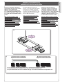
RSE
AF
ON
2
1 3 4 5 6 7 8 9
10
DIP SWITCH (1-10)
Tut ti i dati sono sta ti con trol la ti con la mas si ma cura. Non ci
as su mia mo co mun que al cu na re spon sa bi li tà per even tua li errori
od omissioni.
All data checked with the maximum care. However, no liability is accepted
for any error or omission.
Todos los datos se han controlado con la máxima atención.
No obstante no nos responsabilizamos de los posibles errores
u omisiones.
319T60-1
SERIE Z | Z SERIES | SERIE Z
ITALIANO / ENGLISH / ESPAÑOL
SCHEDA COMANDO RSE
RSE CONTROL BOARD
TARJETA DE MANDO RSE
SELEZIONI FUNZIONI / FUNCTION SELECTIONS / SELECCIONES DE LAS FUNCIONES
1 ON “Automatic closing” function
enabled; (1 OFF-disabled) (to be
enabled on both barriers);
2 OFF “Open-close-reverse” function
with pushbutton (2-7) and radio
transmitter activated (to be ena-
bled only on MASTER barrier);
3 ON “Maintained action” function ena-
bled (excludes the radio transmit-
ter function); (3 OFF disabled)(to
be enabled only on MASTER
barrier);
4 ON Pre- ashing while opening and
closing enabled, with device
connected on terminals 10- E7 (4
OFF disabled)
5 ON Obstacle detection. With motor
not running (barrier closed, open
or after a total stop command),
any movement is prevented if the
safety devices (e.g. photoelectric
cells) detect an obstacle (5 OFF
disabled)(to be enabled only on
MASTER barrier);
6 OFF Total-stop function (connect
pushbutton to 1-2) enabled; (if not
used, set dip-switch to ON);
7 OFF Re-opening function during clo-
sure (connect the safety devices
on terminals
2-C1) enabled; (if not used, set
dip-switch to ON);
8 ON Safety test function to check
photoelectric cell ef ciency (p. 6)
enabled; (8 OFF disabled).
9 OFF Encoder enabled for managing
obstacle slow-downs during ope-
ning and closing (9 ON disabled);
10 Not used
1 ON Función”cerrar automático”
activa; (1 OFF-desactivada) (se
habilita en ambas barreras);
2 OFF Función “abrir- cerrar- inver-
sión” con botón (2-7) y trans-
misor radio activa (se habilita
sólo en la barrera MASTER);
3 ON Función “accionamiento con-
tinuo” (excluye la función del
transmisor radio) activa (3 OFF
desactivada) (se habilita sólo
en la barrera MASTER);
4 ON Predestello durante la aper-
tura y cierre activa, con dispo-
sitivo conectado a los bornes
10- E7 (4 OFF desactivada);
5 ON- Detección de obstáculos. Con
el motor detenido (barrera
cerrada, abierta o después de
un mando de parada total), im-
pide cualquier movimiento si
los dispositivos de seguridad
(por. ej. fotocélulas) detectan
un obstáculo (5 OFF deshabi-
litada) (se habilita sólo en la
barrera MASTER);
6 OFF Función de parada total (co-
necte el botón en 1-2) activa;
(si no se utiliza, coloque el dip
en ON);
7 OFF Función de apertura durante
el cierre (conecte los dispositi-
vos de seguridad a los bornes
2-C1) activa; (si no se utiliza,
coloque el dip en ON);
8 ON Función del test de seguridad
para el control del funciona-
miento de las fotocélulas (pág.
6) activa; (8 OFF desactivada).
9 OFF Encoder activo para la ges-
tión de las desaceleraciones
durante la apertura y cierre en
el caso de detección de obstá-
culos (9 ON desactivada);
10 No utilizado
1 ON Funzione “chiusura automati-
ca” attivata; (1 OFF-disattivata)
(da abilitare su entrambe le
barriere);
2 OFF Funzione “apre-chiude-inver-
sione” con pulsante (2-7) e
trasmettitore radio attivato(da
abilitare solo sulla barriera
MASTER);
3 ON Funzione ad “azione mante-
nuta” (esclude la funzione del
trasmettitore radio) attivato;
(3 OFF disattivato)(da abilitare
solo sulla barriera MASTER);
4 ON Prelampeggio in apertura e in
chiusura attivato, con dispositi-
vo collegato sui morsetti 10- E7
(4 OFF disattivato)
5 ON Rilevazione ostacolo. A motore
fermo (barriera chiusa, aperta
o dopo un comando di stop
totale), impedisce qualsiasi
movimento se i dispositivi
di sicurezza (es. fotocellule)
rilevano un ostacolo (5 OFF
disabilitato)(da abilitare solo
sulla barriera MASTER);
6 OFF Funzione di stop totale
(collegare pulsante su 1-2)
attivato;(se non utilizzato posi-
zionare il dip in ON);
7 OFF Funzione di riapertura in fase di
chiusura (collegare i dispositivi
di sicurezza sui morsetti
2-C1) attivata; (se non utilizzato
posizionare il dip in ON);
8 ON Funzione del test di sicurezza
per la veri ca dell’ef cienza
delle fotocellule (pag. 6) attiva-
to; (8 OFF disattivata).
9 OFF Encoder attivato per la gestio-
ne dei rallentamenti in apertura
e chiusura degli ostacoli (9 ON
disattivato);
10 Non utilizzato
-
 1
1
-
 2
2
-
 3
3
-
 4
4
-
 5
5
-
 6
6
-
 7
7
-
 8
8
-
 9
9
-
 10
10
-
 11
11
-
 12
12


in altre lingue
- English: CAME RSE Owner's manual
- español: CAME RSE El manual del propietario
Documenti correlati
-
CAME Z Series Manuale utente
-
CAME G4000 Manuale del proprietario
-
-
CAME G4040IE Manuale utente
-
-
-
-
-
CAME G02801 Manuale del proprietario
-