
O P E R A T I N G I N S T R U C T I O N S
WTL16 - WTS16 Bluetooth®


Described product
WTL16, WTS16 - Bluetooth®
Manufacturer
SICK AG
Erwin-Sick-Str. 1
79183 Waldkirch
Germany
Legal information
This work is protected by copyright. Any rights derived from the copyright shall be
reserved for SICK AG. Reproduction of this document or parts of this document is only
permissible within the limits of the legal determination of Copyright Law. Any modifica‐
tion, abridgment or translation of this document is prohibited without the express writ‐
ten permission of SICK AG.
The trademarks stated in this document are the property of their respective owner.
© SICK AG. All rights reserved.
Original document
This document is an original document of SICK AG.
2
8022692.10DR | SICK
Subject to change without notice

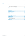
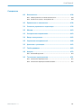
Contents
1 Safety information............................................................................ 4
1.1 General safety notes................................................................................ 4
1.2 Notes on UL approval............................................................................... 4
2 Intended use...................................................................................... 4
3 Operating and status indicators...................................................... 4
4 Mounting............................................................................................. 6
5 Electrical installation........................................................................ 6
6 Commissioning.................................................................................. 7
7 Troubleshooting................................................................................. 14
8 Disassembly and disposal............................................................... 15
9 Maintenance...................................................................................... 15
10 Approvals............................................................................................ 16
10.1 Bluetooth® approvals............................................................................... 16
11 Technical data.................................................................................... 17
11.1 Technical data........................................................................................... 17
11.2 Bluetooth technical data®....................................................................... 17
CONTENTS
8022692.10DR | SICK
Subject to change without notice
3

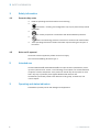
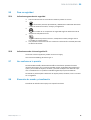
1 Safety information
1.1 General safety notes
■
Read the operating instructions before commissioning.
■
Connection, mounting, and configuration may only be performed by trained
specialists.
■
2006/42/EC
NO
SAFETY
Not a safety component in accordance with the EU Machinery Directive.
■
When commissioning, protect the device from moisture and contamination.
■
These operating instructions contain information required during the life cycle of
the sensor.
1.2 Notes on UL approval
The device must be supplied by a Class 2 source of supply.
UL Environmental Rating: Enclosure type 1
2 Intended use
The WTL16 Bluetooth®, WTS16 Bluetooth® is an opto-electronic photoelectric proxim‐
ity sensor (referred to as “sensor” in the following) for the optical, non-contact detection
of objects, animals, and persons. If the product is used for any other purpose or modi‐
fied in any way, any warranty claim against SICK AG shall become void.
The WTS16 is particularly suited to the detection of flat, glossy, contrast-rich, and
uneven objects.
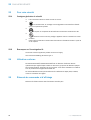
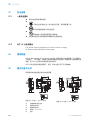
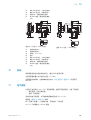
3 Operating and status indicators
Photoelectric proximity sensor with background suppression.
1 SAFETY INFORMATION
4
8022692.10DR | SICK
Subject to change without notice

20
Ø 12,9
Ø 4,1
39,9
55,4
45,5
5
42
29,9
6
3
6,5
15
27,8
7,7
7,8
7,2
35,5
4,1
16
8,3
55,7
5
4
89
16
18,5
3
2
1
6
7
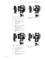
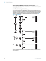
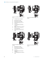
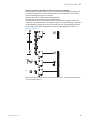
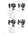
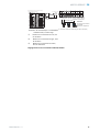
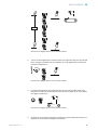
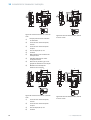
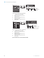
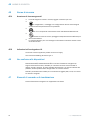
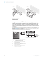
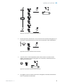
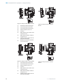
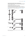
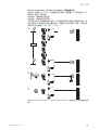
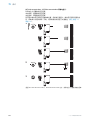
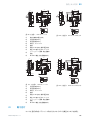
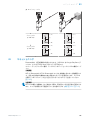
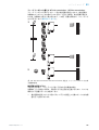
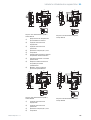
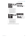
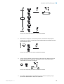
Figure 1: Dimensional drawing 1, WTL16
cable
1
Preferred direction of the target
object
2
Center of optical axis, sender
3
Center of optical axis, receiver
4
Fixing hole, Ø 4.1 mm
5
Connection
6
LED indicator green: Supply voltage
active
7
LED indicator yellow: Status of
received light beam
8
Press-turn element: Adjusting the
sensing range
9
BluePilot blue: Sensing range dis‐
play
20
M12
18
Ø 4,1
39,9
55,4
55,7
45,5
5
7
42
29,9
52,9
6
17,5
3
6,5
15
28
7,5
35,5
4,1
5
4
16
16 18,5
3
2
1
89
6
7
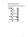
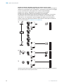
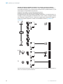
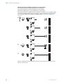
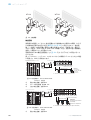
Figure 2: Dimensional drawing 2, WTL16
male connector
Ø 4,1
39,9
55,4
45,5
5
42
29,9
6
3
6,5
15
27,8
7,7
7,8
7,2
35,5
4,1
16
55,7
4
3
12,2
12,2
1
2
2
20
24,2
Ø 12,9
8,3
78
5
6
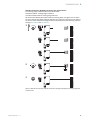
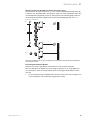
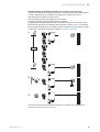
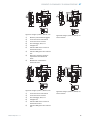
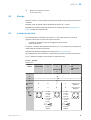
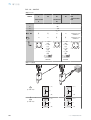
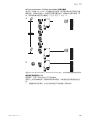
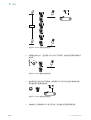
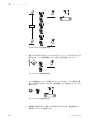
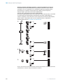
Figure 3: Dimensional drawing 3, WTS16
cable
1
Center of optical axis, sender
2
Center of optical axis, receiver
3
Fixing hole, Ø 4.1 mm
4
Connection
5
LED indicator green: Supply voltage
active
6
LED indicator yellow: Status of
received light beam
M12
12,2
12,2
4
3
1
2
2
17,5
Ø 4,1
7
39,9
55,4
55,7
45,5
5
29,9
52,9
6)
3
6,5
15
28
7,5
35,5
4,1
42
20
18
24,2
16
78
5
6
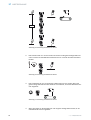
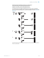
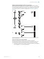
Figure 4: Dimensional drawing 1, WTS16
male connector
OPERATING AND STATUS INDICATORS 3
8022692.10DR | SICK
Subject to change without notice
5

7
Press-turn element: Adjusting the
sensing range
8
BluePilot blue: Sensing range dis‐
play
4 Mounting
Mount the sensor using a suitable mounting bracket (see the SICK range of acces‐
sories).
Note the sensor’s maximum permissible tightening torque of < 1,3 Nm.
Note the preferred direction of the object relative to the sensor, see figure 1, figure 2
(only applies to WTL16).
5 Electrical installation
The sensors must be connected in a voltage-free state (U
V
= 0 V). The following informa‐
tion must be observed, depending on the connection type:
– Male connector connection: Note pin assignment.
– Cable: wire color
Only apply voltage/switch on the voltage supply (U
V
> 0 V) once all electrical connec‐
tions have been established.
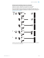
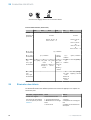
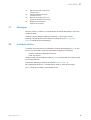
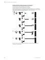
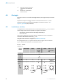
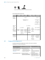
Explanations of the connection diagram (table 1, table 2).
MF (pin 2 configuration) = external input, teach-in, switching signal
Q
L1
/C = switching output, IO-Link communication
DC: 10 ... 30 V DC
Table 1: DC
WTL16
WTS16
-24161xxxA00
-34161xxxA00
-1x161xxxA0
0
-24162xxxA0
0
-34162xxxA0
0
-1x162xxxA0
0
-2416xxxxA01-
A99
-3416xxxxA01-
A99
1 + (L+)
2 MF
3 - (M)
4 Q
L1
/C
Default: MF
Q Q
Q Q www.sick.com
8020347
Default:
Q
L1
/C
Q Q
Q Q
www.sick.com
8020347
1
2
4 3
1 = brn
2 = wht
3 = blu
4 = blk
0.14 mm
2
AWG26
1
2
4 3
1 = brn
2 = wht
3 = blu
4 = blk
0.14 mm
2
AWG26
1
2
4 3
4 MOUNTING
6
8022692.10DR | SICK
Subject to change without notice

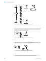
Table 2: Push / pull
Q
Push-pull
(≤ 100 mA)
+ (L+)
Q
‒ (M)
+ (L+)
Q
‒ (M)
Q
Push-pull
(≤ 100 mA)
+ (L+)
Q
‒ (M)
+ (L+)
Q
‒ (M)
6 Commissioning
Bluetooth® is switched on for initial commissioning. You can get SOPASair in the Google
PlayStore (Android) and in the App Store (iOS).
Operating system requirements: Android version 6.0, most current version of iOS.
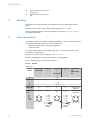
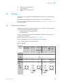
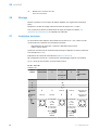
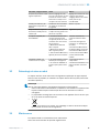
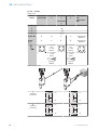
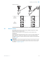
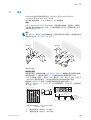
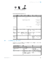
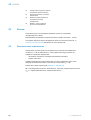
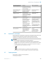
Alignment
WTL16 Bluetooth®, WTS16 Bluetooth®: Align sensor on object. Select the position so
that the red emitted light beam hits the center of the object. You must ensure that the
optical opening (front screen) of the sensor is completely clear [figure 5].
NOTE
For WTS16: If the objects are detected from above, we recommend installing the sen‐
sor at an angle in order to prevent total reflection by a reflective surface, see figure 11,
figure 14.
COMMISSIONING 6
8022692.10DR | SICK
Subject to change without notice
7

WTL16 WTS16
Figure 5: Alignment
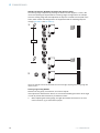
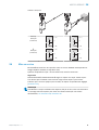
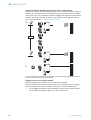
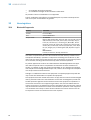
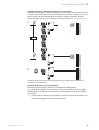
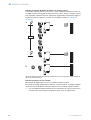
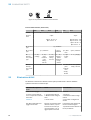
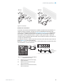
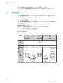
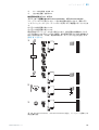
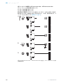
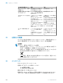
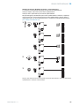
Sensing range
Check the application conditions: Adjust the sensing range and distance to the object
or background and the remission capability of the object according to the correspond‐
ing diagram [see figure 6 and figure 7] (x = sensing range, y = minimum distance
between set sensing range and background (white 90%)). Remission: 6% = black 1,
18% = gray 2, 90% = white 3 (referring to standard white as per DIN 5033). We rec‐
ommend making the adjustments using an object with a low remission.
The minimum distance (= y) for background suppression can be determined from dia‐
gram [figure 61] as follows:
Example: x = 200 mm, y = 15 mm. That is, the background (white, 90%) is suppressed
at a distance of > 15 mm from the sensor.
0
10
5
35
30
25
20
15
45
40
50
100
(3.94)
200
(7.87)
300
(11.81)
600
(23.62)
400
(15.75)
500
(19.69)
0
Distance in mm (inch)
1
2
3
WTL16P-xxxxx1xx
18%/90%
6%/90%
90%/90%
Minimum distance in mm (y) between the set sensing
range and background (white, 90%)
y
x
yx
white background (90%)
Example:
Sensing range on black, 6%,
x = 200 mm, y = 15 mm
Figure 6: Characteristic line 1, WTL16 Blue‐
tooth®-xxxxx1xx, red light
1
Sensing range on black, 6% remission
2
Sensing range on gray, 18% remission
3
Sensing range on white, 90% remission
100
(3.94)
200
(7.87)
Adjustment range
Distance in mm (inch)
A
300
(11.81)
400
(15.75)
500
(19.69)
0
1
2
3
50 300
25 400
10
500
BluePilot:
Sensing range
indicator (blue LED)
Teach-Turn
adjustment
A = Detection distance (depending on object remission)
100
100
100
6 COMMISSIONING
8
8022692.10DR | SICK
Subject to change without notice

0
20
10
60
50
40
30
80
70
90
200
(7.87)
400
(15.75)
600
(23.62)
1,000
(39.37)
800
(31.5)
0
1
2
3
WTS16P-xxxxx1xx
18%/90%
6%/90%
90%/90%
y
x
yx
Minimum distance in mm (y) between the set sensing
range and background (white, 90%)
white background (90%)
Example:
Sensing range on black, 6%,
x = 300 mm, y = 20 mm
Distance in mm (inch)
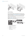
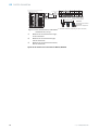
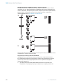
Figure 7: Characteristic line 1, WTS16 Blue‐
tooth®-xxxxx1xx, red light
1
Sensing range on black, 6% remission
2
Sensing range on gray, 18% remission
3
Sensing range on white, 90% remission
100
(3.94)
400
(15.75)
200
(7.87)
A
800
(31.5)
1,000
(39.37)
1,500
(59.06)
0
1
2
3
400
10 500
10
750
BluePilot:
Adjustment range
Distance in mm (inch)
Sensing range indicator
(blue LED)
Teach-Turn adjustment
A = Detection distance (depending on object remission)
100
100
10015
Sensing range setting WTL16, WTS16
COMMISSIONING 6
8022692.10DR | SICK
Subject to change without notice
9

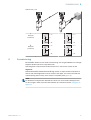
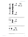
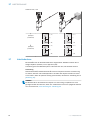
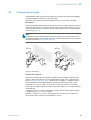
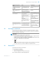
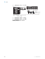
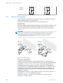
WTL16x-xxxxxx2xAxx, WTS16x-xxxxxx2xAxx with press-turn element:
The sensing range is adjusted by pressing the teach-in button (approx. 1-3 sec.).
Depending on the requirements, the potentiometer can be used for fine-tuning (without
pressing the teach-in button).
Clockwise rotation: sensing range increased.
Counterclockwise rotation: sensing range reduced.
The sensing range can also be adjusted using just the potentiometer. We recommend
placing the object within the sensing range, see figure 8 for an example. Once the sens‐
ing range has been adjusted, the object is removed from the path of the beam, which
causes the background to be suppressed and the switching output to change (see
table 1 and see table 2).
1...3 sec.
1
2
3
Figure 8: WTL16x-xxxxxx2xAxx, WTS16x-xxxxxx2xAxx red light, adjusting the sensing range with
press-turn element
6
COMMISSIONING
10
8022692.10DR | SICK
Subject to change without notice

WTL16x-xxxxxx1xAxx, WTS16x-xxxxxx1xAxx with potentiometer:
The sensing range is adjusted with the potentiometer.
Clockwise rotation: sensing range increased.
Counterclockwise rotation: sensing range reduced.
We recommend placing the object within the sensing range, see figure 9 for an exam‐
ple. Once the sensing range has been adjusted, the object is removed from the path of
the beam, which causes the background to be suppressed and the switching output to
change (see table 1 and see table 2).
1
2
3
Figure 9: WTL16x-xxxxxx1xAxx, WTS16x-xxxxxx1xAxx red light, adjusting the sensing range with
potentiometer
COMMISSIONING
6
8022692.10DR | SICK
Subject to change without notice
11

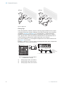
WTL16x-xxxxxx3xAxx, WTS16x-xxxxxx3xAxx with teach-in button:
The sensing range is adjusted by pressing the teach-in button (approx. 1-3 sec.). We
recommend placing the object within the sensing range, see figure 9 for an example.
Once the sensing range has been adjusted, the object is removed from the path of the
beam, which causes the background to be suppressed and the switching output to
change (see table 1 and see table 2).
1...3 sec.
1
2
Figure 10: WTL16x-xxxxxx3xAxx, WTS16x-xxxxxx3xAx red light, adjusting the sensing range with
teach-in button
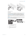
Sensing range setting WTS16
Detection of flat, glossy, contrast-rich, and uneven objects.
If the objects are detected from above, we recommend installing the sensor at an angle
in order to prevent total reflection by a reflective surface
1 When adjusting the sensing range, the light spot should be focused on an even,
uniform surface, e.g. a white sheet of paper.
6
COMMISSIONING
12
8022692.10DR | SICK
Subject to change without notice

1...3 sec.
Figure 11: WTS16 sensing range setting
2 Turn the potentiometer a fraction counterclockwise until the yellow LED indicator
no longer lights up. The sensing range is now located a fraction above the con‐
veyor belt.
Figure 12: WTS16 sensing range setting
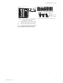
3 The conveyor belt should now be put into operation without any objects. If the yel‐
low LED indicator does not light up during the test run, the sensing range is set
correctly.
Figure 13: WTS16 sensing range setting
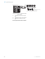
4 If the object is in the path of the beam and the yellow LED indicator lights up, the
sensing range is set correctly.
COMMISSIONING
6
8022692.10DR | SICK
Subject to change without notice
13

Figure 14: WTS16 sensing range setting
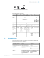
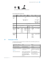
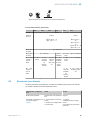
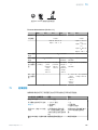
Process data structure (Version 1.1)
A00 A70 A71 A72 A73 A75
IO-Link V1.1
Process
data
2 bytes 4 bytes
Byte 0: bits 15... 8
Byte 1: bits 7... 0
Byte 0: bits 31...
24
Byte 1: bits 13...
16
Byte 2: bits 15...
8
Byte 3: bits 7... 0
Bit 0 / Data
type
Q
L1
/ Boolean
Bit 1 / Data
type
Q
L2
/ Boolean Qint.1 /
Boolean
Q
L2
/
Boolean
Qint.1 / Boolean
Bit... /
Descrip‐
tion / Data
type
2 ...15 /
[empty]
2 ...15 /
[time mea‐
surement
value] /
UInt 14
2 … 15 /
[counter
value] /
UInt 14
2 … 15 /
[length /
speed
measure‐
ment] /
SInt14
2 / Qint.
1 /
Boolean
2 … 7 / [empty]
Bit... /
Descrip‐
tion / Data
type
3 … 15 /
[time mea‐
surement
value] /
UInt13
8 … 31 / [carrier
load] / UInt 24
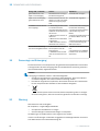
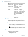
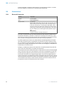
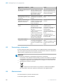
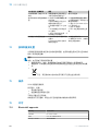
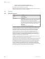
7 Troubleshooting
The Troubleshooting table indicates measures to be taken if the sensor stops working.
LED indicator/fault pattern Cause Measures
Green LED flashes IO-Link communication None
Switching outputs do not
behave in accordance with
table 2
1. IO-Link communication
2. Change of the configuration
3. Short-circuit
1. None
2. Adjustment of the configura‐
tion
3. Check electrical connections
WTS only: yellow LED flashes
quickly
When adjusting the sensing
range, the light spot is only
half on the object or on a very
high-contrast object
Sensing range setting accord‐
ing to Section “Sensing range
setting for WTS16”.
Yellow LED lights up, no object
in the path of the beam
The sensing range distance is
too large
Reduce the sensing range
7 TROUBLESHOOTING
14
8022692.10DR | SICK
Subject to change without notice

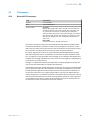
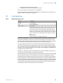
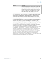
LED indicator/fault pattern Cause Measures
Object is in the path of the
beam, yellow LED does not
light up
Distance between the sensor
and the object is too long or
sensing range is set too short
Increase the sensing range
The sensor is not displayed in
SOPASair
1. Connection to another
hand-held exists.
2.The hand-held is outside of
the transmission range of the
sensor.
3. Bluetooth LE in the sensor
is deactivated.
4. Bluetooth LE in the hand-
held is deactivated.
5. MAC address filter acti‐
vated, hand-held not autho‐
rized.
1. No connection or deactiva‐
tion of the existing connection.
2. Thorough check of installa‐
tion situation (e.g. shielding by
metal).
3. Activation of Bluetooth LE
via SiLink2 master or IO-Link
4. Activation of Bluetooth LE
5. No or change to MAC
address filter.
No connection can be made
to the sensor
1. The Android or iOS version
does not comply with require‐
ments.
2. SOPASair version does not
contain the required driver.
1. Check the operating system.
2. Uninstall SOPASair, install
the most current app version.
8 Disassembly and disposal
The sensor must be disposed of according to the applicable country-specific regula‐
tions. Efforts should be made during the disposal process to recycle the constituent
materials (particularly precious metals).
NOTE
Disposal of batteries, electric and electronic devices
•
According to international directives, batteries, accumulators and electrical or
electronic devices must not be disposed of in general waste.
•
The owner is obliged by law to return this devices at the end of their life to the
respective public collection points.
•
This symbol on the product, its package or in this document, indicates
that a product is subject to these regulations.
9 Maintenance
SICK sensors are maintenance-free.
We recommend doing the following regularly:
•
Clean the external lens surfaces
•
Check the screw connections and plug-in connections
No modifications may be made to devices.
Subject to change without notice. Specified product properties and technical data are
not written guarantees.
DISASSEMBLY AND DISPOSAL 8
8022692.10DR | SICK
Subject to change without notice
15

10 Approvals
10.1 Bluetooth® approvals
Country Comments
Canada IC: 21147-W16
USA FCC ID: 2AHDR-W16
Europe + EFTA EU countries
Belgium (BE), Bulgaria (BG), Denmark (DK), Germany (DE), Estonia
(EE), Finland (FI), France (FR), Greece (GR), Ireland (IE), Italy (IT),
Latvia (LV), Lithuania (LT), Luxembourg (LU), Malta (MT), Nether‐
lands (NL), Austria (AT), Poland (PL), Portugal (PT), Romania (RO),
Sweden (SE), Slovakia (SK), Slovenia (SI), Spain (ES), Czech
Republic (CZ), Hungary (HU), United Kingdom (GB), Republic of
Cyprus (CY).
EFTA countries
Iceland, Liechtenstein, Norway, Switzerland
This device complies with Part 15 of the FCC Rules and with Industry Canada licence-
exempt RSS standard(s). Operation is subject to the following two conditions: (1) this
device may not cause harmful interference, and (2) this device must accept any inter‐
ference received, including interference that may cause undesired operation.
Le présent appareil est conforme aux CNR d'Industrie Canada applicables aux
appareils radio exempts de licence. L'exploitation est autorisée aux deux conditions
suivantes: (1) l'appareil ne doit pas produire de brouillage, et (2) l'utilisateur de
l'appareil doit accepter tout brouillage radioélectrique subi, même si le brouillage est
susceptible d'en compromettre le fonctionnement.
Changes or modifications made to this equipment not expressly approved by SICK AG
may void the FCC authorization to operate this equipment.
This equipment has been tested and found to comply with the limits for a Class A digital
device, pursuant to Part 15 of the FCC Rules. These limits are designed to provide rea‐
sonable protection against harmful interference when the equipment is operated in a
commercial environment. This equipment generates, uses, and can radiate radio fre‐
quency energy and, if not installed and used in accordance with the instruction manual,
may cause harmful interference to radio communications. Operation of this equipment
in a residential area is likely to cause harmful interference in which case the user will
be required to correct the interference at his own expense.
10
APPROVALS
16
8022692.10DR | SICK
Subject to change without notice

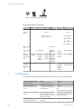
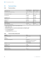
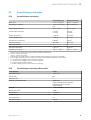
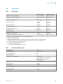
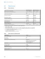
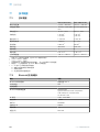
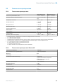
11 Technical data
11.1 Technical data
WTL16 Bluetooth® WTS16 Bluetooth®
Sensing range max. 10 mm ... 500 mm
1
10 mm ... 750 mm
1
Light spot diameter/distance 30 mm x 3 mm (200
mm)
Ø 8 mm (300 mm)
Supply voltage V
S
DC 10 ... 30 V DC 10 ... 30 V
Current consumption ≤ 30 mA
2
< 50 mA
3
≤ 30 mA
2
< 50 mA
3
Output current I
max.
≤ 100 mA ≤ 100 mA
Max. response time ≤ 500 µs
4
≤ 1,4 ms
4
Switching frequency 1000 Hz
5
350 Hz
5
Enclosure rating IP66, IP67 IP66, IP67
Protection class III III
Circuit protection A, B, C, D
6
A, B, C, D
6
Ambient operating temperature –40 °C ... +60 °C –40 °C ... +60 °C
1
Object with 90 % remission (based on standard white DIN 5033)
2
16 VDC to 30 VDC, without load
3
10 VDC to 16 VDC, without load
4
Signal transit time with resistive load in switching mode. Deviating values possible in COM2 mode.
5
With a light/dark ratio of 1:1 in switching mode. Deviating values possible in IO-Link mode.
6
A = U
V
-connections reverse polarity protected
B = inputs and output reverse-polarity protected
C = Interference suppression
D = outputs overcurrent and short-circuit protected
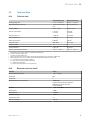
11.2 Bluetooth technical data®
Features Values
Bluetooth® sensing range 100 m on sight
Radio type BLE
Radio class 2
Bluetooth® module manufacturer BROADCOM
Cypress Semiconductor Corporation
198 Champion Court San Jose
CA 95134-1709
RF band 2,402 - 2,480 MHz
Output power 2 dBM
Declaration ID D033906
Qualified design ID 89630
Specification name 4.1
Member company SICK AG
TECHNICAL DATA 11
8022692.10DR | SICK
Subject to change without notice
17


Beschriebenes Produkt
WTL16, WTS16 - Bluetooth®
Hersteller
SICK AG
Erwin-Sick-Str. 1
79183 Waldkirch
Deutschland
Rechtliche Hinweise
Dieses Werk ist urheberrechtlich geschützt. Die dadurch begründeten Rechte bleiben
bei der Firma SICK AG. Die Vervielfältigung des Werks oder von Teilen dieses Werks ist
nur in den Grenzen der gesetzlichen Bestimmungen des Urheberrechtsgesetzes zuläs‐
sig. Jede Änderung, Kürzung oder Übersetzung des Werks ohne ausdrückliche schriftli‐
che Zustimmung der Firma SICK AG ist untersagt.
Die in diesem Dokument genannten Marken sind Eigentum ihrer jeweiligen Inhaber.
© SICK AG. Alle Rechte vorbehalten.
Originaldokument
Dieses Dokument ist ein Originaldokument der SICK AG.
8022692.10DR | SICK
Subject to change without notice
19
La pagina si sta caricando...
La pagina si sta caricando...
La pagina si sta caricando...
La pagina si sta caricando...
La pagina si sta caricando...
La pagina si sta caricando...
La pagina si sta caricando...
La pagina si sta caricando...
La pagina si sta caricando...
La pagina si sta caricando...
La pagina si sta caricando...
La pagina si sta caricando...
La pagina si sta caricando...
La pagina si sta caricando...
La pagina si sta caricando...
La pagina si sta caricando...
La pagina si sta caricando...
La pagina si sta caricando...
La pagina si sta caricando...
La pagina si sta caricando...
La pagina si sta caricando...
La pagina si sta caricando...
La pagina si sta caricando...
La pagina si sta caricando...
La pagina si sta caricando...
La pagina si sta caricando...
La pagina si sta caricando...
La pagina si sta caricando...
La pagina si sta caricando...
La pagina si sta caricando...
La pagina si sta caricando...
La pagina si sta caricando...
La pagina si sta caricando...
La pagina si sta caricando...
La pagina si sta caricando...
La pagina si sta caricando...
La pagina si sta caricando...
La pagina si sta caricando...
La pagina si sta caricando...
La pagina si sta caricando...
La pagina si sta caricando...
La pagina si sta caricando...
La pagina si sta caricando...
La pagina si sta caricando...
La pagina si sta caricando...
La pagina si sta caricando...
La pagina si sta caricando...
La pagina si sta caricando...
La pagina si sta caricando...
La pagina si sta caricando...
La pagina si sta caricando...
La pagina si sta caricando...
La pagina si sta caricando...
La pagina si sta caricando...
La pagina si sta caricando...
La pagina si sta caricando...
La pagina si sta caricando...
La pagina si sta caricando...
La pagina si sta caricando...
La pagina si sta caricando...
La pagina si sta caricando...
La pagina si sta caricando...
La pagina si sta caricando...
La pagina si sta caricando...
La pagina si sta caricando...
La pagina si sta caricando...
La pagina si sta caricando...
La pagina si sta caricando...
La pagina si sta caricando...
La pagina si sta caricando...
La pagina si sta caricando...
La pagina si sta caricando...
La pagina si sta caricando...
La pagina si sta caricando...
La pagina si sta caricando...
La pagina si sta caricando...
La pagina si sta caricando...
La pagina si sta caricando...
La pagina si sta caricando...
La pagina si sta caricando...
La pagina si sta caricando...
La pagina si sta caricando...
La pagina si sta caricando...
La pagina si sta caricando...
La pagina si sta caricando...
La pagina si sta caricando...
La pagina si sta caricando...
La pagina si sta caricando...
La pagina si sta caricando...
La pagina si sta caricando...
La pagina si sta caricando...
La pagina si sta caricando...
La pagina si sta caricando...
La pagina si sta caricando...
La pagina si sta caricando...
La pagina si sta caricando...
La pagina si sta caricando...
La pagina si sta caricando...
La pagina si sta caricando...
La pagina si sta caricando...
La pagina si sta caricando...
La pagina si sta caricando...
La pagina si sta caricando...
La pagina si sta caricando...
La pagina si sta caricando...
La pagina si sta caricando...
La pagina si sta caricando...
La pagina si sta caricando...
La pagina si sta caricando...
La pagina si sta caricando...
La pagina si sta caricando...
La pagina si sta caricando...
La pagina si sta caricando...
La pagina si sta caricando...
La pagina si sta caricando...
La pagina si sta caricando...
La pagina si sta caricando...
La pagina si sta caricando...
La pagina si sta caricando...
La pagina si sta caricando...
La pagina si sta caricando...
La pagina si sta caricando...
La pagina si sta caricando...
La pagina si sta caricando...
La pagina si sta caricando...
La pagina si sta caricando...
La pagina si sta caricando...
La pagina si sta caricando...
La pagina si sta caricando...
La pagina si sta caricando...
La pagina si sta caricando...
La pagina si sta caricando...
La pagina si sta caricando...
-
 1
1
-
 2
2
-
 3
3
-
 4
4
-
 5
5
-
 6
6
-
 7
7
-
 8
8
-
 9
9
-
 10
10
-
 11
11
-
 12
12
-
 13
13
-
 14
14
-
 15
15
-
 16
16
-
 17
17
-
 18
18
-
 19
19
-
 20
20
-
 21
21
-
 22
22
-
 23
23
-
 24
24
-
 25
25
-
 26
26
-
 27
27
-
 28
28
-
 29
29
-
 30
30
-
 31
31
-
 32
32
-
 33
33
-
 34
34
-
 35
35
-
 36
36
-
 37
37
-
 38
38
-
 39
39
-
 40
40
-
 41
41
-
 42
42
-
 43
43
-
 44
44
-
 45
45
-
 46
46
-
 47
47
-
 48
48
-
 49
49
-
 50
50
-
 51
51
-
 52
52
-
 53
53
-
 54
54
-
 55
55
-
 56
56
-
 57
57
-
 58
58
-
 59
59
-
 60
60
-
 61
61
-
 62
62
-
 63
63
-
 64
64
-
 65
65
-
 66
66
-
 67
67
-
 68
68
-
 69
69
-
 70
70
-
 71
71
-
 72
72
-
 73
73
-
 74
74
-
 75
75
-
 76
76
-
 77
77
-
 78
78
-
 79
79
-
 80
80
-
 81
81
-
 82
82
-
 83
83
-
 84
84
-
 85
85
-
 86
86
-
 87
87
-
 88
88
-
 89
89
-
 90
90
-
 91
91
-
 92
92
-
 93
93
-
 94
94
-
 95
95
-
 96
96
-
 97
97
-
 98
98
-
 99
99
-
 100
100
-
 101
101
-
 102
102
-
 103
103
-
 104
104
-
 105
105
-
 106
106
-
 107
107
-
 108
108
-
 109
109
-
 110
110
-
 111
111
-
 112
112
-
 113
113
-
 114
114
-
 115
115
-
 116
116
-
 117
117
-
 118
118
-
 119
119
-
 120
120
-
 121
121
-
 122
122
-
 123
123
-
 124
124
-
 125
125
-
 126
126
-
 127
127
-
 128
128
-
 129
129
-
 130
130
-
 131
131
-
 132
132
-
 133
133
-
 134
134
-
 135
135
-
 136
136
-
 137
137
-
 138
138
-
 139
139
-
 140
140
-
 141
141
-
 142
142
-
 143
143
-
 144
144
-
 145
145
-
 146
146
-
 147
147
-
 148
148
-
 149
149
-
 150
150
-
 151
151
-
 152
152
-
 153
153


SICK WTL16 Bluetooth Istruzioni per l'uso
- Tipo
- Istruzioni per l'uso
- Questo manuale è adatto anche per
in altre lingue
Documenti correlati
-
SICK WTL-S16 Istruzioni per l'uso
-
-
-
-
-
-
-
-
-