
1/7
Divisione della BETA UTENSILI SPA, Via Volta, 18 - 20845 SOVICO (MB) ITALY Tel. +39.039.20771-Fax + 39.039.2010742
SPECIFICA PRODOTTO
ISTRUZIONI PER L’USO E LA MANUTENZIONE
Informazioni tecniche
Condizioni d’uso previste e limiti operativi
Prescrizioni per gli operatori
Rischi residui
Modalità e frequenza delle ispezioni periodiche d’idoneità
COLLARI PER SOSTEGNO TUBAZIONI
SERIE PESANTE, ZINCATI
ARTICOLO 8381SP
La lingua originale della presente specifica è quella Italiana.
Sede produttiva Accessori per funi ROBUR
Zona Industriale – C.da S. Nicola
67039 SULMONA (L’AQUILA)
Tel. +39.0864.2504.1 – Fax +39.0864.253132
www.beta-tools.com – info@roburitaly.com
1) CARATTERISTICHE TECNICHE DELL’ACCESSORIO
R/SP/8381SP/05
Data 25/06/2020

2/7
Divisione della BETA UTENSILI SPA, Via Volta, 18 - 20845 SOVICO (MB) ITALY Tel. +39.039.20771-Fax + 39.039.2010742
MATERIALE:
COLLARE acciaio classe di resistenza 4.8 UNI EN 20898/1
DADO classe di resistenza 8 UNI 5588
RONDELLA UNI EN 7089 200HV
TRATTAMENTO SUPERFICIALE:
COLLARE zincatura elettrolitica A3E UNI EN ISO 4042
DADO zincatura elettrolitica A3E UNI EN ISO 4042
RONDELLA zincatura elettrolitica A3E UNI EN ISO 4042
Il collaudo viene eseguito in base a specifiche e regole interne in riferimento alla norma UNI EN ISO 9001.

3/7
Divisione della BETA UTENSILI SPA, Via Volta, 18 - 20845 SOVICO (MB) ITALY Tel. +39.039.20771-Fax + 39.039.2010742
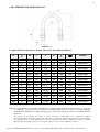
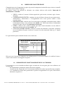
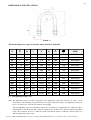
CARATTERISTICHE DIMENSIONALI:
TABELLA “A”
Le quote indicate sono espresse in mm, salvo dove diversamente indicato.
C = Coppia di serraggio dado (Nm)
NB = Le coppie indicate sono quelle consigliate per il serraggio degli elementi filettati, in modo da ostacolare
lo svitamento e non provocare la rottura dei gambi filettati. Nel caso in cui il collare comprima
direttamente la tubazione, la coppia di serraggio può dover essere ridotta per evitare la deformazione della
tubazione.
La coppia di serraggio del dado è stata calcolata considerando un coefficiente d'attrito
dell'accoppiamento dado-vite pari a 0.14, valevole per condizioni standard di fornitura. L'uso del collare
in condizioni diverse dallo standard di fornitura comporta un diverso coefficiente d'attrito, peraltro
difficilmente misurabile, da cui ne consegue un diverso valore della coppia di serraggio.
D
D
gas
M L S B
C
Nm
g
CODICE
22
1/2’’ M8
59 7,10
30
12,5
54 083810301
27
3/4’’ M8
63 7,10
30
12,5
58 083810302
34
1’’ M8
71 7,10
30
12,5
64 083810303
43
1’’1/4 M8
79 7,10
30
12,5
70 083810304
49
1’’ 1/2 M10
91 8,90
40
25
130 083810305
61
2’’ M10
103 8,90
40
25
145 083810306
77
2’’ 1/2 M10
119 8,90
40
25
168 083810307
89
3’’ M10
131 8,90
40
25
180 083810308
102
3’’ 1/2 M12 153 10,75
50
42
300 083810309
115
4’’ M12 167 10,75
50
42
325 083810310
168
6” M16 240 14.60 70
106
880 083810315
220
8” M16 282 14.60 60
106
930 083810320
274
10” M16 336 14.60 60
106
1110 083810374
274
10” M20 356 18.20 80
206
1895 083810375
324
12” M20 397 18.20 70
206
2100 083810386
408
16” M24 502 21.90 90
355
3800 083810508

4/7
Divisione della BETA UTENSILI SPA, Via Volta, 18 - 20845 SOVICO (MB) ITALY Tel. +39.039.20771-Fax + 39.039.2010742
Nel caso si operi una lubrificazione delle filettature, le coppie di serraggio indicate in tabella vanno
ridotte del 20%.
Definizioni:
• Ispezione: controllo visivo relativo allo stato dell’elemento per individuare evidenti danneggiamenti o
usure che possono alterarne l’utilizzo.
• Esame accurato: esame visivo effettuato da una persona competente e, se necessario, coadiuvato da
altri mezzi, quali i controlli non-distruttivi, al fine di individuare danneggiamenti o usure che possono
alterare l’utilizzo dell’articolo.
• Persona competente: persona designata, istruita correttamente, qualificata per conoscenza ed
esperienza pratica, che ha ricevuto le istruzioni necessarie per eseguire le prove e gli esami richiesti.
2) SPECIFICHE DI COLLAUDO
L’articolo è sottoposto a una serie di severi controlli a campione per accertarne la funzionalità prestazionale
e la rispondenza alle specifiche.
La numerosità del campione e i relativi piani di campionamento sono scelti in funzione della caratteristica
da verificare in accordo e per quanto previsto dalla norma UNI ISO 2859/1, e i risultati archiviati
nell’ufficio qualità dello stabilimento di Sulmona.
2.A Controllo dimensionale
Verifica che le dimensioni dell’articolo rientrino nelle tolleranze stabilite dai relativi
disegni di costruzione interni.
2.B Controllo visivo
Verifica la presenza di eventuali imperfezioni dovute a stampaggio, lavorazione meccanica
e rispondenza del rivestimento superficiale a disegni di fase interni.
3) AVVERTENZE GENERALI
Il manuale deve essere custodito da persona responsabile allo scopo preposta, in un luogo idoneo, affinché
esso risulti sempre disponibile per la consultazione nel miglior stato di conservazione. In caso di
smarrimento o deterioramento, la documentazione dovrà essere prontamente sostituita scaricandola dal sito
del costruttore: www.beta-tools.com.
Il costruttore si riserva la proprietà materiale ed intellettuale del presente manuale e ne vieta la modifica,
anche parziale, per fini commerciali.
Con riferimento a quanto riportato in queste istruzioni d’uso, la BETA UTENSILI SPA declina ogni
responsabilità in caso di:
• uso degli accessori contrario alle leggi nazionali sulla sicurezza e sull’antinfortunistica;
• errata scelta o predisposizione dell’apparecchio con il quale saranno connessi;
• mancata o errata osservanza delle istruzioni per l’uso;
• modifiche agli accessori;
• uso improprio e omessa manutenzione ordinaria;
• uso combinato ad accessori non conformi.

5/7
Divisione della BETA UTENSILI SPA, Via Volta, 18 - 20845 SOVICO (MB) ITALY Tel. +39.039.20771-Fax + 39.039.2010742
5) CRITERI DI SCELTA
I parametri che devono essere attentamente considerati nella scelta del collare sono:
5.A ELEMENTO DI ACCOPPIAMENTO
Assicurarsi che gli elementi di accoppiamento–collegamento siano adeguati alle caratteristiche del collare,
sia per quanto riguarda la geometria che la resistenza.
5.B TEMPERATURE D’IMPIEGO
La temperatura massima di utilizzo è +80 °C.
Per temperature al di sotto dello 0° utilizzare gli art. inox, quali ad esempio l’articolo Robur 8381SX.
5.C VITA E FREQUENZA DI UTILIZZO
L’accessorio lavora in perfetta efficienza fin quando restano invariate le sue caratteristiche geometriche e
fisiche.
Sostituire quindi il collare quando si notino riduzioni di sezione, deformazioni, corrosioni o instabilità di
accoppiamento.
6) CONDIZIONI NON AMMESSE
Non è consentito far lavorare i collari nei seguenti casi:
• nelle condizioni in cui si possono creare delle sollecitazioni di tipo dinamico o carichi
pulsanti;
• far lavorare i collari a temperature diverse da quelle consentite;
• montati su tubazioni di diametro maggiore o minore rispetto alla loro misura nominale.
7) CONTROLLI PRELIMINARI
Prima della messa in servizio e/o del montaggio gli accessori devono essere controllati da una persona
competente adeguatamente addestrata.
• Controllare l’integrità del collare e in particolare che non vi siano tagli, piegature,
incisioni, abrasioni, incrinature o cricche, filetti irregolari, corrosioni, bave taglienti,
usure provocate dall’utilizzo o difetti dovuti a cattivo stoccaggio.
• Rilevare e registrare le dimensioni con riferimento alla tabella “A”.
• Verificare la bontà dell’accoppiamento tra i filetti.
8) INSTALLAZIONE - ISTRUZIONI PER IL MONTAGGIO
Durante l’installazione dell’accessorio indossare i dispositivi di protezione adeguati:
guanti, scarpe antinfortunistiche, elmetto, etc.
I collari vengono usati preferibilmente in funzione di guida delle tubazioni e non sono adatti, se non
vengono presi adeguati accorgimenti, a sostenere carichi gravosi o a costituire punti fissi.
Il fissaggio avviene utilizzando dei dadi esagonali.

6/7
Divisione della BETA UTENSILI SPA, Via Volta, 18 - 20845 SOVICO (MB) ITALY Tel. +39.039.20771-Fax + 39.039.2010742
9) USO DELL’ACCESSORIO - PRESA E MANOVRA
Il collare è stato concepito per essere utilizzato in situazioni statiche. Controllare periodicamente la stabilità
del collare, lo stato di conservazione degli elementi e il loro accoppiamento, in riferimento alla tabella
“Interventi di manutenzione e controllo”.
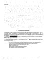
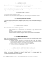
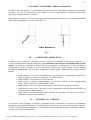
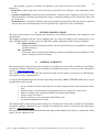
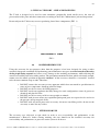
Non sottoporre il collare a sollecitazioni che generino componenti di forza laterali, ad esempio utilizzandolo
come punto di appoggio per carichi esterni (FIG. 1).
USO ERRATO
FIG. 1
10) CONTROINDICAZIONI D’USO
L’utilizzo dell’accessorio per scopi non previsti, il suo uso in condizioni estremamente pericolose e la
carenza di manutenzione possono comportare gravi situazioni di pericolo per l’incolumità delle persone
esposte e di danno per l’ambiente di lavoro, oltre che pregiudicare la funzionalità e la sicurezza effettiva
del prodotto. Le azioni di seguito citate, che, ovviamente, non possono coprire l’intero arco di potenziali
possibilità di “cattivo uso” dell’accessorio, costituiscono tuttavia quelle “ragionevolmente” più prevedibili.
Quindi:
• NON utilizzare l’accessorio collegandolo ad apparecchiature di dimensioni, temperatura,
punto d’aggancio e forma non idonei alle sue caratteristiche;
• NON utilizzare l’accessorio per il sollevamento;
• NON mettere in tensione apparecchiature che possono cambiare la loro configurazione
statica, il loro baricentro o lo stato chimico-fisico;
• NON utilizzare l’accessorio per il sollevamento o il trasporto di persone o animali;
• NON operare in aree dove è prescritto l’uso di componenti antideflagranti/antiscintilla o in
presenza di forti campi magnetici;
• NON saldare sull’accessorio particolari metallici, né intervenire con riporti di saldatura o
utilizzarlo come massa per saldatrici.
11) IDONEITÀ ALL’UTILIZZO
L’accessorio è stato sottoposto a collaudo a campione presso il costruttore per accertare la rispondenza
funzionale e prestazionale dello stesso. L’utilizzatore deve eseguire in ogni caso, prima di iniziare a operare,
la verifica della rispondenza funzionale e prestazionale dell’accessorio installato per confermare l’idoneità
all’impiego dell’intera installazione.

7/7
Divisione della BETA UTENSILI SPA, Via Volta, 18 - 20845 SOVICO (MB) ITALY Tel. +39.039.20771-Fax + 39.039.2010742
12) ISPEZIONE E MANUTENZIONE
Comprende una serie di operazioni eseguite da personale competente istruito allo scopo, relative a controlli
ed esami accurati durante l’impiego.
Di seguito l’elenco dei controlli da effettuare con cadenze indicate nella tabella “Interventi di
manutenzione e controllo”.
• VISIVO: verificare l’assenza di difetti superficiali, quali cricche, incisioni, tagli o fessure,
abrasioni.
• CONDIZIONI DEL FILETTO: esaminare lo stato del filetto, che non deve presentare usure,
deformazioni e ammaccature, e l’accoppiamento deve essere preciso, stabile e senza
eccessivo gioco.
• DEFORMAZIONE: verificare che l’accessorio non sia deformato, misurando con un calibro
le dimensioni critiche, come indicato nella tabella “A”. NON sono tollerate deformazioni
rispetto alle quote rilevate alla prima messa in servizio.
• USURA: verificare che i punti di contatto non siano usurati misurando con un calibro le
dimensioni critiche indicate nella tabella “A”.
• STATO DI CONSERVAZIONE: verificare l’assenza di ossidazione e corrosione, soprattutto
in caso di utilizzo all’aperto; verificare l’assenza di cricche con metodi idonei (p. es. liquidi
penetranti).
Le registrazioni di questi controlli devono essere conservate.
Nel caso in cui l’articolo sia sottoposto a un utilizzo gravoso, è necessario effettuare le verifiche di usura e
stato di conservazione con maggiore frequenza.
13) DEMOLIZIONE E ROTTAMAZIONE DELL’ACCESSORIO
L’accessorio deve essere demolito mediante taglio, in modo tale che non possa più essere utilizzato, nel
caso presenti:
- una deformazione permanente rispetto alla misura originale;
- eventuali cricche, distorsioni e/o se si riscontrano riduzioni di sezione rispetto alla misura originale;
- se le condizioni del filetto non garantiscono il perfetto accoppiamento tra le parti, filetti usurati,
deformati, irregolari ecc.
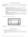
A ogni utilizzo Mese Anno
Controllo visivo gener.
x
Condizioni del filetto
x
Deformazione
x
Usura
x
Stato di conservazione
x
Tabella interventi di manutenzione e controllo
Tipo di controllo

1/7
Division of BETA UTENSILI SPA, Via Volta, 18 - 20845 SOVICO (MB) ITALY Tel. +39.(0)39.20771-Fax + 39.(0)39.2010742
PRODUCT SPECIFICATIONS
OPERATING AND MAINTENANCE INSTRUCTIONS
Technical Specifications
Operating Conditions and Limits
Operator’s Instructions
Residual Risks
How and how often periodical fitness inspections should be conducted
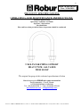
U BOLTS FOR PIPING SUPPORT
HEAVY TYPE, GALVAZED
ITEM 8381SP
The original language of this technical specification is Italian
Manufacturing site ROBUR wire rope accessories
Zona Industriale – C.da S. Nicola
I-67039 SULMONA (L’AQUILA)
Tel. +39.(0)864.2504.1 – Fax +39.(0)864.253132
www.beta-tools.com – info@roburitaly.com
R/SP/8381SP/05
Date 25/06/2020

2/7
Division of BETA UTENSILI SPA, Via Volta, 18 - 20845 SOVICO (MB) ITALY Tel. +39.(0)39.20771-Fax + 39.(0)39.2010742
1) TECHNICAL SPECIFICATIONS OF ACCESSORY
MATERIAL:
U-BOLT steel class 4.8 UNI EN 20898/1
NUT class 8 UNI 5588
WASHER UNI EN 7089 200HV
SURFACE TREATMENT:
U-BOLT electrogalvanized A3E UNI EN ISO 4042
NUT electrogalvanized A3E UNI EN ISO 4042
WASHER electrogalvanized A3E UNI EN ISO 4042
The test is performed on the basis of in-house specifications and rules in accordance with UNI EN ISO
9001.

3/7
Division of BETA UTENSILI SPA, Via Volta, 18 - 20845 SOVICO (MB) ITALY Tel. +39.(0)39.20771-Fax + 39.(0)39.2010742
DIMENSIONAL SPECIFICATIONS:
TABLE “A”
All measurements are expressed in mm, unless otherwise indicated.
C = Nut tightening torque (Nm)
NB = The tightening torques are those suggested for the tightening of threaded elements, in order to avoid
unscrewing or the breaking of the pins. If the U-bolt presses directly the pipe, the tightening torque may
have to be reduced to avoid the deformation of the piping.
The nut tightening torque was calculated on the basis of a nut/screw coupling friction coefficient of 0.14,
which applies to standard terms and conditions. Using the U-bolt under any conditions other than standard
terms and conditions involves a different, hardly measurable friction coefficient, which results in a
different tightening torque value.
D
D
gas
M L S B
C
Nm
g
CODE
22
1/2’’ M8
59 7,10
30
12,5
54 083810301
27
3/4’’ M8
63 7,10
30
12,5
58 083810302
34
1’’ M8
71 7,10
30
12,5
64 083810303
43
1’’1/4 M8
79 7,10
30
12,5
70 083810304
49
1’’ 1/2 M10
91 8,90
40
25
130 083810305
61
2’’ M10
103 8,90
40
25
145 083810306
77
2’’ 1/2 M10
119 8,90
40
25
168 083810307
89
3’’ M10
131 8,90
40
25
180 083810308
102
3’’ 1/2 M12 153 10,75
50
42
300 083810309
115
4’’ M12 167 10,75
50
42
325 083810310
168
6” M16 240 14.60 70
106
880 083810315
220
8” M16 282 14.60 60
106
930 083810320
274
10” M16 336 14.60 60
106
1110 083810374
274
10” M20 356 18.20 80
206
1895 083810375
324
12” M20 397 18.20 70
206
2100 083810386
408
16” M24 502 21.90 90
355
3800 083810508

4/7
Division of BETA UTENSILI SPA, Via Volta, 18 - 20845 SOVICO (MB) ITALY Tel. +39.(0)39.20771-Fax + 39.(0)39.2010742
When making a greasing of the thread, the tightening couples in the table must be reduced by 20%.
Definitions:
• Inspection: visual testing of the state of the item, to check for clear damage or wear which may affect
its use.
• Accurate examination: visual inspection performed by a trained person, supported, if need be, by any
other instruments, including non-destructive testing, to check for damage or wear which may affect the
use of the item.
• Trained person: a designated, suitably trained person who has proper know-how and practical expertise
and has been given the instructions needed to perform any required tests and examinations.
2) TESTING SPECIFICATIONS
The item is subjected to several stringent spot checks for serviceability, performance and compliance with
specifications.
The number of samples and the related sampling plans are chosen according to the characteristic to test
under UNI ISO 2859/1, and the results are filed in the quality department of the factory in Sulmona.
2.A Dimensional test
Making sure that the dimensions of the item meet such tolerances as established in in-house
working drawings.
2.B Visual test
Testing for defects resulting from forming, mechanical working and correspondence of the
surface coating to in-house drawings.
3) GENERAL WARNINGS
The manual must be kept by the person in charge in a suitable place and readily available for consultation,
in optimal conditions. Should it be lost or damaged, the manual can easily be retrieved on the constructor's
web site: www.beta-tools.com
The constructor detains all material and intellectual rights on the manual, and restricts its modification,
albeit partial, for any commercial use.
As regards the information provided in these operating instructions, BETA UTENSILI SPA will accept no
responsibility in the event of:
• any use of the accessories other than the uses under national safety and accident prevention
laws;
• mistaken choice or arrangement of the apparatus they are going to be connected to;
• failure to comply with, or properly follow, the operating instructions;
• changes to the accessories;
• misuse or failure to carry out routine maintenance jobs;
• use with noncompliant accessories.
The manual must be kept by the person in charge in a suitable place and readily available for consultation,
in optimal conditions. should it be lost or damaged, the manual can easily be retrieved on the constructor's
web site: www.roburitaly.com
The constructor detains all material and intellectual rights on the manual, and restricts its duplication, albeit
partial, for any commercial use.

5/7
Division of BETA UTENSILI SPA, Via Volta, 18 - 20845 SOVICO (MB) ITALY Tel. +39.(0)39.20771-Fax + 39.(0)39.2010742
5) SELECTION CRITERIA
The following parameters should be carefully considered in choosing the U bolt:
5.A CONNECTING PART
Make sure that the connecting parts suit the characteristics of the U bolt, in terms of both the structure and
strength.
5.B OPERATING TEMPERATURES
The maximum operating temperature is +80 °C.
For applications under 0 °C please use inox items, i. e. item 8381SX.
5.C LIFE AND FREQUENCY OF USE
The accessory is perfectly serviceable as long as its geometric and physical characteristics remain
unchanged.
Therefore, replace the U bolt whenever the sections become smaller, or deformations, corrosions or
connecting instability are shown.
6) NONPERMISSIBLE CONDITIONS
The U bolts should not be operated under the following circumstances:
• when dynamic stresses or swinging loads may result;
• when they are operated under any temperatures other than the permissible temperatures;
• when they are mounted to pipes bigger or smaller than the nominal size.
7) PRELIMINARY TESTS
Before the accessories are operated and/or assembled, they should be tested by a suitably trained person.
• Check the state of the wire rope clips; in particular make sure that they are free from
cuts, bends, indentations, abrasions, cracks, irregular threads, corrosions, sharp burrs,
wear or defects resulting from improper storage.
• Measure and record the dimensions according to Table “A”.
• Make sure that the threads fit.
8) INSTALLATION – ASSEMBLY INSTRUCTIONS
During the installation of the accessory please use adequate Personal Protective Equipment: gloves, safety
shoes, helmet, etc.
U-bolts are generally used for piping guide purposes and are not suitable to support heavy loads or to
constitute fixed points, if adequate precautions are not taken.
Fixing is carried out using the hex nuts.

6/7
Division of BETA UTENSILI SPA, Via Volta, 18 - 20845 SOVICO (MB) ITALY Tel. +39.(0)39.20771-Fax + 39.(0)39.2010742
9) USING ACCESSORY – GRIP AND HANDLING
The U bolt is designed to be used in static situations; periodically check tensile stress, the state of
preservation of the parts and their connection, according to the Table “Maintenance jobs and inspections”.
Do not subject the U bolt to any stresses producing lateral force components (FIG. 1).
INCORRECT USE
FIG. 1
10) NONPERMISSIBLE USE
Using the accessory for any purposes other than the purposes it has been designed for, using it under
extremely dangerous conditions and performing poor maintenance may pose a severe hazard to the safety
of the people being exposed and cause severe damage to the working environment, while affecting the
actual serviceability and safety of the product. The precautions mentioned below, which, obviously enough,
cannot cover the whole spectrum of potential “misuses” of the accessory, should be “reasonably” deemed
to be the most common steps to take. Therefore:
• DO NOT connect the accessory to any apparatus which does not match its specifications in
terms of size, temperature, hook-up point and shape;
• DO NOT use the accessory for lifting purposes;
• DO NOT stretch any apparatus that may change its static configuration, centre of gravity or
chemical and physical state;
• DO NOT use the accessory to lift or carry people or animals;
• DO NOT work in areas where any explosion/spark-proof parts are expected to be used or in
the presence of big magnetic fields;
• DO NOT weld any metal parts to the accessory; do not use any filling welds; do not use the
accessory as mass for any welder.
11) FITNESS FOR USE
The accessory was subjected to spot check in order to test serviceability and performance at the
manufacturer’s. However, before starting working, the user should test the installed accessory for
serviceability and performance, to prove the entire system is fit for use.

7/7
Division of BETA UTENSILI SPA, Via Volta, 18 - 20845 SOVICO (MB) ITALY Tel. +39.(0)39.20771-Fax + 39.(0)39.2010742
12) INSPECTION AND MAINTENANCE
Inspections and maintenance jobs should be carried out by trained personnel, who should perform accurate
tests during operation.
Below is a list of tests to perform at such intervals as stated in the table “Maintenance jobs and
inspections”.
• VISUAL TEST: making sure that the accessory is free from surface defects, including cracks,
indentations, cuts, fissures and abrasions.
• THREAD TEST: making sure that the thread is free from wear, deformation and dents, that
its fit is accurate and stable, and that there is not too much clearance.
• DEFORMATION TEST: making sure that the accessory has not got deformed, using a gauge
to measure such critical dimensions as shown in Table “A”. NO DEFORMATIONS will be
tolerated compared to the measurements made when the accessory was first put into
operation.
• WEAR TEST: making sure that the points of contact are not worn, using a gauge to measure
such critical dimensions as shown in Table “A”.
• PRESERVATION TEST: making sure that the accessory is free from oxidation and
corrosion, especially in case of outdoor use; using suitable methods (e.g. liquid penetrants) to
make sure that it is free from cracks.
The results of the above-mentioned tests should be stored.
If the item has been used for heavy-duty jobs, both wear and the state of preservation should be tested for
more frequently.
13) SCRAPPING ACCESSORY
The accessory should be scrapped by cutting, so that it can no longer be used, if:
- it is permanently worn compared to the original size;
- any cracks or distortions are shown, and/or the sections have become small compared to the original
size;
- the state of the thread is such that the parts do not fit perfectly, any threads are worn, deformed,
irregular etc.
Whenever used
Month Year
General visual inspection
x
Thread state
x
Deformation
x
Wear
x
State of preservation
x
Maintenance jobs and inspections
Type of inspection
-
 1
1
-
 2
2
-
 3
3
-
 4
4
-
 5
5
-
 6
6
-
 7
7
-
 8
8
-
 9
9
-
 10
10
-
 11
11
-
 12
12
-
 13
13
-
 14
14


in altre lingue
- English: Beta 8381SP Operating instructions
Documenti correlati
-
Beta 8381SX Istruzioni per l'uso
-
-
-
-
-
-
-
-
-