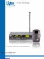
Listen Technologies Satellite Radio Manuale utente
- Categoria
- Attrezzatura musicale
- Tipo
- Manuale utente


Assistive Listening • Language Interpretation • Soundeld • Tour Group • Conferencing
Dear Valued Customer,
Thank you for choosing Listen! All of us at Listen are dedicated to providing
you with the highest quality products available. We take great pride in their
outstanding performance because we care that you are completely
satised. That’s why we independently certify them to the highest quality
standards and back them with a limited lifetime guarantee. We stand ready
to answer any questions you might have during installation or in the operation
of our products. Should you experience any problems whatsoever with your
Listen products, we are ready to help you in any way we can with prompt,
efcient customer care. Because at Listen, it’s all about you! And should you
have any comments on how we might improve our products or our
service, we’re here to listen.
Here’s how to reach us:
+1.801.233.8992
+1.800.330.0891 North America
+1.801.233.8995 fax
www.listentech.com
Thank you and enjoy your listening experience!
Best regards,
Russell Gentner and the Listen Team
• In the few instances where repairs were needed, 99% of all clients indicated that they were happy with
repair turn-around-times and 85% of the time, clients were without their product for less than 10 days!
• Overall client satisfaction of working with Listen was rated 4.8 out of 5.
• “ Please continue with your excellent attitude toward customer satisfaction. You guys are great!”
• “I’ve never had such good service from any company. Keep up the good work!”
• “You stand behind your product wonderfully.”


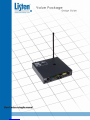
Design Guide LT-803-072 LR-200-072 Supplementary
Value Package Table of Contents
Design Guide
FM Technology Overview 5
System Overview 6
Key Concepts in Value Package Setup 7
Alternative Options for Value Package Setup 11
Notes 13
LT-803-072 Stationary FM Transmitter
Specications 20
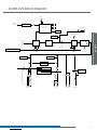
Block Diagram 21
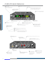
Quick Reference 22
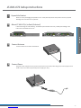
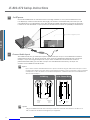
Setup Instructions 23
Operating Instructions 25
Accessories 29
Notes 30
LR-200-072 FM Receiver
Specications 36
Block Diagram 37
Quick Reference 38
Setup Instructions 39
Accessories 42
Notes 43
Supplementary Information
Battery Charging Information 50
Frequency Chart 51
Troubleshooting 52
Frequently Asked Questions 54
Compliance, Warranty and Contact Information 55
Notes 57


3
Design Guide
Value Package Design Guide Table of Contents
FM Technology Overview 5
System Overview 6
Key Concepts in Value Package Setup 7
Alternative Options for Value Package Setup 11
Notes 13
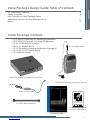
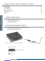
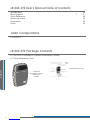
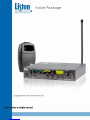
Value Package Contents
• (1) LT-803-072 Stationary 3-Channel FM Transmitter
• (4) LR-200-072 Standard 3-Channel FM Receiver
• (1) LA-123 90° Helical Antenna
• (4) LA-161 Single Ear Bud
• (1) LA-304 Assistive Listening Notication Signage Kit
• (1) LA-207 12 VDC Power Supply
• (1) Installation Guide
LT-803-072 Stationary 3-Channel FM Transmitter
12 VDC Power Supply
LA-123 90° Helical Antenna
LT-803
72
72
STANDARD RECEIVER
72
Alkaline
Battery Select
Channel Select
NiMH
Alkaline
Battery Select
Channel Select
NiMH
LA-161 Single Ear Bud
LR-200-072 Standard 3-Channel FM Receiver
This facility is equipped with a
hearing assistance system.
Please ask for a receiver.
Installation Guide
LA-304 Assitive Listening
Notication Signage Kit


5
Design Guide
72
STANDARD RECEIVER
LT-803
Audio Source
FM Receiver
FM Transmitter
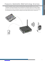
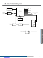
Frequency Modulation (FM) Technology Overview
Frequency modulation or (FM) is a means of transmitting audio using electromagnetic waves. This same
technology is used by local FM radio stations to broadcast music. FM signals can travel through most barriers
– walls, oors, and ceilings. The distance a signal travels has many different variables such as Radio Frequency
(RF) output power, the type and placement of the antenna, and the broadcasted frequency. Unlike infrared,
FM transmission are not secure. This enables a receiver to travel further distances from the source. This section of
the manual will help you design a system that will get the best range and least amount of interference.
Audio Mixer

6
Design Guide
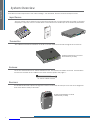
System Overview
There are four main components to the Value Package – the transmitter, antenna, receiver and input source.
The input source can be audio from a sound board, microphone or a personal audio source like a CD player,
MP3 player, computer, DVD, etc. Audio will be connected into the audio inputs of the Stationary Transmitter.
Input Source
The LT-803-072 transmitter modulates the audio on an FM carrier and transmits the signal via an antenna.
Transmitter
LT-803-072 Stationary 3-Channel
FM Transmitter (72 MHz)
The LP-3CV-072 includes the LA-123 90° Helical Antenna. This antenna has a BNC connector and should be
mounted on the back of the LT-803-072. For further antenna options see page 11.
Antenna
The LR-200-072 receiver captures the signal sent from the transmitter and outputs it into the LA-161 Single ear
bud. Listen offers a variety of receivers.
Receivers
LR-200-072 Standard 3-Channel
FM Receiver (72 MHz)
72
72
72
STANDARD RECEIVER
Alkaline
Battery Select
Channel Select
NiMH
Alkaline
Battery Select
Channel Select
NiMH
LA-123 90° Helical Antenna
LT-803

7
Design Guide
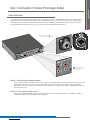
Input 1 offers a choice of balanced XLR or ¼ in. phono connector. Plug an audio source into Input 1: move the
input select switch to the type of input source being used. Select “Line” for Line Inputs, “Mic” for dynamic
microphones or “Mic + PH Power” for condenser microphones. A balanced feed from a soundboard can also
be used with Input 1.
Key Concepts in Value Package Setup
Input Selection
Input 1: Connecting the audio source
The LT-803-072 has two audio input options: Input 1 and Input 2. Input 1 is a balanced connection using either an
XLR or ¼ in. phono connector, and input 2 is two unbalanced phono connectors. Use Input 1 if you are using a
microphone or if you have a balanced connection such as a professional audio mixer (you can also use Input 1
for unbalanced connections). Use Input 2 to connect to an unbalanced audio source.
Balanced XLR or
1/4 in. phono connector
Unbalanced right
and left phono
connectors
Plug your unbalanced audio source into Input 2 and select the audio level switch for -10 dBu or +10 dBu to
match the audio level coming from your equipment.
Input 2: Connect the audio source

8
Design Guide
LT-803
LT-803
Key Concepts in Value Package Setup
The LT-803-072 can accommodate multiple inputs simultaneously with the use of the input level
potentiometer. When multiple inputs are present, both input level lights will be activated.
Using Multiple inputs
Mix Level
The mix level acts as the “master transmit” control. It will increase the transmit gain on the “mix” of the two
levels (if two levels are in use).
Input Level Knob
Mix Level Adjustment

9
Design Guide
LT-803
LT-803
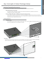
Test Tone
Use the test tone to transmit a 400 Hz tone. This tone will allow the end user to know if the system is transmitting
properly. All receivers should be able to hear this tone if tuned to the proper channel.
Selecting Transmitting Frequencies
Use this section of the guide to choose the channel settings for the transmitter and receivers.
Find transmission channel(s)
The goal is to nd a transmission channel(s) that is free from interference. Interference comes from
transmitters and other outside FM signals.
Listen’s LT-803-072 oers 3 dierent channels to choose from
With 3 different channels to choose from, the chance of nding an interference free channel is increased.
The best way to check for interference is to turn the LR-200-072 on and listen to each channel. Transmit on the
channel that has the least amount of noise.
Testing System
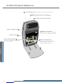
Monitor Jack
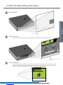
The headphone jack is used to monitor the mix of input 1 & 2. You can adjust the monitor level with the volume
knob. The headphone jack is a standard 3.5 mm jack.
Key Concepts in Value Package Setup
Test Tone Button
3
Headphone
Monitoring Jack

10
Design Guide
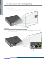
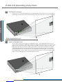
Key Concepts in Value Package Setup
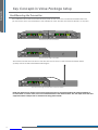
Antenna placement (rear)
Rear mounted antenna
Rear mounting the LA-123 90° Helical Antenna (72 MHz) will allow the transmitter to be moved if necessary.
For proper and dependable operation, Listen receivers need to receive a strong and consistent signal from the
originating transmitter. The following strategies should be used to maximize this signal:
Maximizing Transmission Range
Transmitting antenna
When designing and installing your system, keep in mind that the location of both the transmitting and
receiving antennas is critical to maximize broadcast range. Minimize the distance and remove any obstructions
between the transmitting and receiving antennas. Keep transmitting and receiving antennas (receiver earphone
cord) away from metal or conductive objects.
RF Power switch
Position the RF Power switch on the back of the LT-803-072 to full RF Power, unless lower power is necessary.
Low, med or high RF power

11
Design Guide
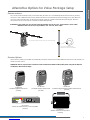
Remote antenna
The LA-122 Universal Antenna Kit (72 and 216 MHz) and the LA-116 Coaxial Dipole Remote Antenna (72 MHz)
connect to the LT-803-072 and can be placed away from the transmitter for better range. They also allow the
unit to be rack mounted with the antenna remotely using the LA-326 Universal Rack Mounting Kit. Both the
LA-122 and LA-116 come with 25’ of black coaxial cable (RG-58).
ATTENTION: Long cable runs can result in signal degradation due to the “loss” characteristics of the cable.
Minimize cable runs as much as possible or use “low loss” RG-8 cable.
LA-122 Universal Antenna Kit (72 and 216 MHz)
Alternative Options for Value Package Setup
LR-300-072
Portable Digital FM Receiver
(72 MHz)
LR-400-072
Portable Display FM Receiver
(72 MHz)
LR-500-072
Portable Programmable Display FM Receiver
(72 MHz)
LR-100-072
Stationary FM Receiver/ Power Amplier
(72 MHz)
Headphone
Speaker
Seek
Channel
RF Power
Up
Down
Squelch
Mute
Power
LR-100
Output Level
Antenna
Power
Output
Aux
Battery Control
RX Only
RX +
AUX
RX or
AUX
Line
Mic
Speaker
12VDC
Ground
Up
Down
Mute
Common
+ +
-
Audio Output Auxiliary Input
Power
Antenna Battery
SQ
Seek
Channel
Charge
OOn
Ext Int
On O
ALK NiMH
15VAC
or
12VDC
EQ
Low Mid High
In
Auxiliary
Out
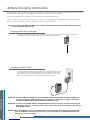
Battery Compartment
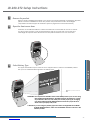
Instructions:
1. Install batteries with correct polarity as
observed on the battery holder.
2. Place BATTERY switch in “ALK” for
ALKALINE batteries and “HiMH” for NiMH
rechargeable batteries.
WARNING!
Do not attempt to charge
batteries that are not RECHARGEABLE.
Place battery switch in ALK position to
prevent batteries from being charged.
DAMAGE TO THE EQUIPMENT AND
SERIOUS INJURY COULD
OCCUR IF YOU ATTEMPT TO
CHARGE NON-RECHARGEABLE
BATTERIES!
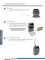
External Antenna
To use the external
antenna, select “EXT”
on the Antenna switch
CAN: 4011104425A G
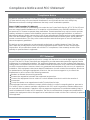
This device complies with part 15 of the FCC rules.
Operation is subject to the following two
conditions: (1) This device may not cause harmful
interference and (2) this device must accept any
interference received, including interference that
may cause undesired operation. This Class B digital
apparatus meets all requirements of the Canadian
Interference-Causing Equipment Regulations.
Listen Support: 1.800.330.0891.
+1.801.233.8992, www.ListenTech.com
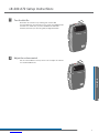
LR-600-072
Wireless FM Receiver/Speaker
(72 MHz)
Receiver Options
Listen offers a variety of portable and stationary receivers. Each receiver offers different features to help further cus-
tomize your FM system.
ATTENTION: The SQ “Super Quiet” function must be turned OFF for better audio quality when using the LT-803-072
contained in this Value Package.
LA-116 Coaxial Dipole
Remote Antenna (72 MHz)

12
Design Guide
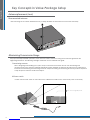
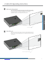
Key Concepts in Value Package Setup
The antenna can also be in the front of the rack with the use of the LA-125 Antenna Kit for Rack Mount
(72 MHz) and the LA-326 Universal Rack Mounting Kit.
Rack Mounting the Transmitter
The LT-803-072 can be rack mounted if necessary. With the use of the Listen LA-326 Universal Rack Mount Kit,
you can mount one or two transmitters to the standard 19” rack. The rack mounted unit will take 1 ru of space.
Rack Mount with dual units installed.
NOTE: The antenna may need to be remote mounted using the LA-122 Remote Antenna Kit if the transmitter(s) is
rack mounted. If a rack is metal, it is not recommended to have the antenna inside. Also, the depth of the rack and
equipment inside could prevent an antenna from being placed inside.
Rack Mount with single unit installed.
LT-803 FM Transmitter LT-803 FM Transmitter
LT-803 FM Transmitter
LT-803 FM Transmitter LT-803 FM Transmitter
LT-803 FM Transmitter
LT-803 FM Transmitter
LT-803 FM Transmitter
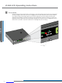
Rack Mount with single unit and external antenna installed.


La pagina si sta caricando...
La pagina si sta caricando...
La pagina si sta caricando...
La pagina si sta caricando...
La pagina si sta caricando...
La pagina si sta caricando...
La pagina si sta caricando...
La pagina si sta caricando...
La pagina si sta caricando...
La pagina si sta caricando...
La pagina si sta caricando...
La pagina si sta caricando...
La pagina si sta caricando...
La pagina si sta caricando...
La pagina si sta caricando...
La pagina si sta caricando...
La pagina si sta caricando...
La pagina si sta caricando...
La pagina si sta caricando...
La pagina si sta caricando...
La pagina si sta caricando...
La pagina si sta caricando...
La pagina si sta caricando...
La pagina si sta caricando...
La pagina si sta caricando...
La pagina si sta caricando...
La pagina si sta caricando...
La pagina si sta caricando...
La pagina si sta caricando...
La pagina si sta caricando...
La pagina si sta caricando...
La pagina si sta caricando...
La pagina si sta caricando...
La pagina si sta caricando...
La pagina si sta caricando...
La pagina si sta caricando...
La pagina si sta caricando...
La pagina si sta caricando...
La pagina si sta caricando...
La pagina si sta caricando...
La pagina si sta caricando...
La pagina si sta caricando...
La pagina si sta caricando...
La pagina si sta caricando...
La pagina si sta caricando...
-
 1
1
-
 2
2
-
 3
3
-
 4
4
-
 5
5
-
 6
6
-
 7
7
-
 8
8
-
 9
9
-
 10
10
-
 11
11
-
 12
12
-
 13
13
-
 14
14
-
 15
15
-
 16
16
-
 17
17
-
 18
18
-
 19
19
-
 20
20
-
 21
21
-
 22
22
-
 23
23
-
 24
24
-
 25
25
-
 26
26
-
 27
27
-
 28
28
-
 29
29
-
 30
30
-
 31
31
-
 32
32
-
 33
33
-
 34
34
-
 35
35
-
 36
36
-
 37
37
-
 38
38
-
 39
39
-
 40
40
-
 41
41
-
 42
42
-
 43
43
-
 44
44
-
 45
45
-
 46
46
-
 47
47
-
 48
48
-
 49
49
-
 50
50
-
 51
51
-
 52
52
-
 53
53
-
 54
54
-
 55
55
-
 56
56
-
 57
57
-
 58
58
-
 59
59
-
 60
60
-
 61
61
-
 62
62
-
 63
63
-
 64
64
-
 65
65


Listen Technologies Satellite Radio Manuale utente
- Categoria
- Attrezzatura musicale
- Tipo
- Manuale utente
in altre lingue
Altri documenti
-
WisyCom MRK 950 EX Manuale utente
-
-
Yamaha EMX5014C Manuale utente
-
-
-
LD Systems U306 R2 Manuale del proprietario
-
Yamaha 4FX Manuale utente
-
Samsung LE46N73BD Manuale utente
-
Yamaha MG 6FX Manuale utente
-