Rockford Fosgate RFQ5000 Setup Instructions
- Categoria
- Amplificatori audio per auto
- Tipo
- Setup Instructions


1
INTRODUCTIOn
What is the RFQ5000?
The RFQ5000 is a surround sound processor that is designed to enhance the listening experience
for both music and movie soundtracks. The RFQ5000 is the brainchild of Jim Fosgate. Jim intro-
duced the first Fosgate car amplifier in 1973! Since 1980 Jim has been perfecting the art of sur-
round sound, both in the home and the car. The RFQ5000 is the culmination of Jim’s efforts com-
bined with Rockford Fosgate engineering. The result is a processor that delivers pinpoint, precise
imaging with music, and superb sound effects typical of movies. Because the RFQ5000 has only
analog inputs and works totally in the analog domain, it works with ANY source, even existing sys-
tems. The RFQ5000 will properly decode Dolby Digital™, AC-3™, 5.1, or DTS™ encoded record-
ings. It also works wonders for traditional two channel recordings. If you are an audio fanatic or a
competitor, the RFQ5000 will amaze you with its ability to deliver a lifelike stereo image. The
RFQ5000 is truly a revolution in surround sound technology. Hear all your music again…for the
first time!
The RFQ5000 is not…
The RFQ5000 is not a digital signal processing echo box! There is no digital processing done
inside it, and it will not mimic the acoustic properties of your local football stadium. The
RFQ5000 simply produces what the artist intended. Whatever the source, movie soundtracks,
audiophile compact discs, or 10 year old cassette tapes, the RFQ5000 will reproduce them like no
other processor. Movies come alive with sound effects. Music is produced with amazing accuracy,
pinpoint imaging, and a sense of air and space that opens up the typical confined listening
environment of the vehicle.

2
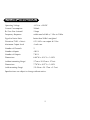
specifications
Operating Voltage +10V to +16VDC
Current Consumption 500mA
B+ Fuse Size (internal) 2 Amp
Frequency Response within one half db +/- 10hz to 50khz
Signal-to-Noise Ratio better than 90db A weighted
Distortion (THD + Noise) 0.5% @ 2v rms output @ 1 khz
Maximum Output Level 4 volts rms
Number of Channels 5
Number of Inputs 4 RCA
Number of Outputs 7 RCA
Dimensions 6.80”W x 8.14”L x 1.08”H
(without mounting flange) (17cm x 20.35cm x 2.7cm)
Dimensions 7.78”W x 8.07”L x 1.08”H
(with mounting flange) (19.45cm x 20.17cm x 2.7cm)
Specifications are subject to change without notice.

3
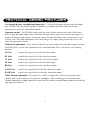
technical design features
Five channel discrete surround sound processing – Utilizing high speed voltage controlled ampli-
fiers, the RFQ5000 accurately decodes all modes of surround sound and sends the discrete
information to each of 5 individual channels.
Panorama control – The RFQ5000 works with any two channel analog source, but if the source
unit has dual pre-amp outputs (like all Rockford Fosgate source units) you can take advantage of a
feature called panorama control. Panorama control converts the fader in the source unit to a con-
trol that varies the width and depth of the stereo image. By simply fading from front to rear, you
adjust the panorama control.
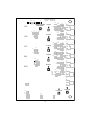
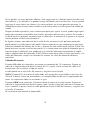
Output level adjustments – these internal controls are used to adjust the individual output channels
of the RFQ5000, so that each channel has the same amplitude (SPL) at the drivers seat listening
position.
LF Gain: controls the signal level of the left front output
RF Gain: controls the signal level of the right front output
CF Gain: controls the signal level of the center front output
LB Gain: controls the signal level of the left back output
RB Gain: controls the signal level of the right back output
L SUB Gain: controls the signal level for the left subwoofer output
R SUB Gain: controls the signal level for the right subwoofer output
Center Channel Adjustment - By turning this control you adjust the relative focus of the center
channel from wide & diffuse to very precise & pinpoint. While listening to a track with center
channel information, simply adjust this control until the center channel blends properly with the left
and right front speakers.

4
ADJUSTMENT
CENTER CHANNEL
j8
j3
j6
j5
j4
j7
RV11
RV9
RV7
RV4
RV2
R SUB GAIN
L SUB GAIN
RB GAIN
LB GAIN
CF GAIN
RF GAIN
LF GAIN
SURROUND SOUND PROCESSOR
MADE IN USA
ROCKFORD CORPORATION
PC-2804-D
J16
R197
C85
C84
C83
C82
R195
C65
C64
C63
C62
C61
C51
C50
C49
C48
C47
U17
U16
U15
U14
U13
U12
U11
C45
C44
C43R190
R189
R188
R187
R186
R185
R184
R183
R182
R181
R168
R167
J29
R164
R163
R160
R158
R156
J28
R146
J27
R145
R144
R143
J26
R142
J2
R141
R140
R139
R138
C37
R137
R136
R135
C36
R134
C35
R133
R132
R131
C34
R130
C33
R129
R128
R127
R126
R124
R122
R120
R96
R95
R94
R93
R91
C24
R83
R50
R49
R48
R47
R46
R45
R41
C11
R33
J8
J7
J6
J5
J4
J3
+
+
+
+
+
+
+
+
J29
J29

5
External controls and adjustments
Center Channel ON/OFF switch:
Turn this switch to ON if the system uses a dedicated center channel speaker. When set to the
OFF position, the RFQ5000 sends center channel information to the left and right front speakers.
Optimum sound quality is achieved by using a dedicated center channel speaker.
Remote LED Display
With proper set-up the RFQ5000 will provide an enjoyable listening environment without the need
for further adjustment. If you find yourself in a situation where the signal to the RFQ5000 is not
stereo, (weak or AM radio like), you will need to press the button on the Remote LED display to
deactivate the “steering logic” until the stereo FM signal returns. When the button is “out” the
Center Channel information is distributed evenly among all channels.
The Remote led display will illuminate each LED when audio information is sent to that channel.
With normal use the Center Channel will appear to have most of the information. This display
should not be used to adjust the signal levels when setting up the primary unit.

6

7
INSTALLATION AND SET-UP
Proper set-up of the RFQ5000 is critical and is achieved by using the supplied compact disc, and a
SPL (sound pressure level) measuring device. Battery operated SPL measuring devices are available
for as little as $50, and will work adequately with the pink noise signal supplied on the test CD.
It is necessary to adjust the output of the RFQ5000 for optimum performance so that each main
speaker reproduces equal SPL. Use the output adjustment potentiometers to achieve this. If addi-
tional range is necessary to match the output levels, simply adjust the amplifier gain to compen-
sate.
Tracks 1, 2, 3, 10 and 11 on the CD are a bandwidth limited pink noise signal that rotates in a
clockwise pattern in the following order; LF-CF-RF-RB-CB (phantom center)-LB and then repeats for
a total of 5 minutes. Use these tracks to ensure that the processor and the amplifiers are wired to
the proper speaker locations. These tracks can also be used to confirm the relative SPL of each
location.
Tracks 4, 9, and 12 through 17 are used to set the levels of each channel so they produce equal
SPL. Simply select the track that corresponds to the channel you wish to adjust. The SPL meter
should be held in a position that is equal in distance from the driver and passenger listening posi-
tions on a plane equivalent to ear level.
Tracks 18 is panned pink noise starting at left front and rotating around the front, then ending at
right front.
Track 19 is panned pink noise starting at left front and rotating around the back, then ending at
right front.
The subwoofer outputs may be adjusted by ear, as the woofers are unaffected by the surround
sound process. Additionally, if the system you are using has subwoofer control from the dashboard
via a source unit or preamplifier, you may wire the woofers directly from the source unit to the
woofer amplifiers. It is not mandatory to use the subwoofer outputs of the RFQ5000.
The subwoofer outputs on the RFQ5000 are supplied as a convenience feature.

8
Tips for Optimum Performance
Use five identical speakers if possible. This assures that the tonal qualities of each channel will be
similar, and differences can easily be corrected with equalization. If it is not possible to have the
center channel identical to the other speakers, use the closest substitute. The quality of the center
channel speaker will have a great effect on the overall sound quality of the system.
After the 5 main channels are adjusted to match in level, you may then experiment to find the
balance between channels that works best in your system. Depending on the location of the driv-
ers, you may find that reducing or raising the gain on some channels produces a more pleasing
effect.
In some systems a reduction of high frequency output of the rear speakers may improve the overall
sound quality. Our suggestion is to begin with a slight cut at about 2-4khz, end with about a 6 dB
cut at 20khz. This may be achieved with outboard equalization.
If your system has subwoofer output that is controlled from the dashboard of the car you may send
the subwoofer signal directly to the subwoofer amplifier(s). The RFQ5000 has no effect on low fre-
quencies and the subwoofer outputs are for use in systems with no front controlled subwoofer
output. EATUres
Accessory Pack
(1) Set-up CD
(4) Mounting Screws
(1) Power Connector
(1) Bracket
(2) Bracket Mounting Screws

9
Installation Considerations
The following is a list of tools you will need for installing the RFQ5000
Red power wire Wire strippers
Blue remote turn-on wire Wire cutters
Black grounding wire Voltmeter
Electric hand drill w/assorted bits Battery post wrench
Jeweler's slotted screwdriver
This section focuses on some of the vehicle considerations for installing your new RFQ5000.
Pre-planning your system layout and best wiring routes will save installation time. When decid-
ing how to lay out your new system, be sure that each component will be easily accessible for
making adjustments.
Before beginning any installation, be sure to follow these simple rules:
1. Be sure to carefully read and understand the instructions before attempting to install the
RFQ5000.
2. For safety, disconnect the negative lead from the battery prior to beginning the installation.
3. For easier assembly, we suggest you run all wires prior to mounting your RFQ5000 in
place.
4. Route all of the RCA cables close together and away from any high current wires.
5. Use high quality connectors for a reliable installation and to minimize signal or power
loss.
6. Think before you drill! Be careful not to cut or drill into gas tanks, fuel lines, brake or
hydraulic lines, vacuum lines or electrical wiring when working on any vehicle.
7. Never run wires underneath the vehicle. Running the wires inside the vehicle provides the
best protection.
8. Avoid running wires over or through sharp edges. Use rubber or plastic grommets to
protect any wires routed through metal, especially the firewall.

10
9. ALWAYS protect the battery and electrical system from damage with proper fusing. Install
the appropriate fuseholder and fuse on the +12V power wire within 18” (45.7 cm) of the
battery terminal.
10. When grounding to the chassis of the vehicle, scrape all paint from the metal to ensure a
good, clean ground connection. Grounding connections should be as short as possible and
always be connected to metal that is welded to the main body, or chassis, of the vehicle.
mounting location
The RFQ5000 consist of a primary unit and the Remote led display. The primary unit can be
mounted in any location in the vehicle, however here are a few suggestions that may make set-up
and installation easier.
Mount the primary unit close to the amplifiers, this will make running the RCA cables easier and
shorter to the amplifiers.
Mount the Remote LED display display unit in the front of the vehicle interior so as not to obstruct
the view of the driver but in a location where the bypass button is accessible.
Hint: For the initial set-up and installation have the RFQ5000 in an easy to get at location, i.e. on
extra long cables or outside the car. This will make the control adjustments easier to get at.
Wiring the System
For safety, disconnect the negative lead from the car battery prior to beginning the installation.
The supplied connector will have three locking screws to attach the power, ground and remote
turn on. The connections should read (GND) Ground, (B+) Battery positive and (REM) Remote turn
on, from the top down as you look at the unit.
1. Wire the Power Connector
The B+ lead should be connected to a source of non-switched 12 volts DC. Prepare a length
of cable from the constant +12V by stripping
3
/
8
" of insulation from the end of the wire. Insert
the bared wire into the B+ terminal of the power connector and fasten the screw.

11
NOTE: The B+ lead of the audio system MUST be fused 18" or less from the vehicle's battery.
Install a fuseholder, along with the necessary fuse, under the hood. Connections should be
water tight.
The REM lead should be connected to the remote turn-on or power antenna output from the
source unit. Prepare a length of cable from the source of switched voltage by stripping
3
/
8
" of
insulation from the end of the wire. Insert the bared wire into the REM terminal of the power
connector and fasten the screw. Total current consumption through this lead is negligible.
The GND lead should be connected to the chassis ground of the vehicle. Prepare a length of
cable (approximately 12" long) to be used for the ground lead by stripping
3
/
8
" of insulation
from each end. Insert one end of bared wire into the GND terminal of the power connector
and fasten the screw. Prepare the chassis ground by scraping any paint from the metal surface
and thoroughly clean the area of all dirt and grease.
Strip the other end of the wire and attach a ring connector. Fasten the cable to the chassis
using a non-anodized screw and star washer.
2. Connect the Source Inputs
Connect the front RCA outputs from the source unit to the “LEFT FRONT IN” and “RIGHT
FRONT IN” connectors on the RFQ5000.
Refer to page 3 “Panorama Control” for details on rear inputs.
3. Connect the Outputs
Connect the appropriate outputs from the RFQ5000 to the corresponding inputs on the amplifi-
er(s) or signal processor(s).
Wiring the System

12
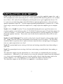
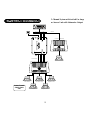
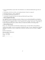
System Diagram
Left Front Center Front Right Front
Left Rear Right Rear
Center Channel
Switch Set to
“ON”
Not
Used
1k-20kHz
0dB +10dB
-10dB +10dB
1kHz
-10dB +10dB
250Hz
-10dB +10dB
Frequency
40Hz 80Hz
Subwoofer
Sub Volume
R Fader F
Volu me
Input
A/B
Sub Out
2-Channel or Mono Amp
5-Channel Amp
BAND
DISP AS
/
PS
LOUDMODE
MUTE
TUNE
123456
SEL
VOL
COMPACT DISC PLAYER WITH DIGITAL TUNER
RPT
TRACK
SCAN
RDM DISC
PUSH
SEEK
MENU
ST RPT RDMLOUDLOCAL
CD CHANGER CONTROL
5-Channel System with in dash Pre-Amp
or Source Unit with Subwoofer Output

13
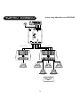
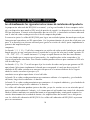
System Diagram
Left Front Center Front Right Front
Left Rear Right Rear
Center Channel
Switch Set to
“ON”
2-Channel or Mono Amp 5-Channel Amp
BAND
DISP AS
/
PS
LOUDMODE
MUTE
TUNE
123456
SEL
VOL
COMPACT DISC PLAYER WITH DIGITAL TUNER
RPT
TRACK
SCAN
RDM DISC
PUSH
SEEK
MENU
ST RPT RDMLOUDLOCAL
CD CHANGER CONTROL
System using Subwoofer out of RFQ5000

14
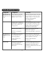
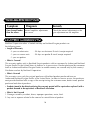
Troubleshooting
Symptom Diagnosis Remedy
RFQ5000 does not
turn on (Power LED
is off)
RFQ5000 has no
sound (Power LED
is on)
Voltage applied to the REM
terminal of the RFQ5000 is not
between 5 and 15.5 volts.
Check the alternator, battery, fuse and
wiring and repair as necessary. If the
voltage is above 15.5 volts, have the
electrical system inspected
by an authorized car
service center.
Voltage to the B+ terminal of
the RFQ5000 is not between 5
and 16 volts or there is no
voltage present.
Check the alternator, batter, fuse and
wiring and repair as necessary. If the
voltage is above 15.5 volts, have the
electrical system inspected by an
authorized car service center.
Internal B+ fuse is blown
Remove cover from RFQ5000 an
replace with 2 amp fuse.
RFQ5000 is not properly
grounded.
Check wiring and repair as necessary.
RCA Input from source unit
is not connected or not
functioning properly.
Check connections, substitute with
known working source and cables, and
repair or replaces as necessary.
Output attenuators are
at minimum.
Readjust output attenuators
as necessary.
Turn-On Pop
Voltage spike from output of
preceding component is
entering RFQ5000 through
input signal.
Disconnect input signal to RFQ5000
and turn unit on and off. If noise is
eliminated, connect REM lead of
RFQ5000 to remote turn-on wire with a
delay module.

Bad component in the
signal chain.
Check connections and bypass additional
components (crossovers and preamps)
between the source unit and the amplifier.
Connect one component at a time using
muting plugs (RCA signal shorted to
shield) at the input of each added compo-
nent to determine the culprit. Repair or
replace components as necessary.
Multiple grounds in the
audio system.
Check ground connections and connect
amplifiers, signal processors, and other
components to a central location or try a
different grounding point on the chassis.
The test signal
from the Set-up
CD does not
appear on the
correct channel
RCA out not properly
connected.
Check the RCA out from the RFQ5000
are going to the proper amp.
15
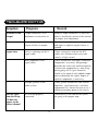
Troubleshooting
Symptom Diagnosis Remedy
Output attenuators set to
minimum or incorrectly set.
Readjust output attenuators as necessary.
Refer to Installation section of this manual
for proper level adjustment.
Source unit output too low or
source unit has no output.
Check system with known working source
and repair or replace original source as
needed.
Noise is radiating into RCA
signal cable.
Check connections and run the RCA
cables on a different route away from
sources of high current.
Distorted or Low
Output
Engine Noise

16
Troubleshooting
Symptom Diagnosis Remedy
One channel louder
than the others.
Internal amplifier adjustments
not correct.
Check the internal adjustment or the
gain adjustment on the amplifier
limited warranty
Rockford Corporation offers a limited warranty on Rockford Fosgate products on
the following terms:
•
Length of Warranty
- 3 years on electronics - 90 days on electronic B-stock (receipt required)
- 1 years on source units - 90 days on speaker B-stock (receipt required)
- 1 year on speakers
•
What is Covered
This warranty applies only to Rockford Fosgate products sold to consumers by Authorized Rockford
Fosgate Dealers in the United States of America or its possessions. Product purchased by consumers
from an Authorized Rockford Fosgate Dealer in another country are covered only by that country’s
Distributor and not by Rockford Corporation.
• Who is Covered
This warranty covers only the original purchaser of Rockford product purchased from an
Authorized Rockford Fosgate Dealer in the United States. In order to receive service, the purchaser
must provide Rockford with a copy of the receipt stating the customer name, dealer name, product
purchased and date of purchase.
• Products found to be defective during the warranty period will be repaired or replaced (with a
product deemed to be equivalent) at Rockford’s discretion.
• What is Not Covered
1. Damage caused by accident, abuse, improper operations, water, theft.
2. Any cost or expense related to the removal or reinstallation of product.

17
3. Service performed by anyone other than Rockford or an Authorized Rockford Fosgate Service
Center.
4. Any product which has had the serial number defaced, altered, or removed.
5. Subsequent damage to other components.
6. Any product purchased outside the U.S.
7. Any product not purchased from an Authorized Rockford Fosgate Dealer.
• Limit on Implied Warranties
Any implied warranties including warranties of fitness for use and merchantability are limited in
duration to the period of the express warranty set forth above. Some states do not allow limitations
on the length of an implied warranty, so this limitation may not apply. No person is authorized to
assume for Rockford Fosgate any other liability in connection with the sale of the product.
• How to Obtain Service
Please call 1-800-669-9899 for Rockford Customer Service. You must obtain an RA# (Return
Authorization number) to return any product to Rockford Fosgate. You are responsible for shipment
of product to Rockford. Always include Proof of Purchase and write RA# on outside of shipping
carton.
Rockford Corporation
Warranty Repair Department
2055 E. 5th Street
Tempe, AZ 85281
RA#:_________________

18
INSTALACION DEL RFQ5000 - ESPAÑOL
Lea detenidamente las siguientes instrucciones de instalación del producto.
La preparación adecuada del RFQ5000 es esencial, y se logra utilizando el disco compacto inclui-
do y un dispositivo para medir el SPL (nivel de presión de sonido). Los dispositivos de medición de
SPL que funcionan a batería están disponibles por tan sólo $50, y funcionarán en forma adecuada
con la señal de ruido rosado provista en el disco compacto de prueba.
Es necesario ajustar la salida del RFQ5000 para lograr un resultado óptimo, de modo que cada par-
lante principal reproduzca un SPL equivalente. Use los potenciómetros de ajuste de salida para este
paso. Si es necesario un alcance adicional para igualar los niveles de salida, ajuste simplemente la
ganancia del amplificador para
compensar.
Las bandas 1, 2, 3, 10 y 11 del disco compacto son señales de ruido rosado limitado por ancho de
banda que gira en una configuración en el sentido de las agujas del reloj en el orden siguiente: ID
– CD – DD – DT – CT (centro fantasma)-IT y luego se repite durante un total de cinco minutos.
Use estas bandas para asegurar que el procesador y los amplificadores están conectados a los
lugares de parlantes adecuados. Estas bandas también pueden utilizarse para confirmar el SPL rela-
tivo de cada lugar.
Las bandas 4, 9 y 12 a 17 se utilizan para fijar los niveles de cada canal para que generen un SPL
equivalente. Seleccione simplemente la banda que corresponda al canal que desea ajustar. El
medidor de SPL debe sostenerse en una posición que esté a la misma distancia de los lugares
desde los cuales escuchan el pasajero y el
conductor en un plano equivalente al nivel del oído.
La banda 18 es ruido rosado panorámico que comienza adelante a la izquierda y gira alrededor
del frente, luego finaliza adelante a la derecha.
La banda 19 es ruido rosado panorámico que comienza a la izquierda adelante y gira alrededor de
la parte posterior, luego finaliza adelante a la derecha.
Las salidas del subwoofer pueden ajustarse de oído, ya que los woofers no se ven afectados por el
proceso de sonido ambiental. Además, si el sistema que está utilizando tiene control de subwoofer
desde el tablero mediante una unidad de fuente o un preamplificador, usted puede conectar los
woofers directamente de la unidad de fuente a los amplificadores del woofer. No es obligatorio
usar las salidas del subwoofer del RFQ5000. Las salidas del subwoofer del RFQ5000 se proveen
para su conveniencia.

Cableado del conector
El terminal B+ debe ser conectado a una fuente no conmutada de 12V continuous. Prepare un
cable de la longitud adecuada desde la fuente de 12V+ y pele 1cm de aislante del cable en el
extremo que vaya a conectar al aparato. Inserte
el cable pelado en el orificio B+ del conector y asegúrelo con el tornillo.
NOTA: El terminal B+ de sistema de audio debe estar protegido con un fusible no más lejos de
45cm de la bateria. Instale un portafusibles y el correspondiente fusible en el compartimento del
motor. Las conexiones deben ser resistentes al agua.
El terminal REM ha de conectarse al terminal remote o antena de su radio-cassette. Prepare un
cable de la longitud adecuada desde la fuente y pele 1cm de aislante del cable en el extremo que
vaya a conectar al aparato. Inserte el cable pelado en el orificio REM del conector y asegúrelo con
el tornillo. El consumo
de corriente de este terminal es despriciable.
19
De ser posible, use cinco parlantes idénticos. Esto asegura que las calidades tonales de cada canal
sean similares, y las diferencias se puedan corregir fácilmente con la ecualización. Si no es posible
lograr que el canal central sea idéntico a los otros parlantes, use lo más parecido que tenga. La
calidad del parlante de canal central tendrá un gran efecto sobre la calidad general de sonido del
sistema.
Después de haber ajustado los cinco canales principales para igualar su nivel, puede luego experi-
mentar para encontrar el equilibrio entre canales que mejor funcione en su sistema. De acuerdo a
la ubicación de los parlantes, encontrará que la reducción o el aumento de la ganancia en algunos
canales produce un efecto más placentero.
En algunos sistemas, una reducción de la salida de alta frecuencia en los parlantes posteriores
puede mejorar la calidad general del sonido. Nuestra sugerencia es que comience con una ligera
reducción alrededor del extremo de 2-4 khz, y termine con una reducción de 6 dB en 20 khz. Esto
puede realizarse con una ecualización exterior. Si su sistema tiene una salida de subwoofer que se
controla desde el tablero del auto, puede enviar la señal del subwoofer directamente al amplifi-
cador o amplificadores del subwoofer. El RFQ5000 no tiene efecto sobre las bajas frecuencias y las
salidas del subwoofer son para ser utilizadas en sistemas sin salida de subwoofer delantera
controlada.
La pagina si sta caricando...
La pagina si sta caricando...
La pagina si sta caricando...
La pagina si sta caricando...
La pagina si sta caricando...
La pagina si sta caricando...
La pagina si sta caricando...
La pagina si sta caricando...
-
 1
1
-
 2
2
-
 3
3
-
 4
4
-
 5
5
-
 6
6
-
 7
7
-
 8
8
-
 9
9
-
 10
10
-
 11
11
-
 12
12
-
 13
13
-
 14
14
-
 15
15
-
 16
16
-
 17
17
-
 18
18
-
 19
19
-
 20
20
-
 21
21
-
 22
22
-
 23
23
-
 24
24
-
 25
25
-
 26
26
-
 27
27
-
 28
28


Rockford Fosgate RFQ5000 Setup Instructions
- Categoria
- Amplificatori audio per auto
- Tipo
- Setup Instructions
in altre lingue
- English: Rockford Fosgate RFQ5000
- français: Rockford Fosgate RFQ5000
- español: Rockford Fosgate RFQ5000
Documenti correlati
-
 Rockford Fosgate 4.6 Istruzioni per l'uso
-
 Rockford Fosgate Punch 100z2 Guida d'installazione
-
Rockford Fosgate PRIME R2-200X2 Manuale utente
-
 Rockford Fosgate 45.2 Manuale utente
-
 Rockford Fosgate Power 550S Istruzioni per l'uso
-
 Rockford Fosgate Punch P1000X5D Instructions Manual
-
Rockford R1200-1D Manuale utente
-
 Rockford Fosgate T8004 Manuale del proprietario


