www.videolarm.com
D e p u t y 2
Customizable Vandal-Resistant City Surveillance System
Installation and Operation Instructions for the following models:
D2BW1 Deputy2 Box with wall mount, support for up to 3 cameras. 110Vac input surge
protection, H&B system and 24Vac output to the camera. Space for user
installed electronics
D2BB1 Deputy2 battery backup kit for a 12Vdc cameras
D2LK1B Deputy2 ashing light kit, 1 long lasting Blue LED ashing light with mounting bar
for Deputy2 Box
D2LK2B Deputy2 ashing light kit, 2 long lasting Blue LED ashing light with mounting bar
for Deputy2 Box
Before attempting to connect or operate this product, please read these instructions completely.
81-IN5436
12-21-2011
© 2011, Moog Videolarm, Inc. All Rights Reserved

IMPORTANT SAFEGUARDS SAFETY PRECAUTIONS
UNPACKING
SERVICE
1 Read these instructions.
2 Keep these instructions.
3 Heed all warnings
4 Follow all instructions.
5 Do not use this apparatus near water.
6 Clean only with damp cloth.
7 Do not block any of the ventilation openings. Install in accordance with the
manufacturers instructions.
8 Cable Runs- All cable runs must be within permissible distance.
9 Mounting - This unit must be properly and securely mounted to a supporting
structure capable of sustaining the weight of the unit.
Accordingly:
a. The installation should be made by a qualied installer.
b. The installation should be in compliance with local codes.
c. Care should be exercised to select suitable hardware to install the unit, taking into
account both the composition of the mounting surface and the weight of the unit.
10 Do not install near any heat sources such as radiators, heat registers, stoves, or other
apparatus ( including ampliers) that produce heat.
11 Do not defeat the safety purpose of the polarized or grounding-type plug. A
polarized plug has two blades with one wider than the other. A grounding type
plug has two blades and a third grounding prong. The wide blade or the third
prong are provided for your safety. When the provided plug does not t into your
outlet, consult an electrician for replacement of the obsolete outlet.
12 Protect the power cord from being walked on or pinched particularly at plugs,
convenience receptacles, and the point where they exit from the apparatus.
13 Only use attachment/ accessories specied by the manufacturer.
14 Use only with a cart, stand, tripod, bracket, or table specied by the manufacturer,
or sold with the apparatus. When a cart is used, use caution when moving the cart/
apparatus combination to avoid injury from tip-over.
15 Unplug this apparatus during lighting storms or when unused for long periods of time.
16 Refer all servicing to qualied service personnel. Servicing is required when the
apparatus has been damaged in any way, such as power-supply cord or plug is
damaged, liquid has been spilled of objects have fallen into the apparatus, the
apparatus has been exposed to rain or moisture, does not operate normally, or
has been dropped.
Be sure to periodically examine the unit and the supporting structure to make sure that the integrity
of the installation is intact. Failure to comply with the foregoing could result in the unit separating
from the support structure and falling, with resultant damages or injury to anyone or anything struck
by the falling unit.
Unpack carefully. Electronic components can be
damaged if improperly handled or dropped. If an item
appears to have been damaged in shipment, replace
it properly in its carton and notify the shipper.
Be sure to save:
1 The shipping carton and packaging material.
They are the safest material in which to make future
shipments of the equipment.
2 These Installation and Operating Instructions.
If technical support or service is needed, contact us at
the following number:
The lightning ash with an arrowhead symbol,
within an equilateral triangle, is intended to
alert the user to the presence of non-insulated
“dangerous voltage” within the product’s
enclosure that may be of sufcient magnitude
to constitute a risk to persons.
Este símbolo se piensa para alertar al usuario a la presencia
del “voltaje peligroso no-aisIado” dentro del recinto de los
productos que puede ser un riesgo de choque eléctrico.
Ce symbole est prévu pour alerter I’utilisateur à la presence
“de la tension dangereuse” non-isolée dans la clôture de
produits qui peut être un risque de choc électrique.
Dieses Symbol soll den Benutzer zum Vorhandensein der
nicht-lsolier “Gefährdungsspannung” innerhalb der
Produkteinschließung alarmieren die eine Gefahr des
elektrischen Schlages sein kann.
Este símbolo é pretendido alertar o usuário à presença “di
tensão perigosa non-isolada” dentro do cerco dos produtos
que pode ser um risco de choque elétrico.
Questo simbolo è inteso per avvertire I’utente alla presenza
“di tensione pericolosa” non-isolata all’interno della
recinzione dei prodotti che può essere un rischio di scossa
elettrica
.
The exclamation point within an equilateral
triangle is intended to alert the user to
presence of important operating and
maintenance (servicing) instructions in the
literature accompanying the appliance.
Este símbolo del punto del exclamation se piensa para
alertar al usuario a la presencia de instrucciones importantes
en la literatura que acompaña la aplicación.
Ce symbole de point d’exclamation est prévu pour alerter
l’utilisateur à la presence des instructions importantes dans
la littérature accompagnant l’appareil.
Dieses Ausruf Punktsymbol soll den Benutzer zum
Vorhandensein de wichtigen Anweisungen in der Literatur
alarmieren, die das Gerät begleitet.
Este símbolo do ponto do exclamation é pretendido alertar o
usuário à presença de instruções importantes na literatura
que acompanha o dispositivo.
Questo simbolo del punto del exclamaton è inteso per
avvertire l’utente alla presenza delle istruzioni importanti nella
letteratura che accompagna l'apparecchio.
TECHNICAL SUPPORT
AVAILABLE 24 HOURS
1- 800 - 554 -1124
RISK OF ELECTRIC SHOCK
DO NOT OPEN
CAUTION
CAUTION: TO REDUCE THE RISK OF
ELECTRIC SHOCK, DO NOT REMOVE
COVER ( OR BACK). NO USER- SERVICE-
ABLE PARTS INSIDE. REFER SEVICING
TO QUALIFIED SERVICE PERSONNEL.

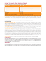
Limited Warranty for Moog Videolarm Products
Moog Videolarm warrants these products to be free from defects in material or workmanship as follows:
PRODUCT CATEGORY PARTS \ LABOR
All Enclosures and Electronics* Five (5) Years
Poles/PolEvators™/CamEvator Three (3) Years
Warrior Series™/Q-View™/IR Illuminators Five (5) Years
SView Series™ Five (5) Years **6 months if used in auto scan/tour operation
Controllers Five (5) Years
Power Supplies Five (5) Years
EcoKit Three (3) Years
Accessory Brackets Five (5) Years
Liberty Dome Three (3) Years
*DeputyDome™, NiteTrac™, Igloo Dome, PurgeDome™ Three (3) Years **6 months if used in auto scan/tour operation
During the labor warranty period, to repair the Product, Purchaser will either return the defective product, freight prepaid, or deliver it to Moog Videolarm
Inc. Decatur GA. The Product to be repaired is to be returned in either its original carton or a similar package affording an equal degree of protection with
a RMA # (Return Materials Authorization number) displayed on the outer box or packing slip. To obtain a RMA# you must contact our Technical Support
Team at 800.554.1124, extension 101. Moog Videolarm will return the repaired Product freight prepaid to Purchaser. Moog Videolarm is not obligated to
provide Purchaser with a substitute unit during the warranty period or at any time. After the applicable warranty period, Purchaser must pay all labor and/or
parts charges.
The limited warranty stated in these product instructions is subject to all of the following terms and conditions.
TERMS AND CONDITIONS
1. NOTIFICATION OF CLAIMS: WARRANTY SERVICE: If Purchaser believes that the Product is defective in material or workmanship, then written notice with an
explanation of the claim shall be given promptly by Purchaser to Moog Videolarm. All claims for warranty service must be made within the warranty period.
If after investigation Moog Videolarm determines the reported problem was not covered by the warranty, Purchaser shall pay Moog Videolarm for the cost of
investigating the problem at its then prevailing per incident billable rate. No repair or replacement of any Product or part thereof shall extend the warranty period
of the entire Product. The speci c warranty on the repaired part only shall be in effect for a period of ninety (90) days following the repair or replacement of that
part or the remaining period of the Product parts warranty, whichever is greater.
2. EXCLUSIVE REMEDY: ACCEPTANCE: Purchaser’s exclusive remedy and Moog Videolarm’s sole obligation is to supply (or pay for) all labor necessary to repair any
Product found to be defective within the warranty period and to supply, at no extra charge, new or rebuilt replacements for defective parts.
3. EXCEPTIONS TO LIMITED WARRANTY: Moog Videolarm shall have no liability or obligation to Purchaser with respect to any Product requiring service during the
warranty period which is subjected to any of the following: abuse, improper use, negligence, accident, lightning damage or other acts of God (i.e., hurricanes,
earthquakes), modi cation, failure of the end-user to follow the directions outlined in the product instructions, failure of the end-user to follow the maintenance
procedures recommended by the International Security Industry Organization, written in product instructions, or recommended in the service manual for the
Product. Furthermore, Moog Videolarm shall have no liability where a schedule is speci ed for regular replacement or maintenance or cleaning of certain parts
(based on usage) and the end-user has failed to follow such schedule; attempted repair by non-quali ed personnel; operation of the Product outside of the
published environmental and electrical parameters, or if such Product’s original identi cation (trademark, serial number) markings have been defaced, altered,
or removed. Moog Videolarm excludes from warranty coverage Products sold AS IS and/or WITH ALL FAULTS and excludes used Products which have not
been sold by Moog Videolarm to the Purchaser. All software and accompanying documentation furnished with, or as part of the Product is furnished “AS IS”
(i.e., without any warranty of any kind), except where expressly provided otherwise in any documentation or license agreement furnished with the Product. Any
cost associated with removal of defective product and installation of replacement product is not included in this warranty.
4. PROOF OF PURCHASE: The Purchaser’s dated bill of sale must be retained as evidence of the date of purchase and to establish warranty eligibility.
DISCLAIMER OF WARRANTY
EXCEPT FOR THE FOREGOING WARRANTIES, Moog Videolarm HEREBY DISCLAIMS AND EXCLUDES ALL OTHER WARRANTIES, EXPRESS OR IMPLIED,
INCLUDING, BUT NOT LIMITED TO ANY AND/OR ALL IMPLIED WARRANTIES OF MERCHANTABILITY, FITNESS FOR A PARTICULAR PURPOSE AND/OR
ANY WARRANTY WITH REGARD TO ANY CLAIM OF INFRINGEMENT THAT MAY BE PROVIDED IN SECTION 2-312(3) OF THE UNIFORM COMMERCIAL
CODE AND/OR IN ANY OTHER COMPARABLE STATE STATUTE. Moog Videolarm HEREBY DISCLAIMS ANY REPRESENTATIONS OR WARRANTY THAT
THE PRODUCT IS COMPATIBLE WITH ANY COMBINATION OF NON-Moog Videolarm PRODUCTS OR NON-Moog Videolarm RECOMMENDED PRODUCTS
PURCHASER MAY CHOOSE TO CONNECT TO THE PRODUCT.
LIMITATION OF LIABILITY
THE LIABILITY OF Moog Videolarm, IF ANY, AND PURCHASER’S SOLE AND EXCLUSIVE REMEDY FOR DAMAGES FOR ANY CLAIM OF ANY KIND
WHATSOEVER, REGARDLESS OF THE LEGAL THEORY AND WHETHER ARISING IN TORT OR CONTRACT, SHALL NOT BE GREATER THAN THE ACTUAL
PURCHASE PRICE OF THE PRODUCT WITH RESPECT TO WHICH SUCH CLAIM IS MADE. IN NO EVENT SHALL Moog Videolarm BE LIABLE TO PURCHASER
FOR ANY SPECIAL, INDIRECT, INCIDENTAL, OR CONSEQUENTIAL DAMAGES OF ANY KIND INCLUDING, BUT NOT LIMITED TO, COMPENSATION,
REIMBURSEMENT OR DAMAGES ON ACCOUNT OF THE LOSS OF PRESENT OR PROSPECTIVE PROFITS OR FOR ANY OTHER REASON WHATSOEVER.

Deputy2
Power 120 VAC
Energía 120 VAC
Puissance 120 VAC
Energie 120 VAC
Poder 120 VAC
Alimentazione 120 VAC
!!
Electrical & Mechanical Specifications
Français
Deutsch
Italiano
Portuguese
Español
English
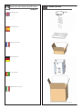
Content of Box
(X) 4
Note: Additional products may be included based around your purchase order

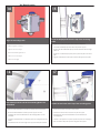
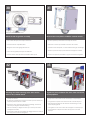
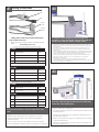
The Deputy2 can be mounted either on a pole or
surface
• El Deputy2 se puede montar en un poste o una superficie
• Le Deputy2 peut être monté sur un poteau ou une surface
• Das Deputy2 kann entweder an einem Pfosten oder an einer
Oberfläche angebracht werden
• O Deputy2 pode ser montado em um pólo ou em uma superfície
• Il Deputy2 può essere montato su un palo o su una superficie
Thread one retainer extrusion at the end of steel band,
allowing 1” (254mm) of band out. Beveled end of
extrusion to be out.
• Un hilo de retención de extrusión en la final de la banda de acero,
permitiendo 1 "(254 mm), de banda a cabo. Biselados final de
extrusión que se fuera.
• Thread extrusion une retenue à la fin de la bande d'acier, permettant
à 1 "(254mm) de la bande de. Biseauté fin de l'extrusion de ne pas être.
• Rijg een vasthoud-extrusie op het einde van stalen band, waardoor 1
"(254 mm) van de band uit. Schuine einde van de extrusie worden
uitgesloten.
• Passe um retentor extrusão no final da banda de aço, permitindo 1
"(254 milímetros), da banda fora. Biselado final de extrusão de ser fora.
• Iniziatore di estrusione uno fermo alla fine di banda di acciaio,
consentendo 1 "(254 millimetri) di banda fuori. Smussato fine di
estrusione di essere fuori.
2
Carefully bend steel band around beveled end of
extrusion. Hammer bend band to create a sharp
radius.
• Doblar cuidadosamente alrededor de banda de acero biselado final
de la extrusión. Libra doblado la banda para crear un plano de radio.
• Plier soigneusement autour de la bande d'acier biseautée fin de
l'extrusion. Livre bande pliée pour créer un plat de rayon.
• Buig stalen band rond schuine einde van extrusie. Pound gebogen
band voor het maken van een vlakke straal.
• Cuidadosamente dobre aço biselado fim da banda em torno de
extrusão. Libra curvados banda para criar um plano de raio.
• Attentamente piegare acciaio banda intorno smussato fine di
estrusione. Sterlina piegato banda per creare un piatto raggio.
3
Measure perimeters around pole at desired mounting location.
Measure band from outside edge of threaded retainer extrusion. Allow
for additional 1½” (254 mm) to be placed underneath additional
extrusion. Mark steel band and cut.
•
Medida de distancias en torno a polos de montaje en la ubicación deseada.
Medida de fuera de banda borde de la rosca de retención de extrusión. Dejar
para más 1½ "(254 mm), que se coloca debajo adicionales de extrusión. Marcos
de acero y banda de corte.
• Mesurer les distances autour de pôles de montage à l'emplacement désiré.
Mesure bande de bord extérieur de l'extrusion de retenue fileté. Pour permettre
supplémentaire de 1½ "(254 mm) pour être placées sous d'autres extrusion. Mark
bande d'acier et de coupe.
• Meet afstanden rond de paal te monteren gewenste locatie. Maatregel band van
buiten de rand van het threaded vasthoud-extrusie. Laat voor extra 1½ "(254 mm)
worden geplaatst onder meer extrusie. Mark stalen band en uitgesneden.
• Medida de distâncias de cerca de pólo na montagem local desejado. Medida
banda de fora de borda enfiada retentor extrusão. Permitir adicionais para 1½
"(254 mm) devem ser colocados debaixo adicionais extrusão. Mark banda de aço
e de corte.
• Misura le distanze intorno al polo di montaggio posizione desiderata. Misura banda
al di fuori del bordo del fermo filettati estrusione. Consenti per ulteriori 1½ "(254 mm)
ad essere messi sotto supplementari estrusione. Mark acciaio banda e taglio.
4
1
Pole Mount Assembly

Thread mounting hardware and additional retainer extrusion
at opposite end of steel band. Refer to Block 1 and 2 for
instructions.
• Rosca de montaje de hardware adicional y anticipo de extrusión en el
extremo opuesto de la banda de acero. Consulte a Bloque 1 y 2 para
obtener instrucciones.
• Thread matériel de montage et de retenue supplémentaire d'extrusion
à face en acier fin de bande. Reportez-vous à bloc 1 et 2 pour les
instructions.
• Rijg de montage van extra hardware en vasthoud-extrusie op het
andere uiteinde van stalen band. Raadpleeg Blok 1 en 2 voor
instructies.
• Rosca de montagem e hardware adicional retentor extrusão na
extremidade oposta da banda de aço. Referem-se Bloco 1 e 2 para
obter instruções.
• Iniziatore di montaggio e supplementari fermo estrusione a fine opposta
fascia di acciaio. Fare riferimento al blocco 1 e 2 per le istruzioni.
5
Place assembly around pole at desired mounting location.
Insert bolt through retainer extrusions. Head of bolt needs to
lock into end of retainer.
• Lugar de reunión en torno a polos de montaje en la ubicación deseada.
Inserte el perno de retención a través de extrusiones. Jefe de la saeta a las
necesidades de bloqueo en la final del retenedor.
• Lieu de rassemblement autour de pôles de montage à l'emplacement désiré.
Insérer boulon de retenue extrusions. Chef de boulon doit en fin de verrouil-
lage de la bague de retenue.
• Plaats vergadering rond de paal te monteren gewenste locatie. Plaats bout
door vasthoud extrusies. Hoofd van de bout moet vastklikken einde van
vasthoud.
• Colocar cerca de montagem em poste montagem local desejado. Inserir
ferrolho através retentor extrusões. Chefe do ferrolho precisa ser encaixado na
extremidade do dispositivo de retenção.
• Luogo di montaggio intorno al polo di montaggio posizione desiderata.
Inserire il bullone attraverso fermo estrusioni. Capo del bullone deve bloccare
in fine di fermo.
6
Thread nut to end of bolt and tighten with wrench.
• Hilo para poner fin a la tuerca de tornillo y apretar con llave.
• Thread noix à la fin de boulon et serrez avec clé.
• Thread moer tot het einde van de bout en draai met de moersleutel.
• Thread porca para o fim do ferrolho e aperte com a chave inglesa.
• Iniziatore dado alla fine del bullone e serrare con la chiave inglese.
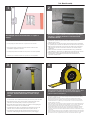
7
Pole Mount Assembly Continued

Installation is complete when nut is tight / secure and all slack has been removed from steel band.
• La instalación es completa cuando es apretado la tuerca / garantizar la seguridad de todos y la atonía se ha eliminado de la banda
de acero.
• L'installation est terminée lorsque l'écrou est serré, sécurité et tous les mou a été retiré de la bande d'acier.
• De installatie is volledig wanneer moer is strak / beveiligde en alle speling verwijderd is van staal-band.
• A instalação está completa quando porca é apertado / seguro e todos folga foi removido da banda de aço.
• L'installazione è completa quando il dado è stretto / e tutte le sicuro slack è stata rimossa dalla banda di acciaio.
8
Repeat for multiple band applications.
• Repetición para los usos de venda múltiples.
• Répétition pour des applications de bande multiples.
• Wiederholung für mehrfache Bandanwendungen.
• Repetição para aplicações de faixa múltiplas.
• Ripetizione per le applicazioni di fascia multiple.
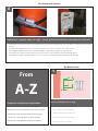
From
A-Z
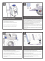
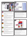
Locate and drill (4) holes 2” deep
• Localice y perfore (4) los agujeros 2” profundamente
• Trouvez et forez (4) les trous 2 » profondément
• Lokalisieren Sie und bohren Sie (4) Löcher 2“ tief
• Encontre e perfure (4) furos 2” profundamente
• Individui e perfori (4) fora 2„ in profondità
(4) holes
9
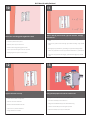
Wall Mount Assembly
Pole Mount Assembly Continued

Place the mounting plate against the wall
• Coloque la pletina contra la pared
• Placez le plat de support contre le mur
• Setzen Sie die Montageplatte gegen die Wand
• Coloc a placa de montagem de encontro à parede
• Disponga il giunto di supporto contro la parete
Attach with (4) anchor bolts, (4) lock washers, and (4)
flat washers
• Fijación con (4) los pernos de ancla, (4) arandelas de cerradura, y (4) arandelas
planas
• Attache avec (4) des boulons d'anchrage, (4) rondelles de freinage, et (4) rondelles
plates
• Befestigung mit (4) Ankerbolzen, (4) Federringe und (4) flache Unterlegscheiben
• Anexo com (4) parafusos de escora, (4) arruelas de fechamento, e (4) arruelas lisas
• Attaccatura con (4) bulloni d'ancoraggio, (4) ranelle di bloccaggio e (4) rondelle
piane
Tighten all bolts securely
• Apriete todos los pernos con seguridad
• Serrez tous les boulons solidement
• Ziehen Sie alle Schraubbolzen sicher fest
• Aperte todos os parafusos firmemente
• Stringa saldamente tutti i bulloni
Hang the Deputy2 unit onto the wall mount
• Cuelgue la unidad Deputy2 sobre el montaje de la pared
• Accrochez l'unité Deputy2 sur le bâti de mur
• Hängen Sie die Maßeinheit Deputy2 auf die Wandeinfassung
• Pendure a unidade Deputy2 na montagem da parede
• Appenda l'unità Deputy2 sul supporto della parete
11
13
10
12
Wall Mount Assembly Continued

Hook the Deputy2 unit onto the top of the mounting
plate
• Enganche la unidad Deputy2 sobre la tapa de la pletina
• Accrochez l'unité Deputy2 sur le dessus du plat de support
• Spannen Sie die Maßeinheit Deputy2 auf die Oberseite der Montage-
platte an
• Enganche a unidade Deputy2 na parte superior da placa de monta-
gem
• Agganci l'unità Deputy2 sulla parte superiore del giunto di supporto
Fasten the two bolts at the top of the mounting plate
• Sujete los dos pernos en la tapa de la pletina
• Attachez les deux boulons au dessus du plat de support
• Befestigen Sie die zwei Schraubbolzen an der Oberseite der
Montageplatte
• Prenda os dois parafusos na parte superior da placa de montagem
• Fissi i due bulloni alla parte superiore del giunto di supporto
Immediately bolt the unit to the mounting plate from
the bottom
• Emperne inmediatamente la unidad a la pletina de la parte inferior
• Boulonnez immédiatement l'unité au plat de support du fond
• Verriegeln Sie sofort die Maßeinheit an die Montageplatte von der
Unterseite
• Aparafuse imediatamente a unidade à placa de montagem da parte
inferior
• Immediatamente serri l'unità al giunto di supporto dalla parte inferiore
Align the mounting holes
• Alinee los agujeros de montaje
• Alignez les trous de montage
• Richten Sie die Entlüftungslöcher aus
• Alinhe os furos de montagem
• Allini i fori di montaggio
15
1716
14
Wall Mount Assembly

Completely tighten all four (4) bolts
• Apriete totalmente los cuatro (4) pernos
• Serrez complètement chacun des quatre (4) boulons
• Ziehen Sie vollständig alle vier (4) Schraubbolzen fest
• Aperte completamente todos os quatro (4) parafusos
• Completamente stringa tutti e quattro le (4) bulloni
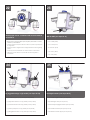
There are (2) water tight
3/4
” conduit fittings at the rear
of the box. If only one is needed an IP66 hole plug is
provided
• Hay (2) agua firmemente guarniciones de 3/4 las” conducto en la
parte posterior de la caja. Si se necesita solamente uno se proporciona
un enchufe del agujero IP66
• Il y a (2) l'eau fortement garnitures de 3/4 des » conduit à l'arrière de la
boîte. Si seulement un est nécessaire une prise du trou IP66 est fournie
• Es gibt (2) Wasser fest die Befestigungen mit 3/4“ Rohren an der
Rückseite des Kastens. Wenn nur man benötigt wird, wird ein Stecker
des Lochs IP66 zur Verfügung gestellt
• Há (2) água firmemente os encaixes de 3/4” de canalização na parte
traseira da caixa. Se somente um é necessário um plugue do furo IP66
está fornecido
• Ci è (2) acqua fortemente i montaggi del 3/4„ di condotto alla parte
posteriore della scatola. Se soltanto uno è necessario una spina del foro
IP66 è fornita
There are filters in the vent to keep out pests. To clean,
pull the filter out and flush with water
• Hay filtros en el respiradero para guardar hacia fuera a parásitos. Para
limpiar, tire del filtro hacia fuera y a ras de agua
• Il y a des filtres dans le passage pour empêcher d'entrer des parasites. Pour
nettoyer, tirez le filtre dehors et à affleurement avec de l'eau
• Es gibt Filter in der Entlüftungsöffnung, zum der Plagen abzuhalten. Um zu säubern,
ziehen Sie den Filter heraus und bündig mit Wasser
• Há filtros no respiradouro para manter para fora pragas. Para limpar, puxe o filtro
para fora e em nível com água
• Ci sono filtri nello sfiato per impedire di entrare i parassiti. Per pulire, tiri il filtro fuori ed
a livello di acqua
If no ventilation is required and an IP66 rating is desired
press fit end cap plugs are supplied
• Si no se requiere ninguna ventilación y se provee un grado IP66 es
tapones deseados de extremo del ajuste de prensa
• Si aucune ventilation n'est exigée et une estimation IP66 est les prises désirées de
monture d'ajustement de presse sont fournies
• Wenn keine Ventilation angefordert wird und eine Bewertung IP66 ist gewünschte
Einpreßendstöpselstecker werden geliefert
• Se nenhuma ventilação é exigida e uma avaliação IP66 é plugues de tampão
desejados da extremidade do ajuste de imprensa está fornecida
• Se nessuna ventilazione è richiesta e una valutazione IP66 è tappi voluti
dell'estremità di misura di pressa è fornita
18
19
20 21

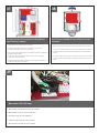
The Deputy2 can be customized with several cameras
and features
• El Deputy2 se puede modificar para requisitos particulares con varias
cámaras y características
• Le Deputy2 peut être adapté aux besoins du client avec plusieurs appareils-photo
et configurations
• Das Deputy2 kann mit einigen Kameras und Eigenschaften besonders angefertigt
werden
• O Deputy2 pode ser personalizado com diversas câmeras e características
• Il Deputy2 può essere adattato con parecchie macchine fotografiche e
caratteristiche
With an RM7 (see steps 26-31)
• Con un RM7 (26-31)
• Avec un RM7 (26-31)
• Wit einem RM7 (
26-31)
• Com um RM7 (
26-31)
• Con un RM7 (
26-31)
(2) rugged housings or (2) ACH13 (see steps 32-34)
• (2) cubiertas rugosas y un (2) ACH13 (see steps 32-34)
• (2) logements raboteux et un (2) ACH13 (see steps 32-34)
• (2) schroffe Gehäuse und ein (2) ACH13 (see steps 32-34)
• (2) carcaças ásperas e um (2) ACH13 (see steps 32-34)
• (2) alloggiamenti robusti e un (2) ACH13 (see steps 32-34)
Dual light features (see steps 42-47)
• Características ligeras duales (see steps 42-47)
• Dispositifs légers duels (see steps 42-47)
• Helle Verdoppelungeigenschaften (see steps 42-47)
• Características claras duplas (see steps 42-47)
• Caratteristiche chiare doppie (see steps 42-47)
22 23
24
25

RM7 installation
• Instalación RM7
• Installation RM7
• Installation RM7
• A instalação RM7
• Installazione RM7
Remove cover plate and gasket from the bottom of the
unit
• Quite la tapadera y la junta de la parte inferior de la unidad
• Enlevez le couvercle et la garniture du fond de l'unité
• Entfernen Sie Deckplatte und Dichtung von der Unterseite der
Maßeinheit
• Remova a placa e a gaxeta de tampa da parte inferior da unidade
• Rimuova il coperchio e la guarnizione dalla parte inferiore dell'unità
Place the RM7 housing into the unit oriented as shown
• Coloque la cubierta RM7 en la unidad orientada como se muestra
• Placez le logement RM7 dans l'unité orientée comme montrée
• Setzen Sie das Gehäuse RM7 in die Maßeinheit, die wie gezeigt
orientiert wird
• Coloc a carcaça RM7 na unidade orientada como mostrada
• Disponga l'alloggiamento RM7 nell'unità orientata come indicata
Tighten the (3) spring clamps
• Apriete (3) las abrazaderas del resorte
• Serrez (3) les brides de ressort
• Ziehen Sie die (3) Frühlingsklemmplatten fest
• Aperte (as 3) braçadeiras da mola
• Stringa (3) morsetti della molla
26
27
28
29

Attach the trim ring/dome assembly
• Ate el anillo del ajuste/el montaje de la bóveda
• Attachez l'anneau d'équilibre/dôme
• Bringen Sie den Ordnungsring/die Haube an
• Una o anel da guarnição/conjunto da abóbada
• Attacchi l'anello della disposizione/assemblea della cupola
Attaching the camera housing to the sides are the
same for any camera mount
• Atando la cámara que contiene a los lados sea iguales para cualquier
montaje de cámara
• En attachant l'appareil-photo logeant aux côtés soyez les mêmes pour
n'importe quelle monture de caméra
• Die Kamera, die zu den Seiten anbringend unterbringt, seien Sie die
selben für jede mögliche Kameraeinfassung
• Unindo a câmera que abriga aos lados seja o mesmos para toda a
montagem de câmera
• Attaccando la macchina fotografica che alloggia ai lati sia lo stessi per
tutto il supporto di macchina fotografica
A gasket is placed between the base of the mount and
the Deputy2 box
• Una junta se coloca entre la base del montaje y la caja Deputy2
• Une garniture est placée entre la base du bâti et la boîte Deputy2
• Eine Dichtung wird zwischen die Unterseite der Einfassung und den
Kasten Deputy2 gesetzt
• Uma gaxeta é coloc entre a base da montagem e a caixa Deputy2
• Una guarnizione è disposta fra la base del supporto e la scatola
Deputy2
Remove the cover plate to install the camera mounts
• Quite la tapadera para instalar los montajes de cámara
• Enlevez le couvercle pour installer les montures de caméra
• Entfernen Sie die Deckplatte, um die Kameraeinfassungen anzubringen
• Remova a placa de tampa para instalar as montagens de câmera
• Rimuova il coperchio per installare i supporti di macchina fotografica
30
31
32 33

Antennas and light can be installed on the side of the
Deputy2 Box. IP66 hole plugs are supplied for any
unused port (refer to blocks 42-47)
• Las antenas y la luz se pueden instalar en el lado de la caja Deputy2. Los enchufes
del agujero IP66 se suministran para cualquier puerto inusitado
• Des antennes et la lumière peuvent être installées du côté de la boîte Deputy2. Des
prises du trou IP66 sont fournies pour n'importe quel port inutilisé
• Antennen und Licht können auf die Seite des Kastens Deputy2 angebracht werden.
Stecker des Lochs IP66 werden für jeden unbenutzten Hafen geliefert
• As antenas e a luz podem ser instaladas no lado da caixa Deputy2. Os plugues do
furo IP66 são fornecidos para todo o porto não utilizado
• Le antenne e la luce possono essere installate dal lato della scatola Deputy2. Le
spine del foro IP66 sono fornite per tutto l'orificio inutilizzato
Electrical & Mechanical Specifications
Français
Deutsch
Italiano
Portuguese
Español
English
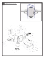
• Open packet assembly.
• Special ⅜” bolts are provided and designed to mount either
the WM20G or the WM10 (Standard Fusion Dome and
Rugged Housing wall mount bracket) to the Power box.
• Assemble wall mount bracket and housing as shown in the
next block.
• Push the cable assembly connectors through either of the
(2) holes provided.
• Abra el montaje de paquete.
• ⅜ rugoso del estándar especial se proporcionan y se diseñan
los” para montar el WM20G o el WM10 (pernos la bóveda
de la fusión y pared de la cubierta monta el soporte) a la
caja de la energía.
• Monte el soporte y la cubierta del montaje de la pared
según las indicaciones del bloque siguiente.
• Empuje los conectadores del montaje de cable con
cualquiera (2) de los agujeros proporcionados.
• Packet assembly ouvert.
• Le Special ⅜ » bolts l'are provided and designed to mount
either the WM20G or the WM10 (Standard Fusion Dome and
Rugged Housing wall mount bracket) to the Power le box.
• Assemble wall mount bracket and housing la cendre shown
dans the next block.
• Push the cable assembly connectors through either ou the (2)
holes provided.
• Öffnen Sie Paketierung.
• Spezielles ⅜“ Schraubbolzen sind, um entweder das WM20G
oder das WM10 (Standardbringen schmelzverfahrens-
Haube und schroffes Gehäusewand Haltewinkel), an zum
Energienkasten anzubringen zur Verfügung gestellt und
entworfen.
• Bauen Sie Wandeinfassungshaltewinkel und -gehäuse wie in
dem folgenden Block gezeigt zusammen.
• Drücken Sie die Kabelverbindungsstücke durch irgendein der
(2) bereitgestellten Löcher.
• Abra o conjunto de pacote.
• ⅜ áspero do padrão especial os” são fornecidos e projeta-
dos montar o WM20G ou o WM10 (parafusos a abóbada
da fusão e parede da carcaça monta o suporte) à caixa
do poder.
• Monte o suporte e a carcaça da montagem da parede
segundo as indicações do bloco seguinte.
• Empurre os conectores do conjunto de cabo com qualquer
um (2) dos furos fornecidos.
• Apra l'assemblea di pacchetto.
• ⅜ robusto dello standard speciale„ sono forniti e destinati per
montare il WM20G o il WM10 (i bulloni la cupola di fusione e
parete dell'alloggiamento monta la staffa) alla scatola di
potere.
• Monti la staffa e l'alloggiamento del supporto della parete
secondo le indicazioni del blocco seguente.
• Spinga i connettori dell'assemblea di cavo attraverso o del
(2) fori forniti.
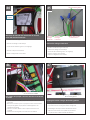
The (left) side electronics layout including optional
Battery backup installation
• La disposición lateral (dejada) de la electrónica incluyendo la
instalación opcional del respaldo de batería
• La disposition latérale (laissée) de l'électronique comprenant
l'installation facultative de support de batterie
• Der (gelassene) seitliche Elektronikplan einschließlich wahlweise
freigestellte Batterieaushilfsinstallation
• A disposição lateral (deixada) da eletrônica que inclui a instalação
opcional do apoio de bateria
• La disposizione laterale (lasciata) di elettronica compreso l'installazione
facoltativa del sostegno di batteria
Battery
Backup
34
35
36
Optional

Main power 120 VAC input.
• Alimentación principal 120 VAC de entrada
• Alimentation secteur 120 VCA d'entrée
• Netzspannung 120 VAC Eingang
• Poder principal 120 VAC de entrada
• Alimentazione di rete 120 VCA di input
The (right) side electronics layout including optional
Battery backup installation
• La disposición lateral (correcta) de la electrónica incluyendo la
instalación opcional del respaldo de batería
• (La bonne) disposition latérale de l'électronique comprenant
l'installation facultative de support de batterie
• Der (rechte) seitliche Elektronikplan einschließlich wahlweise freigestellte
Batterieaushilfsinstallation
• A disposição lateral (direita) da eletrônica que inclui a instalação
opcional do apoio de bateria
• (La giusta) disposizione laterale di elettronica compreso l'installazione
facoltativa del sostegno di batteria
The rear panel available for the customers electronic
equipment
• El panel trasero disponible para el equipo electrónico de los clientes
• Le panneau arrière disponible pour le matériel électronique de clients
• Das Rückwandblech vorhanden für die elektronische Ausrüstung der
Kunden
• O painel traseiro disponível para o equipamento eletrônico dos clientes
• Il pannello posteriore disponibile per l'apparecchiatura elettronica dei
clienti
37
38
39

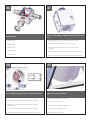
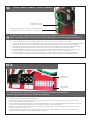
OUTPUT: 24VAC (Heater) 24VAC (Camera)
The Deputy 2 unit is supplied with three camera power control boards. These boards will convert the
120Vac input voltage down to 24Vac. It will also distribute the 24Vac to the camera and the heater/blowers
La unidad del diputado 2 se suministra tres tableros de control de energía de la cámara. Estos tableros convertirán el voltaje
de entrada 120Vac abajo a 24Vac. También distribuirá el 24Vac a la cámara y al calentador/a los sopladores
L'unité du député 2 est fournie avec trois tableaux de commande de puissance d'appareil-photo. Ces conseils convertiront la tension
d'entrée 120Vac vers le bas en 24Vac. Il distribuera également le 24Vac à l'appareil-photo et au réchauffeur/aux ventilateurs
Die Maßeinheit des Abgeordneten 2 wird mit drei Kameraenergien-Bedienpulten geliefert. Diese Bretter wandeln die Spannung
des Einganges 120Vac unten in 24Vac um. Es verteilt auch das 24Vac auf die Kamera und die Heizung/die Gebläse
A unidade do deputado 2 é fornecida com as três placas de controle do poder da câmera. Estas placas converterão a tensão
de entrada 120Vac para baixo a 24Vac. Igualmente distribuirá o 24Vac à câmera e ao calefator/ventiladores
L'unità del delegato 2 è fornita con tre bordi di controllo di potere della macchina fotografica. Questi bordi convertiranno
la tensione in ingresso 120Vac giù in 24Vac. Inoltre distribuirà il 24Vac alla macchina fotografica ed al riscaldatore/ventilatori
Auxiliary 24VAC output
connection (not fused)
Camera and heater/blower connection. Camera fused with
1 A resettable fuse. Heater fused with 4 A resettable fuses.
This connector block is used to aid the customer in managing and installing any need alarm
input or output for the camera system attached to the Deputy2
Este bloque de conectador se utiliza para ayudar al cliente en el manejo y la instalación cualquie necesita la alarma entrar o hacer
salir para el sistema de la cámara atado al Deputy2
Ce bornier est employé pour aider le client dans la gestion et l'installation toute a besoin d'alarme pour entrer ou produire pour le
système d'appareil-photo attaché au Deputy2
Dieser Verbindungsstückblock wird benutzt, um dem Kunden bei der Leitung zu helfen und die Installierung, die irgendeine ist, benötigt
Warnung, für das Kamerasystem einzugeben oder auszugeben, das zum Deputy2 angebracht wird
Este bloco de conector é usado para ajudar ao cliente no controlo e instalar alguma precisa o alarme de entrar ou output para o
sistema da câmera unido ao Deputy2
Questo blocchetto di connettore è usato per aiutare il cliente nel controllo e nell'installazione il tutto l'input o uscita dell'allarme di
bisogno per il sistema della macchina fotografica allegato al Deputy2
Connect alarms
from camera
Connect alarms
from head end
40
40-b

Make wire connection as they are required for your
needs
• Haga la conexión del alambre como se requieren para sus necesidades
• Établissez le rapport de fil comme ils sont exigés pour vos besoins
• Stellen Sie Drahtbeziehung her, wie sie für Ihre Notwendigkeiten
angefordert werden
• Faça a conexão do fio como são exigidos para suas necessidades
• Faccia il collegamento del legare come sono richiesti per i vostri bisogni
Wiring Instructions
Wiring Color Code Power and Control Inputs
RJ45
BNC
(Large)
Power
(Small)
Alarms
AFTER CAMERA INSTALLATION
Make inside housing wiring connections following Chart B
below.
Chart A Wiring Color Code
Power and Control Inputs (Outside of housing)
POWER
1 Camera Power Red
2 Camera Power Orange
3 Accessory Power Yellow
4 Accessory Power Green
CONTROL
RJ45 Ethernet Connector
ALARMS
eulB1 mralA1
teloiV 2 mralA2
yarG3 mralA3
etihWnommoC4
Chart B Power and Control Outputs (Inside of housing)
POWER
1 Camera Power Red
2 Camera Power Orange
ALARMS
eulB1 mralA1
teloiV 2 mralA2
yarG3 mralA3
etihWnommoC4
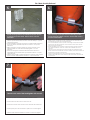
To install the optional light kit place the light-rack
assembly on top of the Deputy 2 Box and bolt with (4)
1/4-20 screws with lock washer and flat washer
• Para instalar el kit ligero opcional ponga el montaje del luz-estante encima del
diputado 2 caja y perno con (4) 1/4-20 tornillos con la arandela de cerradura y la
arandela plana
• Pour installer le kit léger facultatif placez le montage de lumière-support sur le
député 2 boîte et boulon avec (4) 1/4-20 vis avec la rondelle de freinage et la
rondelle plate
• Um den wahlweise freigestellten hellen Installationssatz anzubringen setzen Sie die
Lichtzahnstange Baugruppe auf den Abgeordneten 2 Kasten und Schraubbolzen
mit (4) 1/4-20 Schrauben mit Federring und flacher Unterlegscheibe
• Para instalar o jogo claro opcional coloc o conjunto da luz-cremalheira sobre o
deputado 2 caixa e parafuso com (os 4) 1/4-20 parafusos com arruela de
fechamento e a arruela lisa
• Per installare il corredo chiaro facoltativo disponga l'assemblea della
luce-cremagliera in cima al delegato 2 scatola e bullone con (4) 1/4-20 viti con la
ranella di bloccaggio e la rondella piana
Route the cable through the water proof conduit plug
on the side of the Deputy2 Box
• Encamine el cable a través del enchufe del conducto de la prueba del
agua en el lado de la caja Deputy2
• Conduisez le câble par la prise de conduit de preuve de l'eau du côté
de la boîte Deputy2
• Verlegen Sie das Kabel durch den Wasserbeweis-Rohrstecker auf der
Seite des Kastens Deputy2
• Distribua o cabo através do plugue da canalização da prova da água
no lado da caixa Deputy2
• Diriga il cavo tramite la spina del condotto della prova dell'acqua dal
lato della scatola Deputy2
41
42
43

Transformer
for light kit,
Mount the 24 VAC/24 VDC transformer to the side
panel with double sided tape
• Realice el cableado según lo indicado
• Exécutez le câblage comme indiqué
• Führen Sie die Verdrahtung durch, wie angezeigt
• Execute a fiação como indicado
• Effettui i collegamenti come indicato
Black Lead
from light
transformer
Red Lead
from light
transformer
Black , White and Red
Lead from Beacon
(2) Black
Lead from Flashing Button
Perform the wiring as indicated
• Realice el cableado según lo indicado
• Exécutez le câblage comme indiqué
• Führen Sie die Verdrahtung durch, wie angezeigt
• Execute a fiação como indicado
• Effettui i collegamenti come indicato
Purple and yellow connector plugs
into circuit board for 24 VDC
Plug yellow and purple connector into the circuit board
as shown
• Tape el conectador amarillo y púrpura en la tarjeta de circuitos como
se muestra
• Branchez le connecteur jaune et pourpre à la carte comme montrée
• Verstopfen Sie gelbes und purpurrotes Verbindungsstück in die
Leiterplatte wie gezeigt
• Obstrua o conector amarelo e roxo na placa de circuito como
mostrada
• Inserisca il connettore giallo e viola il circuito come indicato
Pushing in this button changes the
Beacon flashing pattern
Pushing the button changes the flashing pattern
• Empujar el botón cambia el patrón que destella
• La poussée du bouton change le modèle de clignotant
• Das Betätigen des Knopfes ändert das blinkende Muster
• Empurrar a tecla muda o teste padrão de piscamento
• La spinta del tasto cambia il modello infiammante
44
46
45
47

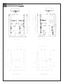
Deputy2
Replacement Parts List

Deputy2
Replacement Parts List
La pagina si sta caricando...
La pagina si sta caricando...
-
 1
1
-
 2
2
-
 3
3
-
 4
4
-
 5
5
-
 6
6
-
 7
7
-
 8
8
-
 9
9
-
 10
10
-
 11
11
-
 12
12
-
 13
13
-
 14
14
-
 15
15
-
 16
16
-
 17
17
-
 18
18
-
 19
19
-
 20
20
-
 21
21
-
 22
22