Genius Euro Breeze 06 Istruzioni per l'uso
- Tipo
- Istruzioni per l'uso

EURO BREEZE 06
EURO BREEZE 06

AVVERTENZE PER LíINSTALLATORE
OBBLIGHI GENERALI PER LA SICUREZZA
1) ATTENZIONE! È importante per la sicurezza delle persone seguire attenta-
mente tutta l’istruzione. Una errata installazione o un errato uso del prodotto
può portare a gravi danni alle persone.
2) Leggere attentamente le istruzioni prima di iniziare l’installazione del prodot-
to.
3) I materiali dell’imballaggio (plastica, polistirolo, ecc.) non devono essere
lasciati alla portata dei bambini in quanto potenziali fonti di pericolo.
4) Conservare le istruzioni per riferimenti futuri.
5) Questo prodotto è stato progettato e costruito esclusivamente per l’utilizzo
indicato in questa documentazione. Qualsiasi altro utilizzo non espressamente
indicato potrebbe pregiudicare l’integrità del prodotto e/o rappresentare
fonte di pericolo.
6) GENIUS declina qualsiasi responsabilità derivata dall’uso improprio o diverso
da quello per cui l’automatismo è destinato.
7) Non installare l’apparecchio in atmosfera esplosiva: la presenza di gas o fumi
infiammabili costituisce un grave pericolo per la sicurezza.
8) Gli elementi costruttivi meccanici devono essere in accordo con quanto
stabilito dalle Norme EN 12604 e EN 12605.
Per i Paesi extra-CEE, oltre ai riferimenti normativi nazionali, per ottenere un
livello di sicurezza adeguato, devono essere seguite le Norme sopra riporta-
te.
9) GENIUS non è responsabile dell’inosservanza della Buona Tecnica nella co-
struzione delle chiusure da motorizzare, nonché delle deformazioni che do-
vessero intervenire nell’utilizzo.
10) L’installazione deve essere effettuata nell’osservanza delle Norme EN 12453
e EN 12445. Il livello di sicurezza dell’automazione deve essere C+D.
11) Prima di effettuare qualsiasi intervento sull’impianto, togliere l’alimentazione
elettrica e scollegare le batterie.
12) Prevedere sulla rete di alimentazione dell’automazione un interruttore onni-
polare con distanza d’apertura dei contatti uguale o superiore a 3 mm. È
consigliabile l’uso di un magnetotermico da 6A con interruzione onnipolare.
13) Verificare che a monte dell’impianto vi sia un interruttore differenziale con
soglia da 0,03 A.
14) Verificare che l’impianto di terra sia realizzato a regola d’arte e collegarvi le
parti metalliche della chiusura.
15) L’automazione dispone di una sicurezza intrinseca antischiacciamento costi-
tuita da un controllo di coppia. E' comunque necessario verificarne la sogli di
intervento secondo quanto previsto dalle Norme indicate al punto 10.
16) I dispositivi di sicurezza (norma EN 12978) permettono di proteggere eventuali
aree di pericolo da Rischi meccanici di movimento, come ad Es. schiaccia-
mento, convogliamento, cesoiamento.
17) Per ogni impianto è consigliato l’utilizzo di almeno una segnalazione luminosa
nonché di un cartello di segnalazione fissato adeguatamente sulla struttura
dell’infisso, oltre ai dispositivi citati al punto “16”.
18) GENIUS declina ogni responsabilità ai fini della sicurezza e del buon funziona-
mento dell’automazione, in caso vengano utilizzati componenti dell’impian-
to non di produzione GENIUS.
19) Per la manutenzione utilizzare esclusivamente parti originali GENIUS.
20) Non eseguire alcuna modifica sui componenti facenti parte del sistema
d’automazione.
21) L’installatore deve fornire tutte le informazioni relative al funzionamento
manuale del sistema in caso di emergenza e consegnare all’Utente utilizzato-
re dell’impianto il libretto d’avvertenze allegato al prodotto.
22) Non permettere ai bambini o persone di sostare nelle vicinanze del prodotto
durante il funzionamento.
23) Tenere fuori dalla portata dei bambini radiocomandi o qualsiasi altro datore
di impulso, per evitare che l’automazione possa essere azionata involontaria-
mente.
24) Il transito tra le ante deve avvenire solo a cancello completamente aperto.
25) L’utente utilizzatore deve astenersi da qualsiasi tentativo di riparazione o
d’intervento e deve rivolgersi solo ed esclusivamente a personale qualificato
GENIUS o centri d’assistenza GENIUS.
26) Tutto quello che non è previsto espressamente in queste istruzioni non è
permesso
IMPORTANT NOTICE FOR THE INSTALLER
GENERAL SAFETY REGULATIONS
1) ATTENTION! To ensure the safety of people, it is important that you read all
the following instructions. Incorrect installation or incorrect use of the
product could cause serious harm to people.
2) Carefully read the instructions before beginning to install the product.
3) Do not leave packing materials (plastic, polystyrene, etc.) within reach of
children as such materials are potential sources of danger.
4) Store these instructions for future reference.
5) This product was designed and built strictly for the use indicated in this
documentation. Any other use, not expressly indicated here, could compro-
mise the good condition/operation of the product and/or be a source of
danger.
6) GENIUS declines all liability caused by improper use or use other than that for
which the automated system was intended.
7) Do not install the equipment in an explosive atmosphere: the presence of
inflammable gas or fumes is a serious danger to safety.
CONSIGNES POUR L'INSTALLATEUR
R»GLES DE S…CURIT…
1) ATTENTION! Il est important, pour la sécurité des personnes, de suivre à la
lettre toutes les instructions. Une installation erronée ou un usage erroné
du produit peut entraîner de graves conséquences pour les personnes.
2) Lire attentivement les instructions avant d'installer le produit.
3) Les matériaux d'emballage (matière plastique, polystyrène, etc.) ne doivent
pas être laissés à la portée des enfants car ils constituent des sources
potentielles de danger.
4) Conserver les instructions pour les références futures.
5) Ce produit a été conçu et construit exclusivement pour l'usage indiqué dans
cette documentation. Toute autre utilisation non expressément indiquée
pourrait compromettre l'intégrité du produit et/ou représenter une source
de danger.
6) GENIUS décline toute responsabilité qui dériverait d'usage impropre ou
différent de celui auquel l'automatisme est destiné.
7) Ne pas installer l'appareil dans une atmosphère explosive: la présence de
gaz ou de fumées inflammables constitue un grave danger pour la sécurité.
8) Les composants mécaniques doivent répondre aux prescriptions des Normes
EN 12604 et EN 12605.
Pour les Pays extra-CEE, l'obtention d'un niveau de sécurité approprié exige
non seulement le respect des normes nationales, mais également le respect
des Normes susmentionnées.
9) GENIUS n'est pas responsable du non-respect de la Bonne Technique dans la
construction des fermetures à motoriser, ni des déformations qui pourraient
intervenir lors de l'utilisation.
10) L'installation doit être effectuée conformément aux Normes EN 12453 et EN
12445. Le niveau de sécurité de l'automatisme doit être C+D.
11) Couper l'alimentation électrique et déconnecter la batterie avant toute
intervention sur l'installation.
12) Prévoir, sur le secteur d'alimentation de l'automatisme, un interrupteur
omnipolaire avec une distance d'ouverture des contacts égale ou supérieure
à 3 mm. On recommande d'utiliser un magnétothermique de 6A avec
interruption omnipolaire.
13) Vérifier qu'il y ait, en amont de l'installation, un interrupteur différentiel avec
un seuil de 0,03 A.
14) Vérifier que la mise à terre est réalisée selon les règles de l'art et y connecter
les pièces métalliques de la fermeture.
15) L'automatisme dispose d'une sécurité intrinsèque anti-écrasement, formée
d'un contrôle du couple. Il est toutefois nécessaire d'en vérifier le seuil
d'intervention suivant les prescriptions des Normes indiquées au point 10.
16) Les dispositifs de sécurité (norme EN 12978) permettent de protéger des
zones éventuellement dangereuses contre les Risques mécaniques du
mouvement, comme l'écrasement, l'acheminement, le cisaillement.
8) The mechanical parts must conform to the provisions of Standards EN 12604
and EN 12605.
For non-EU countries, to obtain an adequate level of safety, the Standards
mentioned above must be observed, in addition to national legal regulations.
9) GENIUS is not responsible for failure to observe Good Technique in the
construction of the closing elements to be motorised, or for any deformation
that may occur during use.
10) The installation must conform to Standards EN 12453 and EN 12445. The safety
level of the automated system must be C+D.
11) Before attempting any job on the system, cut out electrical power and
disconnect the batteries.
12) The mains power supply of the automated system must be fitted with an all-
pole switch with contact opening distance of 3mm or greater. Use of a 6A
thermal breaker with all-pole circuit break is recommended.
13) Make sure that a differential switch with threshold of 0.03 A is fitted upstream
of the system.
14) Make sure that the earthing system is perfectly constructed, and connect
metal parts of the means of the closure to it.
15) The automated system is supplied with an intrinsic anti-crushing safety device
consisting of a torque control. Nevertheless, its tripping threshold must be
checked as specified in the Standards indicated at point 10.
16) The safety devices (EN 12978 standard) protect any danger areas against
mechanical movement Risks, such as crushing, dragging, and shearing.
17) Use of at least one indicator-light is recommended for every system, as well
as a warning sign adequately secured to the frame structure, in addition to
the devices mentioned at point “16”.
18) GENIUS declines all liability as concerns safety and efficient operation of the
automated system, if system components not produced by GENIUS are used.
19) For maintenance, strictly use original parts by GENIUS.
20) Do not in any way modify the components of the automated system.
21) The installer shall supply all information concerning manual operation of the
system in case of an emergency, and shall hand over to the user the warnings
handbook supplied with the product.
22) Do not allow children or adults to stay near the product while it is operating.
23) Keep remote controls or other pulse generators away from children, to
prevent the automated system from being activated involuntarily.
24) Transit through the leaves is allowed only when the gate is fully open.
25) The end user has to be refrained to any tempted of repairing end he mast
contact only qualified Genius’ s personnel, or Genius’s technical after sale
offices.
26) Anything not expressly specified in these instructions is not permitted.

ADVERTENCIAS PARA EL INSTALADOR
REGLAS GENERALES PARA LA SEGURIDAD
1) ¡ATENCION! Es sumamente importante para la seguridad de las personas
seguir atentamente las presentes instrucciones. Una instalación incorrecta
o un uso impropio del producto puede causar graves daños a las personas.
2) Lean detenidamente las instrucciones antes de instalar el producto.
3) Los materiales del embalaje (plástico, poliestireno, etc.) no deben dejarse al
alcance de los niños, ya que constituyen fuentes potenciales de peligro.
4) Guarden las instrucciones para futuras consultas.
5) Este producto ha sido proyectado y fabricado exclusivamente para la
utilización indicada en el presente manual. Cualquier uso diverso del previsto
podría perjudicar el funcionamiento del producto y/o representar fuente de
peligro.
6) GENIUS declina cualquier responsabilidad derivada de un uso impropio o diverso del
previsto.
7) No instalen el aparato en atmósfera explosiva: la presencia de gas o humos
inflamables constituye un grave peligro para la seguridad.
8) Los elementos constructivos mecánicos deben estar de acuerdo con lo
establecido en las Normas EN 12604 y EN 12605.
Para los países no pertenecientes a la CEE, además de las referencias
normativas nacionales, para obtener un nivel de seguridad adecuado, deben
seguirse las Normas arriba indicadas.
9) GENIUS no es responsable del incumplimiento de las buenas técnicas de fabricación
de los cierres que se han de motorizar, así como de las deformaciones que pudieran
intervenir en la utilización.
10) La instalación debe ser realizada de conformidad con las Normas EN 12453 y
EN 12445. El nivel de seguridad de la automación debe ser C+D.
11) Quiten la alimentación eléctrica y desconecten las baterías antes de efectuar
cualquier intervención en la instalación.
12) Coloquen en la red de alimentación de la automación un interruptor
omnipolar con distancia de apertura de los contactos igual o superior a 3 mm.
Se aconseja usar un magnetotérmico de 6A con interrupción omnipolar.
13) Comprueben que la instalación disponga línea arriba de un interruptor
diferencial con umbral de 0,03 A.
14) Verifiquen que la instalación de tierra esté correctamente realizada y
conecten las partes metálicas del cierre.
15) La automación dispone de un dispositivo de seguridad antiaplastamiento
constituido por un control de par. No obstante, es necesario comprobar el
umbral de intervención según lo previsto en las Normas indicadas en el punto
10.
16) Los dispositivos de seguridad (norma EN 12978) permiten proteger posibles
áreas de peligro de Riesgos mecánicos de movimiento, como por ej.
aplastamiento, arrastre, corte.
17) Para cada equipo se aconseja usar por lo menos una señalización luminosa
así como un cartel de señalización adecuadamente fijado a la estructura del
bastidor, además de los dispositivos indicados en el “16”.
18) GENIUS declina toda responsabilidad relativa a la seguridad y al buen funcionamiento
de la automación si se utilizan componentes de la instalación que no sean de
producción GENIUS.
19) Para el mantenimiento utilicen exclusivamente piezas originales GENIUS
20) No efectúen ninguna modificación en los componentes que forman parte
del sistema de automación.
21) El instalador debe proporcionar todas las informaciones relativas al
funcionamiento del sistema en caso de emergencia y entregar al usuario del
equipo el manual de advertencias que se adjunta al producto.
22) No permitan que niños o personas se detengan en proximidad del producto
durante su funcionamiento.
23) Mantengan lejos del alcance los niños los telemandos o cualquier otro emisor
de impulso, para evitar que la automación pueda ser accionada
involuntariamente.
24) Sólo puede transitarse entre las hojas si la cancela está completamente
abierta.
HINWEISE F‹R DEN INSTALLATIONSTECHNIKER
ALLGEMEINE SICHERHEITSVORSCHRIFTEN
1) ACHTUNG! Um die Sicherheit von Personen zu gewährleisten, sollte die
Anleitung aufmerksam befolgt werden. Eine falsche Installation oder ein
fehlerhafter Betrieb des Produktes können zu schwerwiegenden
Personenschäden führen.
2) Bevor mit der Installation des Produktes begonnen wird, sollten die Anleitungen
aufmerksam gelesen werden.
3) Das Verpackungsmaterial (Kunststoff, Styropor, usw.) sollte nicht in Reichweite
von Kindern aufbewahrt werden, da es eine potentielle Gefahrenquelle
darstellt.
4) Die Anleitung sollte aufbewahrt werden, um auch in Zukunft Bezug auf sie nehmen zu
können.
5) Dieses Produkt wurde ausschließlich für den in diesen Unterlagen angegebenen
Gebrauch entwickelt und hergestellt. Jeder andere Gebrauch, der nicht ausdrücklich
angegeben ist, könnte die Unversehrtheit des Produktes beeinträchtigen und/oder
eine Gefahrenquelle darstellen.
6) Die Firma GENIUS lehnt jede Haftung für Schäden, die durch unsachgemäßen
oder nicht bestimmungsgemäßen Gebrauch der Automatik verursacht
werden, ab.
7) Das Gerät sollte nicht in explosionsgefährdeten Umgebungen installiert werden: das
Vorhandensein von entflammbaren Gasen oder Rauch stellt ein schwerwiegendes
Sicherheitsrisiko dar.
8) Die mechanischen Bauelemente müssen den Anforderungen der Normen EN
12604 und EN 12605 entsprechen.
Für Länder, die nicht der Europäischen Union angehören, sind für die
Gewährleistung eines entsprechenden Sicherheitsniveaus neben den
nationalen gesetzlichen Bezugsvorschriften die oben aufgeführten Normen
zu beachten.
9) Die Firma GENIUS übernimmt keine Haftung im Falle von nicht fachgerechten
Ausführungen bei der Herstellung der anzutreibenden Schließvorrichtungen
sowie bei Deformationen, die eventuell beim Betrieb entstehen.
10) Die Installation muß unter Beachtung der Normen EN 12453 und EN 12445
erfolgen. Die Sicherheitsstufe der Automatik sollte C+D sein.
11) Vor der Ausführung jeglicher Eingriffe auf der Anlage sind die elektrische
Versorgung und die Batterie abzunehmen.
12) Auf dem Versorgungsnetz der Automatik ist ein omnipolarer Schalter mit
Öffnungsabstand der Kontakte von über oder gleich 3 mm einzubauen.
Darüber hinaus wird der Einsatz eines Magnetschutzschalters mit 6A mit
omnipolarer Abschaltung empfohlen.
13) Es sollte überprüft werden, ob vor der Anlage ein Differentialschalter mit einer
Auslöseschwelle von 0,03 A zwischengeschaltet ist.
14) Es sollte überprüft werden, ob die Erdungsanlage fachgerecht ausgeführt
wurde. Die Metallteile der Schließung sollten an diese Anlage angeschlossen
werden.
15) Die Automation verfügt über eine eingebaute Sicherheitsvorrichtung für den
Quetschschutz, die aus einer Drehmomentkontrolle besteht. Es ist in jedem Falle
erforderlich, deren Eingriffsschwelle gemäß der Vorgaben der unter Punkt 10
angegebenen Vorschriften zu überprüfen.
16) Die Sicherheitsvorrichtungen (Norm EN 12978) ermöglichen den Schutz
eventueller Gefahrenbereiche vor mechanischen Bewegungsrisiken, wie
zum Beispiel Quetschungen, Mitschleifen oder Schnittverletzungen.
17) Für jede Anlage wird der Einsatz von mindestens einem Leuchtsignal empfohlen sowie
eines Hinweisschildes, das über eine entsprechende Befestigung mit dem Aufbau des
Tors verbunden wird. Darüber hinaus sind die unter Punkt “16” erwähnten Vorrichtungen
einzusetzen.
18) Die Firma GENIUS lehnt jede Haftung hinsichtlich der Sicherheit und des
störungsfreien Betriebs der Automatik ab, soweit Komponenten auf der Anlage
eingesetzt werden, die nicht im Hause GENIUS hergestellt wurden.
19) Bei der Instandhaltung sollten ausschließlich Originalteile der Firma GENIUS verwendet
werden.
20) Auf den Komponenten, die Teil des Automationssystems sind, sollten keine
Veränderungen vorgenommen werden.
21) Der Installateur sollte alle Informationen hinsichtlich des manuellen Betriebs
des Systems in Notfällen liefern und dem Betreiber der Anlage das
Anleitungsbuch, das dem Produkt beigelegt ist, übergeben.
22) Weder Kinder noch Erwachsene sollten sich während des Betriebs in der
unmittelbaren Nähe der Automation aufhalten.
23) Die Funksteuerungen und alle anderen Impulsgeber sollten außerhalb der Reichweite
von Kindern aufbewahrt werden, um ein versehentliches Aktivieren der Automation zu
vermeiden.
24) Der Durchgang oder die Durchfahrt zwischen den Flügeln darf lediglich bei
vollständig geöffnetem Tor erfolgen.
25) Der Benutzer muss sich enthalten von jegliche Reparatur versuch oder eingriff
und muss sich anschließlich an qualifizierte GENIUS personal wenden oder an
autorisierte GENIUS Kundendienststellen.
26) Alle Vorgehensweisen, die nicht ausdrücklich in der vorliegenden Anleitung
vorgesehen sind, sind nicht zulässig
17) On recommande que toute installation soit doté au moins d'une signalisation
lumineuse, d'un panneau de signalisation fixé, de manière appropriée, sur la
structure de la fermeture, ainsi que des dispositifs cités au point “16”.
18) GENIUS décline toute responsabilité quant à la sécurité et au bon
fonctionnement de l'automatisme si les composants utilisés dans l'installation
n'appartiennent pas à la production GENIUS.
19) Utiliser exclusivement, pour l'entretien, des pièces GENIUS originales.
20) Ne jamais modifier les composants faisant partie du système d'automatisme.
21) L'installateur doit fournir toutes les informations relatives au fonctionnement
manuel du système en cas d'urgence et remettre à l'Usager qui utilise
l'installation les "Instructions pour l'Usager" fournies avec le produit.
22) Interdire aux enfants ou aux tiers de stationner près du produit durant le
fonctionnement.
23) Eloigner de la portée des enfants les radiocommandes ou tout autre générateur
d'impulsions, pour éviter tout actionnement involontaire de l'automatisme.
24) Le transit entre les vantaux ne doit avoir lieu que lorsque le portail est
complètement ouvert.
25) Ne pas chercher à réparer ou à intervenir sur le produit. L’utilisateur doit faire
appel uniquement aux techniciens Genius ou au centre d’assistance technique
Genius.
26) Tout ce qui n'est pas prévu expressément dans ces instructions est interdit.
25) El utilizador no tiene que intentar reparaciones o intervenciones y tiene que
contactar solamente personal encargado GENIUS o centros autorizados
GENIUS.
26) Todo lo que no esté previsto expresamente en las presentes instrucciones
debe entenderse como no permitido

6
ENGLISH
CE DECLARATION OF CONFORMITY FOR MACHINES
(DIRECTIVE 98/37/CE)
Manufacturer: GENIUS S.p.A.
Address: Via Padre Elzi, 32 - 24050 - Grassobbio BERGAMO - ITALY
Declares that: EURO BREEZE 06 - EURO BREEZE 06 C - EURO BREEZE 06 24V mod. operator
• is built to be integrated into a machine or to be assembled with other machinery to create a machine under the provisions of
Directive 98/37/CE;
• conforms to the essential safety requirements of the following EEC directives:
73/23 EEC and subsequent amendment 93/68/EEC.
89/336 EEC and subsequent amendment 92/31/EEC and 93/68/EEC
and also declares that the machinery must not be put into service until the machine in which it will be integrated or of which it will
become a component has been identified and declared as conforming to the provisions of Directive 98/37/CE.
Grassobbio, 01-06-2006
The Managing Director
D.Gianantoni
INDEX
1. DESCRIPTION AND TECHNICAL SPECIFICATIONS pag.7
3. ELECTRICAL INSTALLATION LAYOUT (standard system) pag.7
2. DIMENSIONS pag.7
4. INSTALLING THE AUTOMATION SYSTEM pag.8
4.1. PRELIMINARY CHECKS pag.8
4.2. POSITIONING TELESCOPIC ARMS pag.8
4.3. POSITIONING OPERATOR/BACK PLATE pag.8
4.4. ASSEMBLY SEQUENCE pag.8
4.5. ADJUSTING THE COUNTERWEIGHTS pag.9
5. MOUNTING GEARED MOTOR UNIT pag.9
6. START-UP pag.9
6.1. CONNECTING ELECTRONIC CARD pag.9
7. TESTING THE AUTOMATION SYSTEM pag.10
8. MANUAL OPERATION pag.10
9. RETURNING TO NORMAL OPERATION pag.10
10. MAINTENANCE pag.10
11. REPAIRS pag.10
Notes on reading the instruction
Read this installation manual to the full before you begin installing the product.
The symbol indicates notes that are important for the safety of persons and for the good condition of the automated system
The symbol draws your attention to the notes on the characteristics and operation of the product.

7
ENGLISH
2x1.5
3x0.5
2x1.5 + GROUND
2x0.5
2x0.5
4x0.5
2x1.5
3x0.5
2x0.5
2x0.5
4x0.5
5x1.5 + GROUND
2x1.5 + GROUND
3
1
4
5
5
6
1
2
3
4
5
5
6
1
2
3
4
5
6
7
8
9
10
100
175
50
115
685
1300 - 1500 - 2000
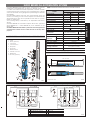
EURO BREEZE 06 AUTOMATION SYSTEM
The EURO BREEZE 06 automation system is designed to operate
residential counterbalanced up-and-over garage doors.
It consists of an electromechanical operator, a control unit with
courtesy light and a protective cover integrated into a single
unit to be mounted on the garage door panel using the relevant
accessories.
The irreversible system locks the door mechanically when the
motor is not running, so a lock is not required. A manual release
device allows the door to be operated in the case of a power
failure or malfunction.
Anti-crushing safety is assured by an adjustable electronic
device.
The EURO BREEZE 06 automation system allows two operators
(EURO BREEZE 06 C + EURO BREEZE 06) to be installed on the
same door.
The EURO BREEZE 06 automation system has been designed and
constructed for vehicle access control. Do not use for any other
purpose.
TABLE. 1 GEARED MOTOR TECHNICAL SPECIFICATIONS
2. DIMENSIONS
3. ELECTRICAL INSTALLATION LAYOUT (standard system)
• values in mm
1. DESCRIPTION AND TECHNICAL SPECIFICATIONS
LEDOM
60EZEERBORUE
otnelV032 V032 V42
ylppusrewoP zH05~V032cdV42
noitpmusnocrewoP W082W053W07
wardtnerruC A2.1A5.1A3
euqrot.xaM mN052mN003mN052
roticap
acegruS V004Fµ8V004Fµ01/
gnidniwnotuotuclamrehT C°041/
deepsrotoM nim/g009nim/g0041
oitarnoitcudeR 007:1
yticolev
ralugnA ces/°8ces/°21
3SelcycytuD %03%001
ruoh/selcyC
)hctiwstimiltuohtiw(02
)hctiwstimilhtiw(03
05
egnarerutar
epmeT C°55+/C°02-
rood.xaM
)m(htdiw
rotarepo13.33
srotarepo254
)m(thgiehrood.xaM 3
thgiewrood.xaM m/gK01
2
thgiewrotarepO gK5.7
noitcetorpgnisuoH
13PI
)sdractuohtiw(44PI
snoisnemidrotarepO 2.gifees
1revoC
2)lanoitpo(nottuB
3tinulortnoC
4xobtinulortnoC
5etalpkcaB
6tfahsevirD
7ecivedesaeleR
8tinurotomderaeG
9yekesael
eR
01)lanoitpo(redocnE
1rotarepoC60EZEERBORUE4hctiwsyeK
2rotarepo60EZEERBORUE5sllecotohP
3thgilgnihsalF6egdeytefaS
²mmnidesserpxeerasnoi
tces-ssorcelbacehT•
FIG.1
F
IG.2
F
IG.3

8
ENGLISH
A
B
C
S1
S2
=
=
=
=
~10cm
~10cm
~10cm
A
B
=
=
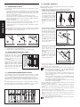
4. INSTALLING THE AUTOMATION SYSTEM
4.1. PRELIMINARY CHECKS
To ensure safe, proper operation of the automation system, check
the following:
• The door’s structure must be suitable for automation. Make
particularly sure that dimensions of the door meet the
requirements given in the technical specifications and that
the door is sufficiently robust.
• Check the condition of the door bearings and joints.
• Check that the door moves smoothly; If necessary clean the
tracks and lubricate them with a silicone based lubricant.
Do not use grease.
• Check that the door is correctly balanced.
• Remove the mechanical door locks so that when the door is
closed it is locked only by the automation system.
• Check that there is an effective earth connection for the
geared motor.
The EURO BREEZE 06 automation system is designed to operate
various types of counterbalanced up-and-over garage doors.
Fig. 4 shows the most common types:
a) single section outward swinging
b) double section outward swinging
c) single section inward swinging with horizontal tracks
4.3. POSITIONING OPERATOR/BACK PLATE
In accordance with the measurements given in Table 1, install
either a single operator at the centre of the door as shown in fig.
6 or two operators at the sides of the door as shown in fig. 7.
The operator is designed so that the geared motor unit can be
installed with the drive shaft at two different heights (see section
5).
The following instructions apply to both assembly options,
although they refer specifically to installation of the operator
with the geared motor unit output shaft at the centre.
4.4. ASSEMBLY SEQUENCE
Begin installation with the garage door closed and the operator
released (see section 8).
1) Determine the position of the operator shaft as follows:
• single section outward swinging garage door (fig. 8)
When the door is closed,
the axis of rotation of the
drive shaft must be about
10 cm lower than the axis
of rotation of the door.
The telescopic arms must
be attached as close as
possible to the point
where the door arm is
fixed.
• double section garage door (fig. 9)
When the door is closed,
the axis of rotation of the
drive shaft must be about
10 cm below the axis of
rotation of the door hinge.
(A).
The telescopic arms must
be attached as close as
possible to the point
where the hinges are fixed
to the door. (B).
• garage door with horizontal guides (fig. 10)
The axis of rotation of the
drive shaft must be
halfway between the two
bearings.
The telescopic arms must
be attached as close as
possible to the point
where the upper and
vertical guides meet.
2) Fix the back plate to the reinforcement ribbing of the door
panel using suitable screws for the door’s structure. It is
advisable to use nuts and bolts.
• Position the back plate in such a way that the end
with the reference marking E is facing upwards.
This reference marking indicates the point at which
the control unit is to be positioned.
• The back plate has a series of Ø 8mm holes which,
when it is fixed, allow the operator to be installed at
various heights.
• Check that the fixing position of the back plate allows
the operator to be installed in accordance with the
previously determined shaft position.
• In double operator installations, both shafts must be
aligned at the same height.
3) Fix the operator to the back plate using the nuts and bolts
provided, as shown in fig. 11.
4) Weld the upper telescopic arm fixing brackets in the position
described in the instructions for the specific type of garage
door.
In the case of curved arm installation, the brackets can be
welded directly to the existing door arms.
Fix the outer profiles of the telescopic arms to the brackets
using the pins and the nuts and bolts provided, as shown in
fig. 11.
5) Fit the transmission shafts firmly onto the drive shaft and cut
them to size as shown in figs. 6 and 7.
If limit switches are used (optional), first fit the cams as
shown in fig. 11.
4.2. POSITIONING TELESCOPIC ARMS
The gap between the existing
balancing arm and the frame
(distance ”S1” in fig. 5) must be
at least 15 mm to allow the
straight telescopic arms to rota-
te correctly.
If not, it is possible to use curved
telescopic arms which can be
installed over the top of existing
balancing arms. Check that the
gap between the door panel
and the frame is at least 20 mm
(distance ”S2” in fig. 5).
FIG.4
F
IG.5
F
IG.6 FIG.7
F
IG.8
F
IG.9
F
IG.10

9
ENGLISH
FCC
FCA
2
2
9
3
4
4
3
2
2
5
5
6
6
7
7
8
8
9
10
10
11
1
~ 1cm
~
1cm
~ 1cm
~
1cm
A
B
~ 1cm
~1cm
A
B
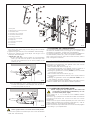
6) Mount the brackets on the transmission shafts and fasten
them to the door panel using screws, taking care to maintain
perfect alignment.
7) Tighten the grub screws on the transmission shaft bushings.
8) Open the garage door and adjust the length of the
telescopic arms as follows:
• straight arms (fig. 12)
Cut the outer profile at the position of the transmission
shaft. (A). Push the inner profile of the telescopic arm
into the outer profile and cut off at the position of the
rotation pin. (B).
• curved arms (fig. 13)
Place the telescopic arm in position as shown in figure 13.
Cut the outer profile of the telescopic arm at point A.
Cut the inner profile at point B.
Leave a gap of about 1 cm at the ends of both profiles.
9) Fit the inner profile of the telescopic arm to the transmission
shaft and weld securely.
4.5. ADJUSTING THE COUNTERWEIGHTS
On completing mechanical installation, check whether the door
has become unbalanced by the weight of the operator and
accessories. If necessary, change the counterweights.
For optimum balancing, the door should remain in equilibrium in
an intermediate position (45°) with the operator released.
Also check that the door opens and closes smoothly without
jerky or irregular movements.
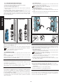
5. MOUNTING GEARED MOTOR UNIT
Depending on requirements, the geared motor unit can be
mounted in two different ways:
•With the drive shaft at the top (fig. 14)
The card support is fixed to the geared motor by means of 4
bolts which engage with nuts inserted in the guides.
Fastening the gearmotor in this way enables you to next install
the encoder (optional).
•With the drive shaft at the bottom (fig. 15)
The card support is fixed to the electric motor cap by means of
4 screws.
Fastening the gearmotor in this way does not enable you to
next install the encoder (optional).
The cover is designed for both applications (note that in the two
cases the release device is located in different positions).
6. START-UP
6.1. CONNECTING ELECTRONIC CARD
Before carrying out any operation on the control unit
(connections, programming, maintenance), be sure
to switch off the power supply.
Follow points 10, 11, 12, 13 and 14 of the GENERAL SAFETY
OBLIGATIONS.
As shown in fig.3, prepare the conduits and make the electrical
connections between the control unit and the chosen
accessories.
Always route the power cables separately from the control and
safety cables (pushbuttons, receivers, photocells, etc.). Use se-
parate sheaths to avoid electrical disturbance.
Follow the instructions provided with the control unit and program
it according to your requirements.
1etalpkcaB
2tekcarbgnitnuommracipocseleT
3tfahsnoissimsnarT
4)lanoitpo(machctiwstimiL
5tekcarbtfahsnoissimsnar
T
6wercsburggniruceS
7eliforpretuomrathgiartS
8mrathgiartS
9eliforpretuomradevruC
01mradevruC
11yekesaeleR
FIG.11
F
IG.12
F
IG.13

10
ENGLISH
B
A
OK ENCODER NO ENCODER
6.2. CHECKING DIRECTION OF ROTATION
1) Turn off the power supply to the system.
2) Move the door manually to its half open position.
3) Lock the operator (see section 9)
4) Turn the power supply back on.
5) Send an open signal (START) and check that this causes the
door to open.
If the door closes, invert the electric motor phase wires on the
card terminal block (brown and black wires).
In the double operator installation, connect the same colour
wires to the COM, OP and CL terminals on the control card and
the courtesy light card. If you have to invert the wires, invert
them on both motors.
6.3. ADJUSTMENT OF LIMIT SWITCHES (OPTIONAL)
Open the door as far as required, then turn the cam until it just
trips microswitch FCA (fig. 11).
Close the door, then turn the cam until it just trips microswitch
FCC (fig. 11).
If you are using a control unit with deceleration, advance
the activation of the microswitches.
Tighten the screws on the cams.
6.4. MOUNTING COVER
Fasten the cover in place by tightening the four screws at the
sides.
Push the 2 plastic caps onto the side slots on the cover not used
by the operator shaft.
Push the plastic cap onto the unused front slot on the cover for
gaining access to the release system.
7. TESTING THE AUTOMATION SYSTEM
Thoroughly test operation of the automation system and all
accessories connected to it.
Give the customer the page entitled ”User’s Guide” and
demonstrate how the automation system is used.
8. MANUAL OPERATION
The operator is equipped with an emergency release device
that can be operated from inside the garage. On request, a
lock can be fitted to the door panel to allow the release device
to be operated from outside.
If the door has to be operated manually due to a power failure
or a malfunction of the automation system, operate the release
device as follows:
- From inside (fig. 17)
Insert the hex wrench provided and turn clockwise about half
a turn until the stop is reached.
Depending on the type of installation, the release device
may be on the right (A) or left (B).
- From outside (fig. 18)
1) Open the safety door and insert the wrench.
2) Turn anticlockwise as far as possible and remove the lock
unit.
3) Insert the hex wrench provided and turn anticlockwise about
half a turn until the stop is reached.
9. RETURNING TO NORMAL OPERATION
To prevent an accidental movement from activating the door
during the operation, disconnect the power supply from the
system before locking the operator again.
- From inside (fig. 17)
Insert the hex wrench provided and turn anticlockwise about
half a turn until the stop is reached.
Depending on the type of installation, the release device
may be on the right (A) or left (B).
- From outside (fig. 18)
1) Insert the hex wrench provided and turn clockwise about
half a turn until the stop is reached.
2) Remove the hex wrench and insert the lock unit.
3) Turn the wrench clockwise so that it can be removed; close
the safety door again.
10. MAINTENANCE
Carry out the following operations at least every six months:
•Check that the motor torque is set correctly.
•Check the door’s rollers and sliding guides; clean and lubricate
if necessary.
•Check the efficiency of the release system.
•Check the efficiency of the safety devices.
11. REPAIRS
The end user has to be refrained to any tempted of repairing
end he mast contact only qualified Genius’ s personnel, or
Genius’s technical after sale offices.
FIG.15FIG.14
FIG.16
F
IG.17

Leggere attentamente le istruzioni prima di utilizzare il prodotto e conservarle
per eventuali necessità future.
NORME GENERALI DI SICUREZZA
Le automazioni EURO BREEZE 06, se correttamente installate ed utilizzate,
garantiscono un elevato grado di sicurezza.
Alcune semplici norme di comportamento possono evitare inoltre
inconvenienti accidentali:
- Non sostare assolutamente sotto la porta basculante.
- Non sostare e non permettere a bambini, persone o cose di sostare nelle
vicinanze dell’automazione, specialmente durante il funzionamento.
- Tenere fuori dalla portata dei bambini, radiocomandi o qualsiasi altro
datore d’impulso che possa azionare la porta.
- Non permettere ai bambini di giocare con l’automazione.
- Non contrastare volontariamente il movimento della porta.
- Evitare che rami o arbusti possano interferire col movimento della porta.
- Mantenere efficienti e ben visibili i sistemi di segnalazione luminosa.
- Non tentare di azionare manualmente la porta se non dopo averla
sbloccata.
- In caso di malfunzionamenti, sbloccare la porta per consentire l’accesso
ed attendere l’intervento tecnico di personale qualificato.
- Una volta predisposto il funzionamento manuale, prima di ripristinare il
funzionamento normale, togliere alimentazione elettrica all’impianto.
- Non eseguire alcuna modifica sui componenti facenti parte il sistema
d’automazione.
- L’utente utilizzatore deve astenersi da qualsiasi tentativo di riparazione
o d’intervento e deve rivolgersi solo ed esclusivamente a personale
qualificato GENIUS o centri d’assistenza GENIUS.
- Far verificare almeno semestralmente l’efficienza dell’automazione, dei
dispositivi di sicurezza e del collegamento di terra da personale quali-
ficato.
DESCRIZIONE
L'automazione EURO BREEZE 06 è ideale per automatizzare porte basculanti
a contrappesi di garages residenziali.
È costituita da un operatore elettromeccanico, un'apparecchiatura
elettronica di comando, una lampada di cortesia e un carter di protezione
integrati in un unico monoblocco da applicare al telo della basculante
con gli opportuni accessori.
Il sistema irreversibile garantisce il blocco meccanico della porta quando
il motore non è in funzione e quindi non occorre installare alcuna serratura;
uno sblocco manuale rende manovrabile la porta in caso di black-out
o disservizio.
La sicurezza antischiacciamento è garantita da un dispositivo elettronico
regolabile.
L'automazione EURO BREEZE 06 consente anche l'applicazione di due
operatori (EURO BREEZE 06 C + EURO BREEZE 06) sulla stessa porta.
La porta normalmente si trova chiusa; quando la centralina elettronica
riceve un comando di apertura tramite il radiocomando o qualsiasi altro
datore di impulso, aziona il motore elettrico ottenendo la rotazione della
porta fino alla posizione di apertura che consente l’accesso.
Se è stato impostato il funzionamento automatico, la porta si richiude da
sola dopo il tempo di pausa selezionato.
Se è stato impostato il funzionamento semiautomatico, è necessario
inviare un secondo impulso per ottenere la richiusura.
Un impulso di apertura dato durante la fase di apertura, provoca sempre
l’arresto del movimento.
Un impulso di apertura dato durante la fase di richiusura, provoca
l’inversione del movimento.
Un impulso di stop (se previsto) arresta sempre il movimento.
Per il dettagliato comportamento della porta nelle diverse logiche di
funzionamento, fare riferimento al Tecnico d’installazione.
Nelle automazioni possono essere presenti dispositivi di sicurezza
(fotocellule) che impediscono la richiusura della basculante quando un
ostacolo si trova nella zona da loro protetta.
Le automazioni EURO BREEZE 06 dispongono, di serie, di un dispositivo di
sicurezza antischiacciamento che limita la coppia trasmessa alla porta.
L’apertura manuale è possibile solo intervenendo sull’apposito sistema
di sblocco.
La segnalazione luminosa indica il movimento in atto della porta.
La luce di cortesia si attiva alla partenza del motore e permane per un
tempo di circa 90 secondi dal suo spegnimento.
FUNZIONAMENTO MANUALE
L'operatore EURO BREEZE 06 è dotato di uno sblocco d'emergenza
azionabile dall'interno; è possibile, a richiesta, applicare una serratura sul
telo che permette l'azionamento dello sblocco dall'esterno.
Nel caso sia necessario azionare manualmente la porta a causa di
mancanza di alimentazione elettrica o disservizio dell'automazione, è
necessario agire sul dispositivo di sblocco come segue:
- Dall'interno (fig. 1)
Inserire la chiave a brugola in dotazione e ruotare in senso orario di circa
mezzo giro fino all'arresto.
Attenzione: in base al tipo d'installazione, lo sblocco può trovarsi sul lato
destro (A) o sinistro (B).
- Dall'esterno (fig. 2)
1) Aprire lo sportellino di protezione ed inserire la chiave.
2) Ruotare in senso antiorario fino all'arresto ed estrarre il corpo serratura.
3) Inserire la chiave a brugola in dotazione e ruotare in senso antiorario
di circa mezzo giro fino all'arresto.
Guida per l'utente - End-user guide - Instructions pour l'utilisateur -
Instrucciones para el usuario - Benutzerinformation
EURO BREEZE 06
ITALIANO
Fig. 1
B
A
Fig. 2

Read the instructions carefully before using the product and keep for future
reference.
GENERAL SAFETY RULES
If correctly installed and operated, EURO BREEZE 06 automation systems
ensure a high level of safety.
However, some simple rules should be followed to avoid accidents:
- Do not stand underneath the garage door.
- Do not stand in the vicinity of the automation or allow anyone else,
especially children, to do so and do not place objects in the vicinity of
the automation. This is particularly important during operation.
- Keep remote controls and other control devices out of the reach of
children to prevent them from accidentally operating the door.
- Do not allow children to play with the automation.
- Do not deliberately obstruct the movement of the door.
- Make sure that branches or bushes do not interfere with the movement
of the door.
- Keep the luminous signalling systems efficient and clearly visible.
- Do not attempt to operate the door manually without first releasing it.
- In the event of a malfunction, release the gate to allow access and call
a qualified technician for service.
- After setting manual operation, disconnect the electricity supply from the
system before returning to normal operation.
- Do not make any modifications to components belonging to the
automation system.
- The end user has to be refrained to any tempted of repairing end he mast
contact only qualified Genius’ s personnel, or Genius’s technical after
sale offices.
- At least once every six months have the automation, the safety devices
and the earth connection checked by a qualified technician.
DESCRIPTION
The EURO BREEZE 06 automation system is ideal for operating residential
counterbalanced up-and-over garage doors.
It consists of an electromechanical operator, a control unit with courtesy
light and a protective cover integrated into a single unit to be mounted
on the garage door panel using the relevant accessories.
The irreversible system locks the door mechanically when the motor is not
running, so a lock is not required. A manual release device allows the door
to be operated in the case of a power failure or malfunction.
Anti-crushing safety is assured by an adjustable electronic device.
The EURO BREEZE 06 automation system allows two operators (EURO
BREEZE 06 C + EURO BREEZE 06) to be installed on the same door.
The door is normally closed. When the control unit receives an opening
signal via the radio control or another control device, it activates the
electric motor which rotates the door to the open position to allow access.
If automatic operation has been set, the door closes again after the
selected pause time.
If semiautomatic operation has been set, a second signal must be given
to close the door again.
Giving an opening signal while the door is opening always causes the door
to stop moving.
Giving an opening signal while the door is closing causes the door to
reverse its direction of movement.
A stop signal (if available) always stops the door.
Ask the installation engineer if you need further information on operation
of the door in the various operating logics.
The automation systems may include safety devices (photocells) which
prevent the door from closing when an obstacle lies within the area they
are protecting.
The EURO BREEZE 06 automation systems are provided as standard with
an anti-crushing safety device which limits the torque transmitted to the
door.
The door can be opened manually using the release system.
The light flashes to indicate that the gate is moving.
The courtesy light comes on when the motor starts and remains on for about
90 seconds after it has stopped.
MANUAL OPERATION
The EURO BREEZE 06 operator is equipped with an emergency release
device that can be operated from inside the garage. On request, a lock
can be fitted to the door panel to allow the release device to be operated
from outside.
If the door has to be operated manually due to a power failure or a
malfunction of the automation system, operate the release device as
follows:
- From inside (fig. 1)
Insert the hex wrench provided and turn clockwise about half a turn until
the stop is reached.
Warning: depending on the type of installation, the release device may
be on the right (A) or left (B).
- From outside (fig. 2)
1) Open the safety door and insert the wrench.
2) Turn anticlockwise as far as possible and remove the lock unit.
3) Insert the hex wrench provided and turn anticlockwise about half a turn
until the stop is reached.
RETURNING TO NORMAL OPERATION
To prevent an accidental movement from activating the door during the
operation, disconnect the power supply from the system before locking
the operator again.
- From inside (fig. 1)
Insert the hex wrench provided and turn anticlockwise about half a turn
until the stop is reached.
Warning: depending on the type of installation, the release device may
be on the right (A) or left (B).
- From outside (fig. 2)
1) Insert the hex wrench provided and turn clockwise about half a turn until
the stop is reached.
2) Remove the hex wrench and insert the lock unit.
3) Turn the wrench clockwise so that it can be removed; close the safety
door again.
ENGLISH
FRANÇAIS
Lire attentivement les instructions avant d’utiliser le produit et conserver la
notice d’instructions pour toute consultation future.
CONSIGNES DE SECURITE
Les automatismes EURO BREEZE 06, si correctement installés et utilisés,
garantissent un haut degré de sécurité.
L’observation des simples règles de comportement suivantes permettra
d’éviter de fâcheux inconvénients:
- Ne pas stationner sous la porte basculante.
- Ne pas stationner et empêcher quiconque de stationner à proximité de
l’automatisme, notamment pendant son fonctionnement. Ne pas laisser
traîner d’objets sous la porte basculante.
- Tenir à l’écart des enfants toutes radiocommandes ou n’importe quel
autre générateur d’impulsions, afin d’éviter toute manoeuvre accidentelle
de la porte.
- Empêcher les enfants de jouer avec l’automatisme.
- Ne pas arrêter volontairement le mouvement de la porte basculante.
- Eviter que des branches ou arbustes puissent interférer avec le mouvement
de la porte basculante.
- Toujours maintenir propres, efficaces et visibles les systèmes de signalisation
lumineuse.
- Ne pas tenter d’actionner manuellement la porte se ce n’est qu’après
son déverrouillage.
- En cas de mauvais fonctionnement, déverrouiller la porte basculante
pour permettre l’accès et attendre l’intervention d’un technicien spécialisé.
- Une fois le fonctionnement manuel prédisposé, séparer l’installation de
sa source d’alimentation en énergie électrique avant de rétablir le
fonctionnement normal.
- Ne pas procéder à des modifications des composants du système de
motorisation.
- Ne pas chercher à réparer ou à intervenir sur le produit. L’utilisateur doit
faire appel uniquement aux techniciens Genius ou au centre d’assistance
technique Genius.
- Faire vérifier semestriellement au moins l’efficacité de l’automatisme, des
dispositifs de sécurité et de la mise à la terre par un personnel qualifié.
RIPRISTINO DEL FUNZIONAMENTO NORMALE
Per evitare che un impulso involontario possa azionare la porta durante
la manovra, prima di ribloccare l'operatore togliere alimentazione
all'impianto.
- Dall'interno (fig. 1)
Inserire la chiave a brugola in dotazione e ruotare in senso antiorario di
circa mezzo giro fino all'arresto.
Attenzione: in base al tipo d'installazione, lo sblocco può trovarsi sul lato
destro (A) o sinistro (B).
- Dall'esterno (fig. 2)
1) Inserire la chiave a brugola in dotazione e ruotare in senso orario di circa
mezzo giro fino all'arresto.
2) Estrarre la chiave a brugola ed inserire il corpo serratura.
3) Ruotare la chiave in senso orario fino a quando è possibile estrarla;
richiudere lo sportellino di protezione.

DESCRIPTION
L’automatisme EURO BREEZE 06 constitue la solution idéale pour la
motorisation de portes basculantes à contrepoids et destinées à équiper
des garages de particuliers.
L’automatisme EURO BREEZE 06 est un monobloc composé d’un opérateur
électromécanique, d’une armoire de manoeuvre électronique avec
lampe de courtoisie et d’un carter, ou capot, protecteur à monter sur le
tablier de la porte à l’aide d’accessoires.
Le système irréversible garantit le verrouillage de la porte lorsque le moteur
est arrêté ne nécessitant pas l’installation d’une serrure; Un dispositif de
déverrouillage manuel permet de manoeuvrer la porte en cas de panne
de courant ou de défaillance du système.
La sécurité anti-écrasement est assurée par un dispositif électronique
réglable.
L’automatisme EURO BREEZE 06 permet aussi le montage de deux
opérateurs (EURO BREEZE 06 C + EURO BREEZE 06) sur la même porte.
La porte est normalement fermée; après la réception d’une commande
d’ouverture par une radiocommande ou n’importe quel autre générateur
d’impulsions, la centrale électronique actionne le moteur électrique qui
soulève la porte jusqu’en position horizontale pour permettre l’accès.
En cas de programmation du fonctionnement automatique, la porte
basculante se fermera après la temporisation sélectionnée.
En cas de programmation du fonctionnement semi-automatique, par
contre, il faudra délivrer une deuxième impulsion pour la fermeture de la
porte basculante.
Une impulsion d’ouverture délivrée pendant la phase d’ouverture
provoque toujours l’arrêt du mouvement de la porte basculante.
Une impulsion de stop délivrée pendant la phase de fermeture provoque
l’inversion du mouvement de la porte basculante.
Une impulsion de stop (s’il y en a un) arrête toujours le mouvement de la
porte basculante.
Pour le comportement détaillé de la porte basculante dans les différentes
logiques de fonctionnement, s’adresser à l’installateur.
Les automatismes peuvent être équipés de dispositifs, ou organes, de
sécurité (cellules photo-électriques) qui empêchent la fermeture de la
porte basculante en présence d’un obstacle dans leur champ de
surveillance. Les automatismes EURO BREEZE 06 disposent, de série, d’une
sécurité anti-écrasement qui permet de limiter la force transmise (couple)
à la porte basculante.
L’ouverture manuelle n’est donc possible qu’en manoeuvrant le système
de déverrouillage adéquat. La signalisation lumineuse indique l’ouverture
ou la fermeture de la porte basculante.
L’éclairage de courtoisie s’enclenche au démarrage du moteur et reste
allumé pendant environ 90 secondes après son arrêt.
FONCTIONNEMENT MANUEL
L’opérateur EURO BREEZE 06 comporte un dispositif de déverrouillage
manoeuvrable de l’intérieur; Sur demande, il est possible d’installer une
serrure sur le tablier pour permettre la manoeuvre du dispositif de
déverrouillage de l’extérieur.
Au cas où il faut manoeuvrer manuellement la porte basculante à la suite
d’une coupure de courant ou d’une défaillance de l’automatisme, agir
sur le dispositif de déverrouillage de la manière suivante:
- De l’intérieur (fig. 1)
Insérer la clé à six pans creux fournie et la tourner dans le sens des aiguilles
d’une montre d’un demi-tour environ, jusqu’à l’arrêt.
Attention: en fonction du type d’installation, le dispositif de déverrouillage
peut se situer sur le côté droit (A) ou gauche (B).
- De l’extérieur (fig. 2)
1) Ouvrir le petit couvercle de protection et insérer la clé.
2) Tourner la clé dans le sens inverse des aiguilles d’une montre et extraire
le corps de la serrure.
3) Insérer la clé à six pans creux fournie et la tourner dans le sens inverse
des aiguilles d’une montre d’un demi-tour environ, jusqu’à l’arrêt.
RÉTABLISSEMENT DU FONCTIONNEMENT NORMAL
Pour éviter qu’une impulsion involontaire puisse actionner la porte
basculante pendant la manoeuvre, il faut couper le courant au système
avant de rebloquer l’opérateur.
- De l’intérieur (fig. 1)
Insérer la clé à six pans creux fournie et la tourner dans le sens inverse des
aiguilles d’une montre d’un demi-tour environ, jusqu’à l’arrêt.
Attention: en fonction du type d’installation, le dispositif de déverrouillage
peut se situer sur le côté droit (A) ou gauche (B).
- De l’extérieur (fig. 2)
1) Insérer la clé à six pans creux fournie et la tourner dans le sens des
aiguilles d’une montre d’un demi-tour environ, jusqu’à l’arrêt.
2) Extraire la clé à six pans creux et insérer le corps de serrure.
3) Tourner la clé dans le sens des aiguilles d’une montre jusqu’à son
extraction; refermer le petit couvercle de protection.
ESPAÑOL
Lea detenidamente las instrucciones antes de iniciar la instalación del
equipo y consérvelas para consultas futuras.
ADVERTENCIAS GENERALES
Los mecanismos automáticos EURO BREEZE 06, cuando se instalan y
utilizan correctamente, garantizan un elevado nivel de seguridad.
Unas sencillas normas de actuación pueden evitar que se produzcan
accidentes:
- No permanecer, en ningún caso, bajo la puerta basculante.
- No pararse debajo ni permitir la detención de niños, personas o cosas
cerca del mecanismo automático, especialmente mientras está
funcionando.
- Mantener fuera del alcance de los niños los mandos a distancia y
cualquier emisor de impulsos capaz de accionar la puerta.
- No permitir que los niños jueguen con el automatismo.
- No oponer resistencia al movimiento de la puerta basculante.
- Evitar que ramas o arbustos puedan estorbar el movimiento de la
puerta.
- Mantener en buen estado y plena visibilidad los sistemas de señalización
luminosa.
- No tratar de accionar manualmente la puerta hasta no haberla
desbloqueada.
- En caso de fallo, desbloquear la puerta para permitir el acceso y solicitar
la intervención de personal técnico cualificado.
- Una vez reactivado el funcionamiento manual, antes de restablecer la
modalidad normal, desconectar la alimentación eléctrica de la
instalación.
- No efectuar ninguna modificación en los componentes del sistema
automático.
- El utilizador no tiene que intentar reparaciones o intervenciones y tiene
que contactar solamente personal encargado GENIUS o centros
autorizados GENIUS.
- Controlar cada seis meses, con la intervención de un técnico, la eficacia
del automatismo, de los dispositivos de seguridad y de la conexión a
tierra.
DESCRIPCIÓN
El mecanismo automático EURO BREEZE 06 es ideal para automatizar
puertas basculantes contrapesadas de los garajes comunitarios.
Está constituido por un actuador electromecánico, un equipo electrónico
de mando con lámpara de cortesía y una caja de protección, todo ello
integrado en un solo bloque que se aplica en la hoja de la puerta
basculante con los accesorios adecuados.
El sistema irreversible garantiza el bloqueo mecánico de la puerta cuando
el motor no está funcionando y, por lo tanto, no hace falta instalar
ninguna cerradura; un desbloqueo manual permite maniobrar la puerta
en el caso de que se corte la corriente o por fallo del sistema.
La seguridad antiaplastamiento está garantizada por un dispositivo
electrónico regulable.
El mecanismo de automatización EURO BREEZE 06 permite también la
aplicación de dos actuadores (EURO BREEZE 06 C + EURO BREEZE 06) en
la misma puerta.
La puerta está normalmente cerrada; cuando la centralita electrónica
recibe una orden de apertura mediante el radiomando o cualquier otro
emisor de impulsos, activa el motor eléctrico que hace rotar la puerta
hasta la posición de apertura que permite el acceso.
Si está programada para el funcionamiento automático, la puerta se
vuelve a cerrar sola tras el tiempo de pausa seleccionado.
Si está programado el funcionamiento semiautomático, hay que enviar
un segundo impulso para que se cierre.
Un impulso de apertura emitido durante la fase de apertura, provoca
siempre la detención del movimiento.
Un impulso de apertura emitido durante la fase de cierre, provoca la
inversión del movimiento.
Un impulso de stop (si lo hay) detiene siempre el movimiento.
Para informarse detalladamente del funcionamiento de la puerta en las
diferentes lógicas de funcionamiento, consultar al técnico instalador.
El mecanismo de automatización puede contar con dos dispositivos de
seguridad (células fotoeléctricas) que impiden que la puerta basculante
se vuelva a cerrar cuando hay un obstáculo en la zona que protegen.
Los mecanismos de automatización EURO BREEZE 06 están provistos, de
serie, de un dispositivo de seguridad antiaplastamiento que limita el par
transmitido a la puerta.
La apertura manual sólo se puede efectuar accionando el sistema de
desbloqueo.
La señalización luminosa indica que la puerta está en movimiento.
La luz de cortesía se activa con el arranque del motor y permanece
encendida alrededor de 90 segundos.

FUNCIONAMIENTO MANUAL
El actuador EURO BREEZE 06 está provisto de un desbloqueo de emergencia
accionable desde el interior; Sobre pedido, se puede poner una cerradura
en la puerta para accionar el desbloqueo desde el exterior.
En el caso de que se deba accionar manualmente la puerta a causa de
un corte de energía o de un fallo del actuador, se deberá utilizar el
dispositivo de desbloqueo tal como se indica:
- Desde el interior (fig. 1)
Introducir la llave Allen y girarla en sentido horario alrededor de medio
giro hasta que se pare.
Advertencia: según el tipo de instalación, el desbloqueo puede estar en
el lado derecho (A) o izquierdo (B).
- Desde el exterior (fig. 2)
1) Abrir la portezuela de protección e insertar la llave.
2) Girar en sentido antihorario hasta que se detenga y sacar el cuerpo
de la cerradura.
3) Insertar la llave Allen y girar en sentido antihorario alrededor de medio
giro hasta que se detenga.
REANUDACIÓN DEL FUNCIONAMIENTO NORMAL
Para evitar que un impulso involuntario pueda activar la puerta durante
la maniobra, cortar la corriente de la instalación antes de volver a
bloquear el actuador.
- Desde el interior (fig. 1)
Insertar la llave Allen y girarla en sentido antihorario alrededor de medio
giro hasta que se detenga.
Advertencia: según el tipo de instalación, el desbloqueo puede estar en
el lado derecho (A) o izquierdo (B).
- Desde el exterior (fig. 2)
1) Insertar la llave Allen y girar en sentido horario alrededor de medio giro
hasta que se detenga.
2) Sacar la llave Allen e insertar el cuerpo de la cerradura.
3) Girar la llave en sentido horario hasta que se pueda extraer; cerrar la
portezuela de protección.
Die Anleitungen vor Gebrauch des Produkts aufmerksam durchlesen und
für künftigen Bedarf aufbewahren.
ALLGEMEINE SICHERHEITSNORMEN
Bei fachgerechter Installation und korrektem Gebrauch gewährleistet die
Antriebsautomatik EURO BREEZE 06 einen hohen Sicherheitsgrad.
Durch die Beachtung einiger einfacher Verhaltensnormen können eventuelle
Gefahrensituationen weitgehend vermieden werden:
- Der Aufenthalt unter dem Kipptor ist streng verboten.
- Das Abstellen von Gegenständen und der Aufenthalt in unmittelbarer
Nähe der Antriebsautomatik ist nicht zulässig und Kindern oder anderen
Personen zu verbieten; dies ist insbesondere beim Bewegungsablauf des
Tors zu beachten.
- Fernbedienungen oder sonstige Impulsgeber, die eine Bewegung des
Tors auslösen können, sind außerhalb der Reichweite von Kindern
aufzubewahren.
- Kindern ist das Spielen mit der Antriebsautomatik zu verbieten.
- Den Bewegungsablauf des Kipptors nicht willkürlich behindern.
- Die Behinderung der Torbewegung durch Äste oder Büsche ist zu
vermeiden.
- Das Leuchtsignalsystem muß stets funktionstüchtig und gut sichtbar sein.
- Eine manuelle Betätigung des Tors darf erst nach der Entriegelung
erfolgen.
- Bei Betriebsstörungen das Kipptor zwecks Durchfahrt entriegeln und den
technischen Eingriff des qualifizierten Fachpersonals abwarten.
- Nach der Schaltung auf manuellen Betrieb ist die Anlage zur
Wiederaufnahme des normalen Betriebs zuvor von der Stromversorgung
zu trennen.
- Änderungen an Komponenten des Antriebssystems sind untersagt.
- Der Benutzer muss sich enthalten von jegliche Reparatur versuch oder
eingriff und muss sich anschließlich an qualifizierte GENIUS personal
wenden oder an autorisierte GENIUS Kundendienststellen.
- Die Funktionstüchtigkeit der Antriebsautomatik, Sicherheitsvorrichtungen
und Erdung ist mindestens alle sechs Monate durch technisches
Fachpersonal überprüfen zu lassen.
BESCHREIBUNG
Die Antriebsautomatik EURO BREEZE 06 ist für den Antrieb von
Gegengewicht-Kipptoren an Garagen von Einfamilienhäusern geeignet.
Das kompakte Gerät, das mit dem entsprechenden Zubehör auf dem
Torblatt angebracht wird, besteht aus einem elektromechanischen Antrieb,
einer elektronischen Steuereinheit, einer Service-Lampe und einem
Schutzgehäuse.
Das System ist selbsthemmend ausgeführt, so daß das Tor bei stehendem
Motor mechanisch verriegelt wird und sich die Installation von Schlössern
somit erübrigt; Für etwaige Stromausfälle oder Betriebsstörungen ist eine
manuelle Entriegelung vorgesehen.
Des weiteren ist das System mit einem einstellbaren elektronischen
Einklemmschutz-System ausgestattet.
Die Antriebsautomatik EURO BREEZE 06 ermöglicht auch den Einsatz zweier
Antriebe (EURO BREEZE 06 C + EURO BREEZE 06) an einem Tor.
Im Normalzustand ist das Tor geschlossen; bei Empfang eines
Öffnungssignals durch die Funksteuerung bzw. sonstige Impulsgeber
betätigt das elektronische Steuergerät den E-Motor und bewirkt somit eine
Tordrehung bis zur Öffnungsstellung, die eine Durchfahrt ermöglicht.
Im automatischen Betrieb schließt das Tor selbsttätig nach Ablauf der
gewählten Pausenzeit.
Im halbautomatischen Betrieb schließt das Tor dagegen erst nach Ausgabe
eines weiteren Schließsignals.
Ein während der Öffnungsphase erteilter Öffnungsimpuls bewirkt stets den
Stillstand der Bewegung.
Ein während der Schließphase erteilter Öffnungsimpuls bewirkt die
Umkehrung der Bewegung.
Ein Stoppimpuls (sofern vorgesehen) bewirkt stets den Stillstand der
Bewegung.
Über das genaue Verhalten des Tors in den einzelnen Betriebslogiken gibt
der Installateur gern Auskunft.
Mit den eventuell vorhandenen Sicherheitsvorrichtungen (Lichtschranken)
der Antriebe wird eine Torschließung bei Hindernissen im Wirkungsbereich
dieser Vorrichtungen verhindert.
Die Antriebe EURO BREEZE 06 ist serienmäßig mit einem Einklemmschutz-
System zur Begrenzung des Drehmoments an das Tor ausgerüstet.
Eine manuelle Öffnung ist nur anhand des entsprechenden
Entriegelungssystems möglich.
Die Leuchtsignale machen auf die Torbewegung aufmerksam.
Die Service-Lampe leuchtet beim Start des Motors auf und bleibt bis ca.
90 s nach Anhalten des Motors eingeschaltet.
MANUELLER BETRIEB
Der Antrieb EURO BREEZE 06 ist mit einer Notentriegelung versehen, welche
von der Innenseite betätigt werden kann; auf Anfrage kann ein Schloß auf
dem Torblatt zur Entriegelung von außen angebracht werden.
Sollte infolge von Stromausfällen bzw. Betriebsstörungen ein manueller
Torbetrieb erforderlich sein, muß wie folgt auf das Entriegelungssystem
zurückgegriffen werden:
- von innen (Abb. 1)
Inbusschlüssel aus dem Zubehör einsetzen und um ca. eine halbe Umdrehung
bis zum Anschlag nach rechts drehen.
Achtung: je nach Installationsart befindet sich die Entriegelung entweder
rechts (A) oder links (B).
- von außen (Abb. 2)
1) Schutzklappe öffnen und Schlüssel einsetzen.
2) Bis zum Anschlag nach links drehen und das Schloß entnehmen.
3) Inbusschlüssel aus dem Zubehör einsetzen und um ca. eine halbe
Umdrehung bis zum Anschlag nach links drehen.
WIEDERHERSTELLUNG DES NORMALEN BETRIEBS
Bevor der Antrieb wieder blockiert wird, ist die Stromzufuhr der Anlage zu
unterbrechen, damit jegliche Torbewegung durch einen irrtümlichen
Steuerimpuls vermieden wird.
- von innen (Abb. 1)
Inbusschlüssel aus dem Zubehör einsetzen und um ca. eine halbe Umdrehung
bis zum Anschlag nach links drehen.
Achtung: je nach Installationsart befindet sich die Entriegelung entweder
rechts (A) oder links (B).
- von außen (Abb. 2)
1) Inbusschlüssel aus dem Zubehör einsetzen und um ca. eine halbe
Umdrehung bis zum Anschlag nach rechts drehen.
2) Inbusschlüssel entnehmen und Schloß einsetzen.
3) Schlüssel nach rechts drehen, bis er entnommen werden kann;
Schutzklappe wieder schließen.
DEUTSCH

note - notes - note - notas - anmerkung - opmerkingen

GENIUS S.p.A.
Via Padre Elzi, 32
24050 - Grassobbio
BERGAMO-ITALY
tel. 0039.035.4242511
fax. 0039.035.4242600
www.geniusg.com
Le descrizioni e le illustrazioni del presente manuale non sono impegnative. GENIUS si riserva il diritto, lasciando inalterate le caratteristiche essenziali dell’apparecchiatura,
di apportare in qualunque momento e senza impegnarsi ad aggiornare la presente pubblicazione, le modifiche che essa ritiene convenienti per miglioramenti tecnici o
per qualsiasi altra esigenza di carattere costruttivo o commerciale.
The descriptions and illustrations contained in the present manual are not binding. GENIUS reserves the right, whils leaving the main features of the equipments unaltered, to
undertake any modifications to holds necessary for either technical or commercial reasons, at any time and without revising the present publication.
Les descriptions et les illustrations du présent manuel sont fournies à titre indicatif. GENIUS se réserve le droit d’apporter à tout moment les modifications qu’elle jugera utiles
sur ce produit tout en conservant les caractéristiques essentielles, sans devoir pour autant mettre à jour cette publication .
Las descripciones y las ilustraciones de este manual no comportan compromiso alguno. GENIUS se reserva el derecho, dejando inmutadas las características esenciales
de los aparatos, de aportar, en cualquier momento y sin comprometerse a poner al día la presente publicación, todas las modificaciones que considere oportunas para
el perfeccionamiento técnico o para cualquier otro tipo de exigencia de carácter constructivo o comercial.
Die Beschreibungen und Abbildungen in vorliegendem Handbuch sind unverbindlich. GENIUS behält sich das Recht vor, ohne die wesentlichen Eigenschaften dieses Gerätes
zu verändern und ohne Verbindlichkeiten in Bezung auf die Neufassung der vorliegenden Anleitungen, technisch bzw, konstruktiv / kommerziell bedingte Verbesserungen
vorzunehmen.
Timbro rivenditore: / Distributor’s stamp: / Timbre de l’agent: /
Sello del revendedor: / Fachhändlerstempel:
I0583 Rev.0
-
 1
1
-
 2
2
-
 3
3
-
 4
4
-
 5
5
-
 6
6
-
 7
7
-
 8
8
-
 9
9
-
 10
10
-
 11
11
-
 12
12
-
 13
13
-
 14
14


Genius Euro Breeze 06 Istruzioni per l'uso
- Tipo
- Istruzioni per l'uso
in altre lingue
Documenti correlati
-
Genius Euro Breeze 01 Istruzioni per l'uso
-
-
-
-
-
-
-
-
-