Pioneer XPRS102 Series 10 Inch Full Range Active Loudspeaker Guida utente
- Categoria
- Subwoofer
- Tipo
- Guida utente

简体中文Français Deutsch ItalianoEnglish Nederlands Español Português Русский
Quick start guide / Guide de démarrage rapide / Kurzanleitung / Guida di avvio
veloce/Snelstartgids/Guíadeiniciorápido/Guiadeiníciorápido/Краткое
руководствопользователя/快速入门指南
XPRS2 Series
XPRS102 / XPRS122 /
XPRS1152S / XPRS1182S
Active Loudspeaker / Haut-Parleur Actif / Aktivlautsprecher / Diffusore
Attivo/ActieveLuidspreker/AltavozActivo/Alto-FalanteAtivo/Активный
Громкоговоритель/有源扬声器
Active Subwoofer / Caisson De Basses Actif / Aktiv-Subwoofer / Subwoofer
Attivo / Actieve Subwoofer / Altavoz De Subgraves Activo / Subwoofer Ativo /
АктивныйСабвуфер/有源低音炮
pioneerdj.com/support/
For other support information for this product, visit the above site. / Pour en savoir plus à propos de ce produit,
consultez le site ci-dessus. / Weitere Support-Informationen zu diesem Produkt nden Sie auf der vorstehend
genannten Webseite. / Per altre informazioni relative all’assistenza per questo prodotto, visitare il sito indicato
sopra. / Bezoek de bovenstaande website voor meer informatie over ondersteuning voor dit product. / Para obtener
otra información de soporte para este producto, visite el sitio anterior. / Para obter outras informações sobre a
assistência a este produto, visite o site indicado acima. / Для получения прочей информации поддержки для
данного изделия посетите вышеуказанный сайт. / 如需了解有关本产品的其他支持信息,请访问上述网站。
保留备用
使用产品前请阅读使用说明

简体中文Français Deutsch Italiano
English
Nederlands Español Português Русский
2
En
How to read this manual
Thank you for choosing this speaker. To make sure you get the most from
its functions and use them effectively, please read the Instruction manual
and Precautions for Use carefully.
Please keep the Instruction manual and Precautions for Use together with
the Warranty.
Main features
2000-W high output and high sound quality are achieved by mounting
a D-class amplier module in a wooden cabinet featuring outstanding
acoustic characteristics. The XPRS2 can be used not only as a stationary
sound system in a stationary facility but also as sound equipment for
events as it can be easily transported and set up quickly.
• System type: Multi-purpose, active loudspeaker with DSP controls
• Transducer driver: 1-inch exit compression driver, 1.75-inch voice coil
• Subwoofer: ferrite woofer, 3-inch (76 mm) voice coil with long excursion
• Power rating: Class D 2000 W (peak)
• 4 DSP modes: LIVE/MUSIC/SPEECH/MONITOR
• Subwoofer: 80 Hz, 100 Hz, 120 Hz (NORMAL, BOOST, XTENDED)
• Electronic protections: Thermal/overload/digital limiter/compressor
• Power supply: 110 V – 240 V (50 Hz / 60 Hz)
• Enclosure construction: Plywood cabinet, black paint, rubber feet, metal
handle
• Mounting: One metal standard pole-mount, 10 x M10 threaded inserts
plus integrated pull-back cover
Rear panel
(full-range models)
INPUT
MIC/LINE
STEREO
HI-ZPOWER
HI-Z/LINE
SIGSIG
MIC
SIGSIG/LIMITER
OFF MAXOFF MAXOFF MAX
DIGITAL SIGNAL P ROCESSING
DSP
DISPLAY
MASTER
VO L
123
MIX OU T
2
e
5
d
c
b
a
9
8
3
4
1
6
7
1 AC INPUT
Connect the power cord to AC IN and then to the power outlet.
2 POWER
AC switch for turning the power on or off. When POWER is turned ON,
the POWER LED and the LCD screen both light up.
3 INPUT1
Level control for the LINE/MIC INPUT 1.
INPUT
Balanced input for sources such as mixing consoles, instruments, or
microphones. Connections can be made via a 1/4-inch TRS or XLR
connector.
4 INPUT2
Level control for the Hl-Z/LINE INPUT 2.
INPUT
Balanced input for sources such as mixing consoles, instruments, or
microphones. Connections can be made using a 1/4-inch TRS or XLR
connector.
5 STEREO LEVEL
Line input level control for STEREO.
6 INPUT LEVEL
Level control of the individual input.
7 Hl-Z signal light
When sound from a guitar is input, the system setting changes to Hl-Z
sensitivity and the signal light turns on.
8 MIC signal light
When sound from a microphone is input, the light turns on when the
system setting changes to MIC sensitivity.
9 SIG single channel signal light
When there is a signal, the signal light turns on.
a LCD
DSP control and monitoring interface.
b MASTER VOL
Total volume adjustment range: -60 dB – +10 dB.
DSP
Scroll through the menus and choose from the options. Press the
MASTER VOL knob to select an item on a menu.
c SIG/LIMITER signal light
Lights up green when there is a signal, and red when the amplifier starts
to compress.
d POWER indicators
Llights up when the speaker is turned on.
e MIX OUT
The XLR output sends mixed input signals to other speakers or
subwoofers. INPUT LEVEL controls the level of the signal sent to the
MIX OUT. The MASTER VOL or DSP control settings do not affect the
mixed output.

简体中文Français Deutsch Italiano
English
Nederlands Español Português Русский
3
En
Rear panel
(subwoofer model)
12
3
4
5
a
8
9
6
7
1 AC INPUT
The AC connection is established via the IEC connector. The IEC
connector is compatible with a lockout power cord (not included).
2 POWER
AC switch for turning the power on or off. When POWER is turned on,
the LED lights up.
3 LINK
The XLR output sends mixed input signals to other speakers or
subwoofers. VOLUME (input level) controls the level of signal sent to
LINK. The MASTER VOL and DSP control settings do not affect the
LINK signal.
4 INPUT LEFT (mono)/RIGHT
5 POWER indicators
The POWER LED lights up when the speaker is turned on.
6 SIG/LIMITER signal light
Lights up green when there is a signal, and red when the amplifier starts
to compress.
7 3DSP PRESET MODES
BOOST/EXTENDED LF/NORMAL
8 LPF
80 Hz/100 Hz/120 Hz
9 POLARITY
REVERSE/NORMAL
a VOLUME
Level control of an input signal.
Installation and connections
Important notes on installation
The sound produced by the speaker is subtly inuenced by the conditions
of the room you use it in. Carefully consider the installation location before
setting up the speaker to ensure the best possible conditions.
AlphaTheta Corporation will not be liable for any damages arising from use
of the speaker (including but not limited to loss of business opportunities),
regardless of the installation method used.
Be sure to use the handles on the top or the sides of the speaker when
moving and installing it.
CAUTION
To help proper cooling, please make sure enough space is kept between
each speaker and nearby walls or other components (minimum 30 cm
or more above, behind, and to the sides of each speaker). Leaving
insufcient space may cause the temperature inside the speaker to rise,
leading to malfunction or permanent damage.
Installation using a speaker pole
XPRS102/XPRS122
The full-range models of the XPRS2 Series have a 35-mm-diameter pole
socket on the bottom surface.
The subwoofer model of the XPRS2 Series have a 35-mm-diameter pole
socket on the top surface in which the pole can be secured rmly.
The combinations shown in the following diagrams are recommended for
the XPRS2 Series. Using a different combination may result in the speakers
toppling over and possibly causing damage or injury. To use a speaker pole,
check the cautions below and perform the installation safely.
CAUTION
• At least two people should lift each speaker together to install it. Be sure
to give enough consideration to safety when performing the work.
• Use a 35-mm-diameter speaker pole. Use a commercially-available
product with a length of 900 mm or less. AlphaTheta Corporation will not
be liable for any damages (including but not limited to loss of business
opportunities) arising from the use of a speaker pole other than the type
specified.
• Install the subwoofer in a stable location and secure the speaker pole
firmly.
• Ensure there is no danger of speakers toppling over.
• Cables should be taped or tied together with suitable tape or cable ties
to avoid the danger of tripping on the cables and causing the speakers to
topple over.
Pole socket
35-mm-diameter
pole socket
Pole socket
Front
Installation using a speaker pole
XPRS102, XPRS122
XPRS1152S, XPRS1182S

简体中文Français Deutsch Italiano
English
Nederlands Español Português Русский
4
En
Installation using the rigging points on the
speaker
• The full-range models have suspension-mounting rigging points on
them. The speaker can be suspended using commercially-available eye
bolts. The rigging point has an M10 screw hole (for an eye bolt with a
thread length of 30 mm – 50 mm).
• When installing the speaker suspended, ask a qualified technician to
perform the work.
• Remove the screws from the rigging points on the speaker and attach
eye bolts. Do not use the speaker while the screws are removed. The
sound will be adversely affected by air leakage.
• Be sure to use at least three rigging points to suspend the speaker.
Furthermore, be sure to also implement an extra safety measure such as
using a wire.
• Use brackets, wires, and a wall or ceiling strong enough to bear the
weight of the speaker. Ask for commercially-available brackets at the
shop where you purchased the speaker.
• Be sure to confirm the safety after installing the speaker and periodically
thereafter.
':Rigging points
Connections
Active subwoofer and active satellite speaker
CAUTION
Make your initial connections with all the equipment powered off and
ensure all the main volume controls are turned down completely.
1. Connect one end of a signal cable to the Output Left/Right on your
mixer and connect the other end of the cable to the Line Input on
the corresponding (left or right) active subwoofer.
2. Connect one end of another signal cable into the Link Left/Right or
Out Left/Right of the active subwoofer, and connect the other end
to the Line Input Left/Right of the active satellite speaker.
3. Connect the power cord to a mains supply.
4. Turn on your mixer first, then the active speakers.
5. Turn up the volume control of the active speakers.
6. Use the PFL function on the mixer to get the proper input level, and
adjust the Main Mix Level control to reach the desired output level.
7. When finished, turn off your active speakers first, then the mixer.
Line
Input
Pole
Main Out Left
Line In
Left/Mono
Subwoofer
DJ Mixer, Etc.
DJ Mixer, Etc.
INPUT
MIC/LINE
STEREO
HI-ZPOWER
HI-Z/LINE
SIGSIG
MIC
SIGSIG/LIMITER
OFF MAXOFF MAXOFF MAX
DIGITAL SIGNAL P ROCESSING
DSP
DISPLAY
MASTER
VO L
123
MIX OU T

简体中文Français Deutsch Italiano
English
Nederlands Español Português Русский
5
En
Specifications
Model XPRS102
System type Multi-purpose, 2-way active loudspeaker with
DSP controls
Transducer low 10” woofer, 2.5” voice coil
Transducer driver 1” exit compression driver, 1.75” voice coil
Frequency response
(-6 dB)
50 Hz – 20 kHz
Max SPL 129 dB
Power rating Class D 2000 W (peak)
4 DSP modes LIVE / MUSIC / SPEECH / MONITOR
Electronic protections Thermal / overload / digital Limiter / compressor
Connectors Input: MIC / LINE (Combo) / HI-Z / LINE
(Combo) / 3.5 mm STEREO MINI
Output: MIX (XLR)
Power supply 110 V – 240 V (50 Hz / 60 Hz)
Power consumption 800 W
Enclosure construction Plywood cabinet, black paint, rubber feet, metal
handle
Mounting One standard metal pole-mount. 10 x M10
threaded inserts plus integrated pull-back cover.
Dimensions (W x H x D) 11.77” (299 mm) x 20.5” (520 mm) x 12.2”
(310 mm)
Net weight 15.5 kg (34.2 lb)
Model XPRS122
System type Multi-purpose, 2-way active loudspeaker with
DSP controls
Transducer low 12” woofer, 3” voice coil
Transducer driver 1” exit compression driver, 1.75” voice coil
Frequency response
(-6 dB)
48 Hz – 20 kHz
Max SPL 131 dB
Power rating Class D 2000 W (peak)
4 DSP modes LIVE / MUSIC / SPEECH / MONITOR
Electronic Protections Thermal / overload / digital limiter / compressor
Connectors Input: MIC / LINE (Combo) / HI-Z / LINE
(Combo) / 3.5 mm STEREO MINI
Output: MIX (XLR)
Power supply 110 V – 240 V (50 Hz / 60 Hz)
Power consumption 800 W
Enclosure construction Plywood cabinet, black paint, rubber feet, metal
handle
Mounting One standard metal pole-mount. 10 x M10
threaded inserts plus integrated pull-back cover.
Dimensions (W x H x D) 14.28” (362.7 mm) x 25.07” (637 mm) x 13.78”
(350 mm)
Net weight 20.2 kg (44.6 lb)
Model XPRS1152S
System type 15” active vented subwoofer
Power rating Class D 4000 W (peak)
Transducer low 15” ferrite woofer, 3” (76 mm) voice coil with long
excursion
Frequency response
(-6 dB)
45 Hz – 120 Hz
Max.SPL 129 dB
DSP presets modes BOOST / XTENDED LF / NORMAL
Crossover frequency 80 Hz / 100 Hz / 120 Hz low pass lter
Electronic protections Over heat protection / short circuit protection /
digital compressor
Cooling Temperature-controlled fan
Connectors Input: Left Mono (Combo) / Right (Combo),
Output: Left Mono (XLR) / Right (XLR)
External controls Volume control / phase switch / switch for EQ
mode selector / switch for LPF / power on with
green LED / limiter with red LED
Power supply 100 V – 240 V (50 Hz / 60 Hz)
Power consumption 800 W
Enclosure construction Plywood cabinet, black paint, metal grille with
foam, rubber feet, double handles
Mounting One standard metal pole-mount.
Dimensions (W x H x D) 22.83” (580 mm) x 17.72” (450 mm) x 19.80”
(503 mm)
Net weight 26.3 kg (57.9 Ib)
Model XPRS1182S
System type 18” active vented subwoofer
Power rating Class D 4000 W (peak)
Transducer low 18” ferrite woofer, 3” (76 mm) voice coil with long
excursion
Frequency response
(-6 dB)
40 Hz – 120 Hz
Max.SPL 130 dB
DSP presets modes BOOST / XTENDED LF / NORMAL
Crossover frequency 80 Hz / 100 Hz / 120 Hz low pass lter
Electronic protections Over heat protection / short circuit protection /
digital compressor
Cooling Temperature-controlled fan
Connectors Input: Left Mono (Combo) / Right (XLR-F),
Output: Left Mono / Right (XLR-M)
External controls Volume control / phase switch / switch for EQ
mode selector / switch for LPF / power on with
green LED / limiter with red LED
Power supply 100 V – 240 V (50 Hz / 60 Hz)
Power consumption 800 W
Enclosure construction Plywood cabinet, black paint, metal grille with
foam, rubber feet, double handles
Mounting One standard metal pole-mount.
Dimensions (W x H x D) 26.02” (661 mm) x 21.06” (535 mm) x 21.12”
(536.5 mm)
Net weight 32.3 kg (71.2 Ib)
The specications and design of this product are subject to change without
notice.
© 2022 AlphaTheta Corporation. All rights reserved.

简体中文
Français
Deutsch ItalianoEnglish Nederlands Español Português Русский
6
Fr
Lecture de ce manuel
Merci d’avoir choisi cette enceinte. Pour être sûr(e) de l’utiliser
efcacement et de proter au mieux de ses fonctions, lisez attentivement
ce manuel d’utilisation et les précautions d’utilisation.
Conservez le manuel d’utilisation et les précautions d’utilisation avec la
garantie.
Principales caractéristiques
Une puissance de sortie élevée de 2000 W et une qualité sonore élevée
sont obtenues en montant un module d’amplication de classe D dans
une enceinte en bois aux caractéristiques acoustiques exceptionnelles. Le
XPRS2 peut être utilisé non seulement comme système de sonorisation
xe dans une installation xe, mais également comme équipement de
sonorisation pour des événements car il peut être facilement transporté et
installé rapidement.
• Type de système : enceinte active, polyvalente, avec contrôle du
processeur de signal numérique (DSP)
• Commande de transducteur : moteur à compression de sortie 1 pouce,
bobine acoustique 1,75 pouce
• Subwoofer : woofer en ferrite, bobine acoustique 3 pouces (76 mm) à
longue excursion
• Puissance nominale : Classe D 2000 W (crête)
• 4 modes DSP : LIVE/MUSIC/SPEECH/MONITOR
• Subwoofer : 80 Hz, 100 Hz, 120 Hz (NORMAL, BOOST, XTENDED)
• Protections électroniques : thermique/surcharge/limiteur numérique/
compresseur
• Alimentation électrique : 110 V – 240 V (50 Hz / 60 Hz)
• Boîtier : boîtier en contreplaqué, peint en noir, pieds en caoutchouc,
poignée en métal
• Fixation : une structure de xation du tube métallique standard,
10 inserts letés M10 plus cache rétractable
Panneau arrière
(modèles à gamme étendue)
INPUT
MIC/LINE
STEREO
HI-ZPOWER
HI-Z/LINE
SIGSIG
MIC
SIGSIG/LIMITER
OFF MAXOFF MAXOFF MAX
DIGITAL SIGNAL P ROCESSING
DSP
DISPLAY
MASTER
VO L
123
MIX OU T
2
e
5
d
c
b
a
9
8
3
4
1
6
7
1 AC INPUT
Branchez le cordon d’alimentation à l’entrée AC IN, puis à la prise de
courant.
2 POWER
Commutateur secteur de mise sous/hors tension. Lorsque le
commutateur POWER est réglé sur ON, la LED POWER et l’écran LCD
s’allument tous deux.
3 INPUT1
Contrôle de niveau de LINE/MIC INPUT 1.
INPUT
Entrée équilibrée pour des sources telles que des tables de mixage,
des instruments ou des microphones. Les branchements peuvent être
réalisés via un connecteur TRS ou XLR de 1/4 de pouce.
4 INPUT2
Contrôle de niveau de HI-Z/LINE INPUT 2.
INPUT
Entrée équilibrée pour des sources telles que des tables de mixage,
des instruments ou des microphones. Les branchements peuvent être
réalisés à l’aide d’un connecteur TRS ou XLR de 1/4 de pouce.
5 STEREO LEVEL
Contrôle de niveau de l’entrée ligne pour le paramètre STEREO.
6 INPUT LEVEL
Contrôle de niveau de l’entrée individuelle.
7 Voyant HI-Z
Lorsqu’un son de guitare est entré, les paramètres du système
basculent vers la sensibilité HI-Z et le voyant s’allume alors.
8 Voyant MIC
Lorsqu’un son de micro est entré, le voyant s’allume lorsque les
paramètres du système basculent vers la sensibilité MIC.
9 Voyant de canal unique SIG
En présence d’un signal, le voyant s’allume.
a LCD
Contrôle du DSP et interface de surveillance.
b MASTER VOL
Plage totale de réglage du volume : -60 dB – +10 dB.
DSP
Faites défiler les menus et sélectionnez les options souhaitées.
Appuyez sur le bouton MASTER VOL pour sélectionner un élément d’un
menu.
c Voyant SIG/LIMITER
S’allume en vert en cas de signal et en rouge si l’amplificateur
commence à compresser.
d Indicateur POWER
S’allume lorsque l’enceinte est activée.
e MIX OUT
La sortie XLR envoie des signaux d’entrée mélangés aux autres
enceintes ou subwoofers. INPUT LEVEL contrôle le niveau du signal
envoyé à MIX OUT. Les paramètres de contrôle de MASTER VOL ou
DSP n’affectent pas la sortie mélangée.

简体中文
Français
Deutsch ItalianoEnglish Nederlands Español Português Русский
7
Fr
Panneau arrière
(modèle de subwoofer)
12
3
4
5
a
8
9
6
7
1 AC INPUT
La connexion au secteur est établie via le connecteur IEC. Le
connecteur IEC est compatible avec un cordon d’alimentation de
verrouillage (non inclus).
2 POWER
Commutateur secteur de mise sous/hors tension. Lorsque POWER est
actionné, la LED s’allume.
3 LINK
La sortie XLR envoie des signaux d’entrée mélangés aux autres
enceintes ou subwoofers. VOLUME (niveau de l’entrée) contrôle
le niveau du signal envoyé à LINK. Les paramètres de contrôle de
MASTER VOL et DSP n’affectent pas le signal LINK.
4 INPUT LEFT (mono)/RIGHT
5 Indicateur POWER
La LED POWER s’allume lorsque l’enceinte est activée.
6 Voyant SIG/LIMITER
S’allume en vert en cas de signal et en rouge si l’amplificateur
commence à compresser.
7 3DSP PRESET MODES
BOOST/EXTENDED LF/NORMAL
8 LPF
80 Hz/100 Hz/120 Hz
9 POLARITY
REVERSE/NORMAL
a VOLUME
Contrôle de niveau d’un signal d’entrée.
Installation et branchements
Remarques importantes relatives à l’installation
Le son produit par l’enceinte est subtilement inuencé par les conditions
ambiantes de la pièce dans laquelle vous l’utilisez. Rééchissez bien au
lieu d’installation de l’enceinte avant de la congurer an de réunir les
meilleures conditions possibles.
AlphaTheta Corporation ne pourra être tenue responsable en cas de
dommage découlant de l’utilisation de l’enceinte (y compris, de manière
non exhaustive, la perte d’opportunités professionnelles), quelle que soit
la méthode d’installation appliquée.
Veillez à utiliser les poignées situées dans la partie supérieure ou sur les
côtés de l’enceinte lorsque vous la déplacez ou l’installez.
ATTENTION
An d’assurer un bon refroidissement, prévoyez sufsamment d’espace
entre chaque enceinte et entre une enceinte et les murs environnants ou
d’autres composants proches (au moins 30 cm au-dessus, derrière et sur
les côtés de chaque enceinte). Si vous ne laissez pas un espace sufsant,
la température à l’intérieur de l’enceinte risque d’augmenter, entraînant
des dysfonctionnements ou des dommages permanents.
Installation à l’aide d’un tube d’enceinte
XPRS102/XPRS122
Les modèles à gamme étendue de la série XPRS2 sont équipés d’un
raccord pour tube de 35 mm de diamètre sur leur surface supérieure.
Le modèle subwoofer de la série XPRS2 dispose d’un raccord pour tube
de 35 mm de diamètre sur sa surface supérieure, dans lequel le tube peut
être xé en toute sécurité.
Les combinaisons représentées dans les schémas suivants sont
recommandées pour la série XPRS2. Une autre combinaison pourrait
causer le basculement des enceintes et potentiellement blesser quelqu’un
ou endommager du matériel. Pour utiliser un tube d’enceinte, respectez les
précautions ci-dessous et procédez à l’installation de manière sécurisée.
ATTENTION
• Au moins deux personnes doivent soulever ensemble chaque enceinte
afin de l’installer. Accordez suffisamment d’attention aux principes de
sécurité lorsque vous procédez à l’installation.
• Utilisez un tube d’enceinte de 35 mm de diamètre. Utilisez un produit
disponible dans le commerce, d’une longueur maximale de 900 mm.
AlphaTheta Corporation ne pourra être tenue responsable en cas de
dommage (y compris, de manière non exhaustive, la perte d’opportunités
professionnelles) découlant de l’utilisation d’un tube d’enceinte autre que
le type spécifié.
• Installez le subwoofer à un endroit stable et fixez correctement le tube
d’enceinte.
• Assurez-vous que les enceintes ne risquent pas de basculer.
• Les câbles doivent être attachés ou maintenus par du ruban adhésif ou
des colliers de serrage appropriés afin d’éviter tout risque de trébucher
sur les câbles et de faire basculer les enceintes.
Raccord pour tube
Raccord pour tube de
35 mm de diamètre
Raccord pour tube
Avant
Installation à l’aide d’un tube d’enceinte
XPRS102, XPRS122
XPRS1152S, XPRS1182S

简体中文
Français
Deutsch ItalianoEnglish Nederlands Español Português Русский
8
Fr
Installation avec les points de fixation sur le
haut-parleur
• Les modèles large bande comportent des points de fixation de montage
suspendu. Le haut-parleur peut être suspendu à l’aide de boulons à œil
disponibles dans le commerce. Le point de fixation est doté d’un trou
de vis M10 (pour un boulon à œil d’une longueur de filetage de 30 mm
– 50 mm).
• Lors de l’installation du haut-parleur suspendu, demandez à un
technicien qualifié de procéder à l’opération.
• Retirez les vis des points de fixation sur le haut-parleur et fixez les
boulons à œil. N’utilisez pas le haut-parleur lorsque les vis sont retirées.
Les fuites d’air auraient une incidence négative sur le son.
• Veillez à utiliser au moins trois points de fixation pour suspendre le haut-
parleur. De plus, assurez-vous également de prendre une mesure de
sécurité supplémentaire telle que l’utilisation d’un fil.
• Utilisez des crochets, fils et un mur ou un plafond suffisamment résistant
pour supporter le poids du haut-parleur. Dans le magasin où vous avez
acheté le haut-parleur, demandez des crochets disponibles dans le
commerce.
• Assurez-vous de la sécurité après l’installation du haut-parleur et
régulièrement par la suite.
':Points de xation
Branchements
Subwoofer actif et enceinte satellite active
ATTENTION
Procédez aux branchements initiaux seulement si tous les
équipements sont éteints et veillez à ce que tous les principaux
réglages de volume soient totalement baissés.
1. Branchez l’une des extrémités du câble de signal à la sortie
gauche/droite de votre table de mixage et branchez l’autre
extrémité du câble à l’entrée ligne du subwoofer actif
correspondant (gauche ou droite).
2. Branchez l’extrémité d’un autre câble de signal à Lien gauche/
droite ou à la sortie gauche/droite du subwoofer actif et branchez
l’autre extrémité à l’entrée ligne gauche/droite de l’enceinte
satellite active.
3. Branchez le cordon d’alimentation au secteur.
4. Commencez par mettre en marche votre table de mixage, puis les
enceintes actives.
5. Utilisez le contrôle du volume des enceintes actives pour
augmenter le son.
6. Utilisez la fonction PFL de la table de mixage pour obtenir le niveau
d’entrée approprié et ajustez le réglage de niveau des sorties
principales pour mélange de manière à atteindre le niveau de
sortie souhaité.
7. Lorsque votre réglage est terminé, éteignez d’abord vos enceintes
actives, puis la table de mixage.
Entrée
ligne
Tube
Sortie principale
gauche
Entrée ligne
gauche/mono
Subwoofer
Table de mixage du DJ, etc.
Table de mixage du DJ, etc.
INPUT
MIC/LINE
STEREO
HI-ZPOWER
HI-Z/LINE
SIGSIG
MIC
SIGSIG/LIMITER
OFF MAXOFF MAXOFF MAX
DIGITAL SIGNAL P ROCESSING
DSP
DISPLAY
MASTER
VO L
123
MIX OU T

简体中文
Français
Deutsch ItalianoEnglish Nederlands Español Português Русский
9
Fr
Caractéristiques techniques
Modèle XPRS102
Type de système Enceinte active polyvalente 2 voies, avec
contrôles du DSP
Transducteur grave Woofer 10”, bobine acoustique 2,5”
Commande de
transducteur
Moteur à compression de sortie 1”, bobine
acoustique 1,75”
Réponse en fréquence
(-6 dB)
50 Hz – 20 kHz
Niveau de pression
acoustique (SPL)
maximale
129 dB
Puissance nominale Classe D 2000 W (crête)
4 modes DSP LIVE / MUSIC / SPEECH / MONITOR
Protections
électroniques
Thermique / surcharge / limiteur numérique /
compresseur
Connecteurs Entrée : MIC / LINE (Combo) / HI-Z / LINE
(Combo) / STEREO MINI de 3,5 mm
Sortie : MIX (XLR)
Alimentation électrique 110 V – 240 V (50 Hz / 60 Hz)
Puissance absorbée 800 W
Boîtier Boîtier en contreplaqué, peint en noir, pieds en
caoutchouc, poignée en métal
Fixation Une structure de xation du tube métallique
standard. 10 inserts letés M10 plus cache
rétractable intégré.
Dimensions (L x H x P) 299 mm (11,77”) x 520 mm (20,5”) x 310 mm
(12,2”)
Poids net 15,5 kg (34,2 lb)
Modèle XPRS122
Type de système Enceinte active polyvalente 2 voies, avec
contrôles du DSP
Transducteur grave Woofer 12”, bobine acoustique 3”
Commande de
transducteur
Moteur à compression de sortie 1”, bobine
acoustique 1,75”
Réponse en fréquence
(-6 dB)
48 Hz – 20 kHz
Niveau de pression
acoustique (SPL)
maximale
131 dB
Puissance nominale Classe D 2000 W (crête)
4 modes DSP LIVE / MUSIC / SPEECH / MONITOR
Protections
électroniques
Thermique / surcharge / limiteur numérique /
compresseur
Connecteurs Entrée : MIC / LINE (Combo) / HI-Z / LINE
(Combo) / STEREO MINI de 3,5 mm
Sortie : MIX (XLR)
Alimentation électrique 110 V – 240 V (50 Hz / 60 Hz)
Puissance absorbée 800 W
Boîtier Boîtier en contreplaqué, peint en noir, pieds en
caoutchouc, poignée en métal
Fixation Une structure de xation du tube métallique
standard. 10 inserts letés M10 plus cache
rétractable intégré.
Dimensions (L x H x P) 362,7 mm (14,28”) x 637 mm (25,07”) x 350 mm
(13,78”)
Poids net 20,2 kg (44,6 lb)
Modèle XPRS1152S
Type de système Subwoofer actif 15” à évent
Puissance nominale Classe D 4000 W (crête)
Transducteur grave Woofer 15” en ferrite, bobine acoustique 3”
(76 mm) avec longue excursion
Réponse en fréquence
(-6 dB)
45 Hz – 120 Hz
Niveau de pression
acoustique (SPL)
maximale
129 dB
Modes DSP prédénis BOOST / XTENDED LF / NORMAL
Fréquence de coupure
(crossover)
80 Hz / 100 Hz / 120 Hz ltre passe-bas
Protections
électroniques
Protection contre la surchauffe / protection contre
les courts-circuits / compresseur numérique
Refroidissement Ventilateur régulé selon la température
Connecteurs Entrée : gauche mono (Combo) / droite (Combo),
sortie : gauche mono (XLR) / droite(XLR)
Contrôles externes Contrôle du volume / commutateur de phase
/ commutateur du sélecteur du mode EQ /
commutateur pour LPF / mise sous tension avec
LED verte / limiteur avec LED rouge
Alimentation électrique 100 V – 240 V (50 Hz / 60 Hz)
Puissance absorbée 800 W
Boîtier Boîtier en contreplaqué, peint en noir, grille
en métal avec mousse, pieds en caoutchouc,
double poignée
Fixation Une structure de xation du tube métallique
standard.
Dimensions (L x H x P) 580 mm (22,83”) x 450 mm (17,72”) x 503 mm
(19,80”)
Poids net 26,3 kg (57,9 lb)
Modèle XPRS1182S
Type de système Subwoofer actif 18” à évent
Puissance nominale Classe D 4000 W (crête)
Transducteur grave Woofer 18” en ferrite, bobine acoustique 3”
(76 mm) avec longue excursion
Réponse en fréquence
(-6 dB)
40 Hz – 120 Hz
Niveau de pression
acoustique (SPL)
maximale
130 dB
Modes DSP prédénis BOOST / XTENDED LF / NORMAL
Fréquence de coupure
(crossover)
80 Hz / 100 Hz / 120 Hz ltre passe-bas
Protections
électroniques
Protection contre la surchauffe / protection contre
les courts-circuits / compresseur numérique
Refroidissement Ventilateur régulé selon la température
Connecteurs Entrée : gauche mono (Combo) / droite (XLR-F),
sortie : gauche mono / droite (XLR-M)
Contrôles externes Contrôle du volume / commutateur de phase
/ commutateur du sélecteur du mode EQ /
commutateur pour LPF / mise sous tension avec
LED verte / limiteur avec LED rouge
Alimentation électrique 100 V – 240 V (50 Hz / 60 Hz)
Puissance absorbée 800 W
Boîtier Boîtier en contreplaqué, peint en noir, grille
en métal avec mousse, pieds en caoutchouc,
double poignée
Fixation Une structure de xation du tube métallique
standard.
Dimensions (L x H x P) 661 mm (26,02”) x 535 mm (21,06”) x 536,5 mm
(21,12”)
Poids net 32,3 kg (71,2 lb)
Les spécications et la conception de ce produit peuvent être modiées
sans préavis.
© 2022 AlphaTheta Corporation. Tous droits réservés.

简体中文Français
Deutsch
ItalianoEnglish Nederlands Español Português Русский
10
De
Hinweise zu dieser Anleitung
Vielen Dank, dass Sie sich für diesen Lautsprecher entschieden haben.
Bitte lesen Sie die Bedienungsanleitung und die Vorsichtshinweise zum
Gebrauch aufmerksam durch, damit Sie die Funktionen des Geräts
optimal nutzen und sie effektiv einsetzen können.
Bitte bewahren Sie die Bedienungsanleitung und die Vorsichtshinweise
zum Gebrauch zusammen mit der Garantie auf.
Hauptmerkmale
Die 2000 Watt starke Ausgangsleistung und die hohe Klangqualität werden
durch ein Klasse-D-Verstärkermodul erreicht, das in ein Gehäuse aus Holz
mit herausragenden akustischen Eigenschaften verbaut ist. Der XPRS2
kann nicht nur als stationäres Beschallungssystem in einer stehenden
Einrichtung verwendet werden, sondern auch als Sound-Anlage für
Events, da er einfach zu transportieren und schnell aufzubauen ist.
• Systemausführung: Mehrzweck-Aktivlautsprecher mit DSP-Steuerung
• Schallwandler-Treiber: 1 Zoll Exit-Kompressionstreiber,
1,75-Zoll-Schwingspule
• Subwoofer: Ferrit-Tieftöner, 3-Zoll (76 mm) Schwingspule mit langem
Überhang
• Leistungsklasse: Klasse D, 2000 W (Spitze)
• 4 DSP-Modi: LIVE/MUSIC/SPEECH/MONITOR
• Subwoofer: 80 Hz, 100 Hz, 120 Hz (NORMAL, BOOST, XTENDED)
• Elektronische Schutzvorrichtungen: Thermisch/Überlast/Digitaler
Limiter/Kompressor
• Stromversorgung: 110 V – 240 V (50 Hz / 60 Hz)
• Gehäuseaufbau: Gehäuse aus Sperrholz, schwarze Lackierung,
Gummifüße, Metallgriff
• Befestigung: Eine Standard-Stangenbefestigung aus Metall, 10 x M10-
Gewindeeinsätze sowie eine integrierte Pull-back-Abdeckung
Rückseite
(Vollbereichsmodelle)
INPUT
MIC/LINE
STEREO
HI-ZPOWER
HI-Z/LINE
SIGSIG
MIC
SIGSIG/LIMITER
OFF MAXOFF MAXOFF MAX
DIGITAL SIGNAL P ROCESSING
DSP
DISPLAY
MASTER
VO L
123
MIX OU T
2
e
5
d
c
b
a
9
8
3
4
1
6
7
1 AC INPUT
Schließen Sie das Netzkabel an AC IN und danach an die Steckdose an.
2 POWER
Mit diesem Stromschalter wird das Gerät ein- und ausgeschaltet. Wenn
POWER auf ON geschaltet wird, geht sowohl die POWER-LED als der
LCD-Bildschirm an.
3 INPUT1
Pegelsteuerung für LINE/MIC INPUT 1.
INPUT
Symmetrischer Eingang für Quellen wie z.B. Mischpulte, Instrumente
oder Mikrofone. Anschlüsse können mit 1/4-Zoll-Klinkensteckern oder
XLR-Steckern erfolgen.
4 INPUT2
Pegelsteuerung für HI-Z/LINE INPUT 2.
INPUT
Symmetrischer Eingang für Quellen wie z.B. Mischpulte, Instrumente
oder Mikrofone. Anschlüsse können mit 1/4-Zoll-Klinkensteckern oder
XLR-Steckern erfolgen.
5 STEREO LEVEL
Line-Eingangspegelsteuerung für STEREO.
6 INPUT LEVEL
Pegelsteuerung für einen einzelnen Eingang.
7 HI-Z Signalanzeige
Wenn das Tonsignal einer Gitarre eingeht, wechselt die
Systemeinstellung auf HI-Z-Sensitivität und die Signalanzeige leuchtet
auf.
8 MIC Signalanzeige
Wenn das Tonsignal von einem Mikrofon eingeht, leuchtet die
Signalanzeige auf, wenn die Systemeinstellung auf MIC-Sensitivität
wechselt.
9 SIG Einzelkanal-Signalanzeige
Wenn ein Signal anliegt, leuchtet diese Signalanzeige auf.
a LCD
DSP-Steuerung und Monitoring-Schnittstelle.
b MASTER VOL
Gesamter Lautstärke-Einstellungsbereich: -60 dB – +10 dB.
DSP
Scrollen Sie durch die Menüs und wählen Sie aus den Optionen aus.
Drücken Sie den MASTER VOL-Regler, um innerhalb eines Menüs
einen Menüpunkt auszuwählen.
c SIG/LIMITER Signalanzeige
Leuchtet grün auf, wenn ein Signal anliegt, und rot, wenn der Verstärker
mit der Komprimierung beginnt.
d POWER Anzeige
Leuchtet, wenn der Lautsprecher eingeschaltet ist.
e MIX OUT
Der XLR-Ausgang sendet gemischte Eingangssignale an andere
Lautsprecher oder Subwoofer. INPUT LEVEL steuert den Pegel des
Signals, das an MIX OUT gesendet wird. Die Einstellungen für MASTER
VOL oder die DSP-Steuerung beeinflussen nicht den gemischten
Ausgang.

简体中文Français
Deutsch
ItalianoEnglish Nederlands Español Português Русский
11
De
Rückseite
(Subwoofer-Modell)
12
3
4
5
a
8
9
6
7
1 AC INPUT
Die Stromzufuhr erfolgt über den IEC-Anschluss. Der IEC-Anschluss
ist auch geeignet für ein verriegelbares Lock-Netzkabel (nicht im
Lieferumfang enthalten).
2 POWER
Mit diesem Stromschalter wird das Gerät ein- und ausgeschaltet. Wenn
POWER eingeschaltet wird, leuchtet die LED auf.
3 LINK
Der XLR-Ausgang sendet gemischte Eingangssignale an andere
Lautsprecher oder Subwoofer. VOLUME (Eingangspegel) steuert den
Pegel des Signals, das an LINK gesendet wird. Die Einstellungen
für MASTER VOL und die DSP-Steuerung beeinflussen nicht das
LINK-Signal.
4 INPUT LEFT (Mono)/RIGHT
5 POWER Anzeige
Die POWER LED leuchtet, wenn der Lautsprecher eingeschaltet ist.
6 SIG/LIMITER Signalanzeige
Leuchtet grün auf, wenn ein Signal anliegt, und rot, wenn der Verstärker
mit der Komprimierung beginnt.
7 3DSP PRESET MODES
BOOST/EXTENDED LF/NORMAL
8 LPF
80 Hz/100 Hz/120 Hz
9 POLARITY
REVERSE/NORMAL
a VOLUME
Pegelsteuerung für ein Eingangssignal.
Installation und Anschlüsse
Wichtige Hinweise zur Installation
Der Klang, den der Lautsprecher abgibt, wird auch ein wenig durch die
Beschaffenheiten des Raumes beeinusst, in dem Sie ihn verwenden.
Überlegen Sie sich vor Installation gut, wo Sie den Lautsprecher aufstellen
möchten, um die bestmöglichen Konditionen zu realisieren.
Die AlphaTheta Corporation übernimmt keine Haftung für irgendwelche
Schäden, die aus der Verwendung des Lautsprechers entstehen (einschließlich
aber nicht beschränkt auf entgangene Geschäftsmöglichkeiten), unabhängig
von der verwendeten Installationsmethode.
Verwenden Sie immer die Griffe oben am Lautsprecher bzw. an den
Seiten, wenn Sie ihn bewegen und installieren.
VORSICHT
Stellen Sie sicher, dass zwischen jedem Lautsprecher und Wänden oder
anderen Komponenten in der Nähe ausreichend Platz bleibt (mindestens
30 cm hinter und über jedem Lautsprecher sowie zu beiden Seiten),
um eine angemessene Kühlung zu ermöglichen. Falls zu wenig Platz
vorhanden ist, kann das zu steigenden Temperaturen im Lautsprecher
führen, was Fehlfunktionen oder dauerhafte Schäden hervorrufen kann.
Installation mit Lautsprecherstange
XPRS102/XPRS122
Die Vollbereichsmodelle der XPRS2-Serie sind auf der Unterseite mit
einer Halterung für Stangen mit 35 mm Durchmesser ausgestattet.
Das Subwoofer-Modell der XPRS2-Serie ist auf der Oberseite mit einer
Halterung für Stangen mit 35 mm Durchmesser ausgestattet. Hier kann
die Stange sicher befestigt werden.
Wir empfehlen für die XPRS2-Serie die Kombinationen, die in den
folgenden Abbildungen dargestellt sind. Falls Sie eine andere Kombination
verwenden, kann das dazu führen, dass die Lautsprecher umfallen
und sie eventuell Schäden oder Verletzungen verursachen. Wenn Sie
eine Lautsprecherstange verwenden möchten, lesen Sie die folgenden
Vorsichtshinweise und führen Sie die Installation auf sichere Weise durch.
VORSICHT
• Mindestens zwei Personen sollten gemeinsam einen Lautsprecher
anheben, um ihn aufzustellen. Stellen Sie sicher, dass Sie bei Ihrer Arbeit
ausreichend auf Sicherheitsaspekte achten.
• Verwenden Sie eine Lautsprecherstange mit 35 mm Durchmesser.
Verwenden Sie ein handelsübliches Produkt mit einer Länge von
maximal 900 mm. Die AlphaTheta Corporation übernimmt keine Haftung
für irgendwelche Schäden, die aus der Verwendung einer anderen
Lautsprecherstange als der angegebenen entstehen (einschließlich aber
nicht beschränkt auf entgangene Geschäftsmöglichkeiten).
• Stellen Sie den Subwoofer an einer stabilen Stelle auf und befestigen Sie
die Stange fest daran.
• Stellen Sie sicher, dass die Lautsprecher nicht umkippen können.
• Kabel sollten mit geeignetem Klebeband oder Kabelbindern miteinander
verbunden werden, um die Gefahr verhindern, dass eine Person über die
Kabel stolpert und den Lautsprecher umstößt.
Stangenhalterung
Halterung für Stangen
mit 35 mm Durchmesser
Stangenhalterung
Vorderseite
Installation mit Lautsprecherstange
XPRS102, XPRS122
XPRS1152S, XPRS1182S

简体中文Français
Deutsch
ItalianoEnglish Nederlands Español Português Русский
12
De
Installation mit den Befestigungspunkten auf
dem Lautsprecher
• Die Vollbereichsmodelle sind mit Aufhängungspunkten ausgestattet. Die
Lautsprecher können mit handelsüblichen Ringschrauben aufgehängt
werden. Der Befestigungspunkt verfügt über ein M10-Schraubenloch (für
eine Ringschraube mit einer Gewindelänge von 30 mm – 50 mm).
• Um die Lautsprecher hängend zu installieren, müssen Sie einen
qualifizierten Techniker beauftragen.
• Entfernen Sie die Schrauben aus den Befestigungspunkten auf dem
Lautsprecher und bringen Sie die Ringschrauben an. Verwenden Sie den
Lautsprecher nicht mit entfernten Schrauben. Der Sound wird aufgrund
der Luftlöcher beeinträchtigt.
• Benutzen Sie mindestens drei Befestigungspunkte, um die Lautsprecher
aufzuhängen. Stellen Sie zudem sicher, dass eine zusätzliche
Sicherheitsmaßnahme, wie ein Draht, verwendet wird.
• Verwenden Sie ausreichend starke Halterungen und Drähte und
achten Sie darauf, dass die Wand oder Decke stark genug ist, um das
Gewicht der Lautsprecher zu tragen. Fragen Sie nach handelsüblichen
Halterungen in dem Geschäft, in dem Sie Ihre Lautsprecher bezogen
haben.
• Überprüfen Sie unbedingt die Sicherheit direkt nach der Installation der
Lautsprecher und auch regelmäßig danach.
':Befestigungspunkte
Anschlüsse
Aktiver Subwoofer und aktive
Satelliten-Lautsprecher
VORSICHT
Führen Sie die anfänglichen Anschlüsse aus, wenn alle Geräte
ausgeschaltet sind. Stellen Sie sicher, dass alle wichtigen
Lautstärkeregler komplett heruntergedreht sind.
1. Verbinden Sie ein Ende des Signalkabels mit dem Ausgang Links/
Rechts an Ihrem Mixer. Schließen Sie das andere Ende des Kabels
an den Line-Eingang des entsprechenden aktiven Subwoofers
(links oder rechts) an.
2. Verbinden Sie ein Ende eines weiteren Signalkabels mit Link
Links/Rechts oder mit Out Links/Rechts am aktiven Subwoofer.
Schließen Sie das andere Ende des Kabels an den Line-Eingang
Links/Rechts des aktiven Satelliten-Lautsprechers an.
3. Schließen Sie das Netzkabel an eine Steckdose an.
4. Schalten Sie zuerst Ihren Mixer an, danach die Aktivlautsprecher.
5. Drehen Sie den Lautstärkeregler der aktiven Lautsprecher auf.
6. Verwenden Sie die PFL-Funktion am Mixer, um den richtigen Input-
Pegel zu erhalten, und stellen Sie die Main Mix Pegelsteuerung ein,
um den gewünschten Ausgangspegel zu erreichen.
7. Wenn Sie fertig sind, schalten Sie zuerst Ihre Aktivlautsprecher
aus und danach den Mixer.
Line-
Eingang
Stange
Main Out Links
Line In Links/
Mono
Subwoofer
DJ Mixer etc.
DJ Mixer etc.
INPUT
MIC/LINE
STEREO
HI-ZPOWER
HI-Z/LINE
SIGSIG
MIC
SIGSIG/LIMITER
OFF MAXOFF MAXOFF MAX
DIGITAL SIGNAL P ROCESSING
DSP
DISPLAY
MASTER
VO L
123
MIX OU T

简体中文Français
Deutsch
ItalianoEnglish Nederlands Español Português Русский
13
De
Technische Daten
Modell XPRS102
Systemausführung Mehrzweck-2-Wege-Aktivlautsprecher mit DSP-
Steuerung
Schallwandler tief 10” Subwoofer, 2,5” Schwingspule
Schallwandler-Treiber 1” Exit-Kompressionstreiber, 1,75”
Schwingspule
Frequenzgang (-6 dB) 50 Hz – 20 kHz
SDP maximal 129 dB
Leistungsklasse Klasse D, 2000 W (Spitze)
4 DSP-Modi LIVE / MUSIC / SPEECH / MONITOR
Elektronische
Schutzvorrichtungen
Thermisch / Überlast / Digitaler Limiter /
Kompressor
Anschlüsse Eingang: MIC / LINE (Combo) / HI-Z / LINE
(Combo) / 3,5 mm STEREO MINI
Ausgang: MIX (XLR)
Stromversorgung 110 V – 240 V (50 Hz / 60 Hz)
Leistungsaufnahme 800 W
Gehäuseaufbau Gehäuse aus Sperrholz, schwarze Lackierung,
Gummifüße, Metallgriff
Befestigung Eine Halterung für eine Standard-Metallstange.
10 x M10-Gewindeeinsätze sowie integrierte
Pull-back-Abdeckung.
Abmessungen (B x H x
T)
299 mm (11,77”) x 520 mm (20,5”) x 310 mm
(12,2”)
Nettogewicht 15,5 kg (34,2 lb)
Modell XPRS122
Systemausführung Mehrzweck-2-Wege-Aktivlautsprecher mit DSP-
Steuerung
Schallwandler tief 12” Subwoofer, 3” Schwingspule
Schallwandler-Treiber 1” Exit-Kompressionstreiber, 1,75” Schwingspule
Frequenzgang (-6 dB) 48 Hz – 20 kHz
SDP maximal 131 dB
Leistungsklasse Klasse D, 2000 W (Spitze)
4 DSP-Modi LIVE / MUSIC / SPEECH / MONITOR
Elektronische
Schutzvorrichtungen
Thermisch / Überlast / Digitaler Limiter /
Kompressor
Anschlüsse Eingang: MIC / LINE (Combo) / HI-Z / LINE
(Combo) / 3,5 mm STEREO MINI
Ausgang: MIX (XLR)
Stromversorgung 110 V – 240 V (50 Hz / 60 Hz)
Leistungsaufnahme 800 W
Gehäuseaufbau Gehäuse aus Sperrholz, schwarze Lackierung,
Gummifüße, Metallgriff
Befestigung Eine Halterung für eine Standard-Metallstange.
10 x M10-Gewindeeinsätze sowie integrierte
Pull-back-Abdeckung.
Abmessungen (B x H x
T)
362,7 mm (14,28”) x 637 mm (25,07”) x 350 mm
(13,78”)
Nettogewicht 20,2 kg (44,6 lb)
Modell XPRS1152S
Systemausführung 15” aktiv belüfteter Subwoofer
Leistungsklasse Klasse D, 4000 W (Spitze)
Schallwandler tief 15” Ferrit-Tieftöner, 3” (76 mm) Schwingspule
mit langem Überhang
Frequenzgang (-6 dB) 45 Hz – 120 Hz
SDP maximal 129 dB
DSP Voreinstellungs-
Modi
BOOST / XTENDED LF / NORMAL
Crossover-Frequenz 80 Hz / 100 Hz / 120 Hz Low Pass Filter
Elektronische
Schutzvorrichtungen
Überhitzungsschutz / Kurzschlussschutz /
digitaler Kompressor
Kühlung Ventilator, durch Temperatur kontrolliert
Anschlüsse Eingang: Links Mono (Combo) / Rechts (Combo),
Ausgang: Links Mono (XLR) / Rechts (XLR)
Externe Steuerungen Lautstärkeregelung / Phasenschalter /
Wahlschalter für den EQ-Modus / LPF-Schalter
/ Stromversorgung mit grüner LED / Limiter mit
roter LED
Stromversorgung 100 V – 240 V (50 Hz / 60 Hz)
Leistungsaufnahme 800 W
Gehäuseaufbau Gehäuse aus Sperrholz, schwarze Lackierung,
Metallgitter mit Schaumstoff, Gummifüße,
Doppelgriffe
Befestigung Eine Halterung für eine Standard-Metallstange.
Abmessungen (B x H x
T)
580 mm (22,83”) x 450 mm (17,72”) x 503 mm
(19,80”)
Nettogewicht 26,3 kg (57,9 lb)
Modell XPRS1182S
Systemausführung 18” aktiv belüfteter Subwoofer
Leistungsklasse Klasse D, 4000 W (Spitze)
Schallwandler tief 18” Ferrit-Tieftöner, 3” (76 mm) Schwingspule
mit langem Überhang
Frequenzgang (-6 dB) 40 Hz – 120 Hz
SDP maximal 130 dB
DSP Voreinstellungs-
Modi
BOOST / XTENDED LF / NORMAL
Crossover-Frequenz 80 Hz / 100 Hz / 120 Hz Low Pass Filter
Elektronische
Schutzvorrichtungen
Überhitzungsschutz / Kurzschlussschutz /
digitaler Kompressor
Kühlung Ventilator, durch Temperatur kontrolliert
Anschlüsse Eingang: Links Mono (Combo) / Rechts (XLR-F),
Ausgang: Links Mono / Rechts (XLR-M)
Externe Steuerungen Lautstärkeregelung / Phasenschalter /
Wahlschalter für den EQ-Modus / LPF-Schalter
/ Stromversorgung mit grüner LED / Limiter mit
roter LED
Stromversorgung 100 V – 240 V (50 Hz / 60 Hz)
Leistungsaufnahme 800 W
Gehäuseaufbau Gehäuse aus Sperrholz, schwarze Lackierung,
Metallgitter mit Schaumstoff, Gummifüße,
Doppelgriffe
Befestigung Eine Halterung für eine Standard-Metallstange.
Abmessungen (B x H x
T)
661 mm (26,02”) x 535 mm (21,06”) x 536,5 mm
(21,12”)
Nettogewicht 32,3 kg (71,2 lb)
Die technischen Daten und das Design dieses Produkts können ohne
vorherige Ankündigung geändert werden.
© 2022 AlphaTheta Corporation. Alle Rechte vorbehalten.

简体中文Français Deutsch
Italiano
English Nederlands Español Português Русский
14
It
Come leggere questo manuale
Grazie per aver scelto questo diffusore. Per sfruttarne al meglio le funzioni
e utilizzarle in modo efcace, leggere attentamente il manuale di istruzioni
e le precauzioni per l'uso.
Conservare il manuale di istruzioni e le precauzioni per l'uso insieme alla
garanzia.
Caratteristiche principali
Grazie al modulo amplicatore di classe D montato in una cassa in legno
dalle caratteristiche acustiche eccezionali, è possibile ottenere un’elevata
potenza di 2000 W e un’alta qualità del suono. L’XPRS2 può essere
utilizzato non solo come sistema audio sso in una struttura permanente,
ma anche come apparecchiatura audio per eventi, in quanto può essere
facilmente trasportato e montato rapidamente.
• Tipo di sistema: diffusore attivo multiuso con controlli DSP
• Driver del trasduttore: driver a compressione di uscita da 1 pollice,
bobina mobile da 1,75 pollici
• Subwoofer: woofer in ferrite, bobina mobile da 3 pollici (76 mm) a lunga
escursione
• Classe di potenza: Classe D 2000 W (picco)
• 4 modalità DSP: LIVE/MUSIC/SPEECH/MONITOR
• Subwoofer: 80 Hz, 100 Hz, 120 Hz (NORMAL, BOOST, XTENDED)
• Protezioni elettroniche: termica/da sovraccarico/limitatore digitale/
compressore
• Alimentazione: 110 V – 240 V (50 Hz / 60 Hz)
• Struttura della cassa: Mobile in multistrato, vernice nera, piedini in
gomma, maniglia in metallo
• Montaggio: un supporto per asta standard in metallo, 10 inserti lettati
M10 con coperchio a strappo integrato
Pannello posteriore
(modelli full range)
INPUT
MIC/LINE
STEREO
HI-ZPOWER
HI-Z/LINE
SIGSIG
MIC
SIGSIG/LIMITER
OFF MAXOFF MAXOFF MAX
DIGITAL SIGNAL P ROCESSING
DSP
DISPLAY
MASTER
VO L
123
MIX OU T
2
e
5
d
c
b
a
9
8
3
4
1
6
7
1 AC INPUT
Collegare il cavo di alimentazione a AC IN e quindi alla presa elettrica.
2 POWER
Interruttore CA per l'accensione o lo spegnimento. Quando l'unità è
accesa, il LED POWER e lo schermo LCD si accendono.
3 INPUT1
Controllo del livello per LINE/MIC INPUT 1.
INPUT
Ingresso bilanciato per sorgenti come console di missaggio, strumenti
o microfoni. I collegamenti possono essere realizzati tramite un
connettore TRS o XLR da 1/4 di pollice.
4 INPUT2
Controllo del livello per HI-Z/LINE INPUT 2.
INPUT
Ingresso bilanciato per sorgenti come console di missaggio, strumenti
o microfoni. I collegamenti possono essere realizzati utilizzando un
connettore TRS o XLR da 1/4 di pollice.
5 STEREO LEVEL
Controllo del livello di ingresso di linea per STEREO.
6 INPUT LEVEL
Controllo del livello del singolo ingresso.
7 Spia di segnalazione HI-Z
Quando viene immesso l'audio di una chitarra, l'impostazione di sistema
passa alla sensibilità HI-Z e la spia di segnalazione si accende.
8 Spia di segnalazione MIC
Quando viene immesso l'audio di un microfono, la spia si accende
appena l'impostazione di sistema passa alla sensibilità MIC.
9 Spia di segnalazione monocanale SIG
In presenza di segnale, la spia di segnalazione si accende.
a LCD
Controllo DSP e interfaccia di monitoraggio.
b MASTER VOL
Intervallo di regolazione totale del volume: -60 dB – +10 dB.
DSP
Scorrere tra i menu e selezionare le opzioni. Premere la manopola
MASTER VOL per selezionare la voce di un menu.
c Spia di segnalazione SIG/LIMITER
Si accende in verde in presenza di un segnale e in rosso quando
l'amplificatore inizia la compressione.
d Indicatore POWER
Si accende quando il diffusore è acceso.
e MIX OUT
L'uscita XLR invia segnali di ingresso miscelati con altri diffusori o
subwoofer. INPUT LEVEL controlla il livello del segnale inviato a MIX
OUT. Le impostazioni di controllo MASTER VOL o DSP non influiscono
sull'uscita miscelata.

简体中文Français Deutsch
Italiano
English Nederlands Español Português Русский
15
It
Pannello posteriore
(modello subwoofer)
12
3
4
5
a
8
9
6
7
1 AC INPUT
Il collegamento CA viene realizzato tramite il connettore IEC. Il
connettore IEC è compatibile con un cavo di alimentazione con blocco
(non incluso).
2 POWER
Interruttore CA per l’accensione o lo spegnimento. Quando l’unità è
accesa, il LED si accende.
3 LINK
L’uscita XLR invia segnali di ingresso miscelati con altri diffusori o
subwoofer. VOLUME (livello di ingresso) controlla il livello del segnale
inviato a LINK. Le impostazioni di controllo MASTER VOL e DSP non
influiscono sul segnale LINK.
4 INPUT LEFT (mono)/RIGHT
5 Indicatore POWER
Il LED POWER si accende quando il diffusore è acceso.
6 Spia di segnalazione SIG/LIMITER
Si accende in verde in presenza di un segnale e in rosso quando
l’amplificatore inizia la compressione.
7 3DSP PRESET MODES
BOOST/EXTENDED LF/NORMAL
8 LPF
80 Hz/100 Hz/120 Hz
9 POLARITY
REVERSE/NORMAL
a VOLUME
Controllo del livello di un segnale di ingresso.
Installazione e collegamenti
Note importanti sull’installazione
Il suono prodotto dal diffusore è inuenzato leggermente dalle condizioni
dell’ambiente di utilizzo. Valutare attentamente il luogo di installazione
prima di installare il diffusore per garantire le migliori condizioni possibili.
AlphaTheta Corporation non è responsabile di eventuali danni causati dall’uso
del diffusore (compresa a titolo esemplicativo la perdita di opportunità
commerciali), indipendentemente dal metodo di installazione utilizzato.
Per spostare e installare il diffusore, utilizzare sempre le maniglie sulla
parte superiore o sui lati.
ATTENZIONE
Per un corretto raffreddamento, lasciare sempre uno spazio sufciente
tra ogni diffusore e le pareti vicine o altri componenti (almeno 30 cm
sul lato posteriore, superiore e ai lati di ogni diffusore). Se si lascia uno
spazio insufciente, la temperatura interna del diffusore può aumentare,
causando malfunzionamenti o danni permanenti.
Installazione di un’asta per diffusori
XPRS102/XPRS122
I modelli full range della serie XPRS2 dispongono di un attacco per asta di
diametro 35 mm sulla supercie inferiore.
Il modello subwoofer della serie XPRS2 dispone di un attacco per asta
di diametro 35 mm sulla supercie superiore che consente di ssare
saldamente l’asta.
Le combinazioni illustrate nei seguenti schemi sono consigliate per la serie
XPRS2. L’uso di una combinazione diversa può causare il ribaltamento dei
diffusori ed eventuali danni o infortuni. Per utilizzare un’asta per diffusori,
leggere le seguenti precauzioni ed eseguire l’installazione in sicurezza.
ATTENZIONE
• Per installare un diffusore, occorrono almeno due persone per sollevarlo.
Prestare attenzione alla sicurezza durante l’esecuzione dei lavori.
• Utilizzare un’asta per diffusori di diametro 35 mm. Utilizzare un
prodotto disponibile in commercio con una lunghezza massima di 900
mm. AlphaTheta Corporation non è responsabile di eventuali danni
(compresa a titolo esemplificativo la perdita di opportunità commerciali)
causati dall’uso di un’asta per diffusori diversa dal tipo specificato.
• Installare il subwoofer in un punto stabile e fissare saldamente l’asta per
diffusori.
• Controllare che non vi sia pericolo di ribaltamento dei diffusori.
• I cavi devono essere fissati con nastro adesivo o legati con nastro adesivo o
fascette per evitare di inciampare sui cavi e far ribaltare i diffusori.
Attacco per asta
Attacco per asta di
diametro 35 mm
Attacco per asta
Anteriore
Installazione di un’asta per diffusori
XPRS102, XPRS122
XPRS1152S, XPRS1182S

简体中文Français Deutsch
Italiano
English Nederlands Español Português Русский
16
It
Installazione utilizzando i punti di attacco dei
diffusori
• I modelli a gamma completa sono dotati di punti di attacco per
installazione al soffitto. I diffusori possono essere installati al soffitto
utilizzando bulloni ad occhiello disponibili in commercio. I punti di attacco
presentano fori per viti M10 (compatibili con bulloni ad occhiello di
lunghezza del filetto compresa tra 30 mm – 50 mm).
• Se i diffusori vengono installati al soffitto, richiedere a un tecnico
qualificato di svolgere il lavoro.
• Rimuovere le viti dai punti di attacco sui diffusori e applicare i bulloni ad
occhiello Non utilizzare il diffusore se le viti sono state rimosse. Il suono
viene influenzato negativamente da perdite d’aria.
• Assicurarsi che i diffusori siano installati al soffitto con almeno tre punti
di attacco. Applicare inoltre un’ulteriore misura di sicurezza, per esempio
utilizzando un cavo.
• Utilizzare staffe, cavi e pareti sufficientemente solide per sostenere il
peso dei diffusori. Richiedere le staffe più adatte al rivenditore presso il
quale sono stati acquistati i diffusori.
• Accertarsi di verificare la sicurezza dell’installazione dopo il montaggio e
a intervalli regolari.
':Punti di attacco
Collegamenti
Subwoofer attivo e diffusore satellite attivo
ATTENZIONE
Effettuare i collegamenti iniziali con tutte le apparecchiature spente e
vericarechetuttiivolumiprincipalisianocompletamenteabbassati.
1. Collegare un’estremità di un cavo di segnale a Uscita sinistra/
destra sul mixer e collegare l’altra estremità del cavo a Ingresso
linea sul subwoofer attivo corrispondente (sinistro o destro).
2. Collegare un’estremità di un altro cavo di segnale a Collegamento
sinistra/destra o Uscita sinistra/destra del subwoofer attivo e
collegare l’altra estremità a Ingresso linea sinistra/destra del
diffusore satellite attivo.
3. Collegare il cavo di alimentazione a una presa elettrica.
4. Accendere prima il mixer, quindi i diffusori attivi.
5. Alzare il volume dei diffusori attivi.
6. Utilizzare la funzione PFL sul mixer per regolare il livello di
ingresso corretto, quindi regolare il controllo Livello mix principale
per ottenere il livello di uscita desiderato.
7. Al termine, spegnere prima i diffusori attivi, quindi il mixer.
Ingresso
linea
Asta
Uscita principale
sinistra
Ingresso linea
sinistra/Mono
Subwoofer
Mixer DJ, ecc.
Mixer DJ, ecc.
INPUT
MIC/LINE
STEREO
HI-ZPOWER
HI-Z/LINE
SIGSIG
MIC
SIGSIG/LIMITER
OFF MAXOFF MAXOFF MAX
DIGITAL SIGNAL P ROCESSING
DSP
DISPLAY
MASTER
VO L
123
MIX OU T

简体中文Français Deutsch
Italiano
English Nederlands Español Português Русский
17
It
Specifiche
Modello XPRS102
Tipo di sistema Diffusore attivo multiuso a 2 vie con controlli
DSP
Trasduttore bassi Woofer da 10”, bobina mobile da 2,5”
Driver del trasduttore Driver a compressione di uscita da 1”, bobina
mobile da 1,75”
Risposta in frequenza
(-6 dB)
50 Hz – 20 kHz
SPL massimo 129 dB
Classe di potenza Classe D 2000 W (picco)
4 modalità DSP LIVE / MUSIC / SPEECH / MONITOR
Protezioni elettroniche Termica / da sovraccarico / limitatore digitale /
compressore
Connettori Ingresso: MIC / LINE (Combo) / HI-Z / LINE
(Combo) / STEREO MINI da 3,5 mm
Uscita: MIX (XLR)
Alimentazione 110 V – 240 V (50 Hz / 60 Hz)
Consumo di corrente 800 W
Struttura della cassa Mobile in multistrato, vernice nera, piedini in
gomma, maniglia in metallo
Montaggio Un supporto per asta standard in metallo.
10 inserti lettati M10 con coperchio a strappo
integrato.
Dimensioni (L x A x P) 299 mm (11,77”) x 520 mm (20,5”) x 310 mm
(12,2”)
Peso netto 15,5 kg (34,2 lb)
Modello XPRS122
Tipo di sistema Diffusore attivo multiuso a 2 vie con controlli
DSP
Trasduttore bassi Woofer da 12”, bobina mobile da 3”
Driver del trasduttore Driver a compressione di uscita da 1”, bobina
mobile da 1,75”
Risposta in frequenza
(-6 dB)
48 Hz – 20 kHz
SPL massimo 131 dB
Classe di potenza Classe D 2000 W (picco)
4 modalità DSP LIVE / MUSIC / SPEECH / MONITOR
Protezioni elettroniche Termica / da sovraccarico / limitatore digitale /
compressore
Connettori Ingresso: MIC / LINE (Combo) / HI-Z / LINE
(Combo) / STEREO MINI da 3,5 mm
Uscita: MIX (XLR)
Alimentazione 110 V – 240 V (50 Hz / 60 Hz)
Consumo di corrente 800 W
Struttura della cassa Mobile in multistrato, vernice nera, piedini in
gomma, maniglia in metallo
Montaggio Un supporto per asta standard in metallo.
10 inserti lettati M10 con coperchio a strappo
integrato.
Dimensioni (L x A x P) 362,7 mm (14,28”) x 637 mm (25,07”) x 350 mm
(13,78”)
Peso netto 20,2 kg (44,6 lb)
Modello XPRS1152S
Tipo di sistema Subwoofer attivo ventilato da 15”
Classe di potenza Classe D 4000 W (picco)
Trasduttore bassi Woofer in ferrite da 15”, bobina mobile da 3”
(76 mm) a lunga escursione
Risposta in frequenza
(-6 dB)
45 Hz – 120 Hz
SPL massimo 129 dB
Modalità DSP
predenite
BOOST / XTENDED LF / NORMAL
Frequenza di crossover Filtro passa basso da 80 Hz / 100 Hz / 120 Hz
Protezioni elettroniche Protezione da surriscaldamento / protezione da
cortocircuito / compressore digitale
Raffreddamento Ventola termostatica
Connettori Ingresso: mono sinistra (Combo) / destra
(Combo), Uscita: mono sinistra (XLR) / destra
(XLR)
Controlli esterni Controllo volume / commutazione fase /
interruttore selettore modalità EQ / interruttore
per LPF / accensione con LED verde / limitatore
con LED rosso
Alimentazione 100 V – 240 V (50 Hz / 60 Hz)
Consumo di corrente 800 W
Struttura della cassa Mobile in multistrato, vernice nera, griglia
metallica con schiuma, piedini in gomma, doppie
maniglie
Montaggio Un supporto per asta standard in metallo.
Dimensioni (L x A x P) 580 mm (22,83”) x 450 mm (17,72”) x 503 mm
(19,80”)
Peso netto 26,3 kg (57,9 lb)
Modello XPRS1182S
Tipo di sistema Subwoofer attivo ventilato da 18”
Classe di potenza Classe D 4000 W (picco)
Trasduttore bassi Woofer in ferrite da 18”, bobina mobile da 3”
(76 mm) a lunga escursione
Risposta in frequenza
(-6 dB)
40 Hz – 120 Hz
SPL massimo 130 dB
Modalità DSP
predenite
BOOST / XTENDED LF / NORMAL
Frequenza di crossover Filtro passa basso da 80 Hz / 100 Hz / 120 Hz
Protezioni elettroniche Protezione da surriscaldamento / protezione da
cortocircuito / compressore digitale
Raffreddamento Ventola termostatica
Connettori Ingresso: mono sinistra (Combo) / destra
(XLR-F), Uscita: mono sinistra / destra (XLR-M)
Controlli esterni Controllo volume / commutazione fase /
interruttore selettore modalità EQ / interruttore
per LPF / accensione con LED verde / limitatore
con LED rosso
Alimentazione 100 V – 240 V (50 Hz / 60 Hz)
Consumo di corrente 800 W
Struttura della cassa Mobile in multistrato, vernice nera, griglia
metallica con schiuma, piedini in gomma, doppie
maniglie
Montaggio Un supporto per asta standard in metallo.
Dimensioni (L x A x P) 661 mm (26,02”) x 535 mm (21,06”) x 536,5 mm
(21,12”)
Peso netto 32,3 kg (71,2 lb)
I dati tecnici e il design del prodotto sono soggetti a modiche senza
preavviso.
© 2022 AlphaTheta Corporation. Tutti i diritti riservati.

简体中文Français Deutsch ItalianoEnglish
Nederlands
Español Português Русский
18
Nl
Opmerkingen over deze
handleiding
Hartelijk dank voor uw keuze voor deze luidspreker. Lees de
instructiehandleiding en de voorzorgen voor het gebruik aandachtig zodat
u alle functies optimaal en effectief kunt gebruiken.
Bewaar de instructiehandleiding en de voorzorgen voor het gebruik samen
met de garantie.
Voornaamste kenmerken
De krachtige 2000W-uitgang en hoge geluidskwaliteit worden gerealiseerd
dankzij de constructie van een D-klasse versterkermodule in een houten
kast met uitstekende akoestische eigenschappen. De XPRS2 kan niet
alleen als een stationair geluidssysteem in een stationaire omgeving
worden gebruikt; het systeem kan gemakkelijk worden vervoerd en
opgesteld, en is dus ook geschikt als geluidsapparatuur voor evenementen.
• Type systeem: Actieve luidspreker voor meerdere doeleinden met
DSP-regelaars
• Transducerdriver: Compressiedriver met 1 inch-uitgang, 1,75
inch-spreekspoel
• Subwoofer: ferrietwoofer, 3 inch (76 mm)-spreekspoel met lange uitslag
• Nominaal vermogen: Klasse D 2000 W (piek)
• 4 DSP-modi: LIVE/MUSIC/SPEECH/MONITOR
• Subwoofer: 80 Hz, 100 Hz, 120 Hz (NORMAL, BOOST, XTENDED)
• Elektronische beveiligingen: Thermisch/overbelasting/digitale limiter/
compressor
• Voeding: 110 V – 240 V (50 Hz / 60 Hz)
• Constructie behuizing: Multiplex kast, zwarte verf, rubberen voetjes,
metalen greep
• Installatie: Eén metalen standaard paalstatief, 10 x M10 inzetstukken
met schroefdraad plus geïntegreerde terugklapbare afdekking
Achterpaneel (modellen met
volledig bereik)
INPUT
MIC/LINE
STEREO
HI-ZPOWER
HI-Z/LINE
SIGSIG
MIC
SIGSIG/LIMITER
OFF MAXOFF MAXOFF MAX
DIGITAL SIGNAL P ROCESSING
DSP
DISPLAY
MASTER
VO L
123
MIX OU T
2
e
5
d
c
b
a
9
8
3
4
1
6
7
1 AC INPUT
Sluit het netsnoer aan op AC IN en vervolgens op het stopcontact.
2 POWER
Netschakelaar om de voeding aan en uit te zetten. Als POWER
ingeschakeld is, branden het POWER-lampje en het lcd-scherm.
3 INPUT1
Niveauregelaar voor LINE/MIC INPUT 1.
INPUT
Gebalanceerde ingang voor bronnen zoals mengconsoles,
instrumenten of microfoons. Aansluitingen kunnen worden gemaakt via
een TRS- of XLR-connector van 1/4 inch.
4 INPUT2
Niveauregelaar voor HI-Z/LINE INPUT 2.
INPUT
Gebalanceerde ingang voor bronnen zoals mengconsoles,
instrumenten of microfoons. Aansluitingen worden gemaakt met behulp
van een TRS- of XLR-connector van 1/4 inch.
5 STEREO LEVEL
Line-ingangsniveauregelaar voor STEREO.
6 INPUT LEVEL
Niveauregelaar van de afzonderlijke ingang.
7 HI-Z-signaallampje
Als geluid van een gitaar wordt ingevoerd, gaat de systeeminstelling
over naar HI-Z-gevoeligheid en gaat het signaallampje aan.
8 MIC-signaallampje
Als geluid van een microfoon wordt ingevoerd, gaat het lampje aan
wanneer de systeeminstelling overgaat naar MIC-gevoeligheid.
9 SIG-signaallampje enkel kanaal
Het signaallampje gaat aan wanneer er een signaal is.
a LCD
DSP-regelaar en monitorinterface.
b MASTER VOL
Instelbereik voor totaal volume: -60 dB – +10 dB.
DSP
Hiermee kunt u door de menu's bladeren en opties kiezen. Druk op de
MASTER VOL-knop om een item in een menu te selecteren.
c SIG/LIMITER-signaallampje
Brandt groen wanneer er een signaal is, en rood wanneer de versterker
begint te comprimeren.
d POWER-indicatoren
Brandt wanneer de luidspreker ingeschakeld is.
e MIX OUT
De XLR-uitgang verstuurt gemengde ingangssignalen naar andere
luidsprekers of subwoofers. INPUT LEVEL regelt het niveau van
het signaal dat naar MIX OUT wordt verstuurd. De instelling van de
MASTER VOL- of DSP-regelaars heeft geen invloed op de gemengde
uitgang.

简体中文Français Deutsch ItalianoEnglish
Nederlands
Español Português Русский
19
Nl
Achterpaneel
(subwoofermodel)
12
3
4
5
a
8
9
6
7
1 AC INPUT
De netvoedingsaansluiting wordt via de IEC-connector gemaakt. De
IEC-connector is compatibel met een netsnoer met vergrendeling (niet
meegeleverd).
2 POWER
Netschakelaar om de voeding aan en uit te zetten. Als POWER
ingeschakeld is, brandt het led-lampje.
3 LINK
De XLR-uitgang verstuurt gemengde ingangssignalen naar andere
luidsprekers of subwoofers. VOLUME (ingangsniveau) regelt het
niveau van het signaal dat naar LINK wordt verzonden. De instelling
van de MASTER VOL- en DSP-regelaars heeft geen invloed op het
LINK-signaal.
4 INPUT LEFT (mono)/RIGHT
5 POWER-indicatoren
Het POWER-lampje brandt wanneer de luidspreker ingeschakeld is.
6 SIG/LIMITER-signaallampje
Brandt groen wanneer er een signaal is, en rood wanneer de versterker
begint te comprimeren.
7 3DSP PRESET MODES
BOOST/EXTENDED LF/NORMAL
8 LPF
80 Hz/100 Hz/120 Hz
9 POLARITY
REVERSE/NORMAL
a VOLUME
Niveauregelaar van een ingangssignaal.
Installatie en aansluitingen
Belangrijke opmerkingen over de installatie
Het geluid van de luidspreker wordt subtiel beïnvloed door de
omstandigheden in de ruimte waarin deze wordt gebruikt. Beoordeel de
installatieplaats zorgvuldig voordat u de luidspreker opstelt om voor de
best mogelijke omstandigheden te zorgen.
AlphaTheta Corporation zal niet aansprakelijk zijn voor enige schade die
voortkomt uit gebruik van de luidspreker (inclusief maar niet beperkt tot
verlies van zakelijke mogelijkheden), ongeacht de installatiewijze.
Gebruik bij verplaatsing en installatie de handgrepen bovenaan of aan de
zijkanten van de luidspreker.
VOORZICHTIG
Voor afdoende koeling moet u ervoor zorgen dat er voldoende ruimte blijft
tussen alle luidsprekers en de muren of andere componenten dicht bij (ten
minste 30 cm of meer boven, achter en rondom elke luidspreker). Als er
onvoldoende ruimte is, kan de temperatuur in de luidspreker oplopen, met
storingen of permanente beschadiging tot gevolg.
Installatie met een luidsprekerpaal
XPRS102/XPRS122
De modellen met volledig bereik van de XPRS2-reeks hebben een
aansluiting voor een paal met een diameter van 35 mm aan de onderkant.
Het subwoofermodel van de XPRS2-reeks heeft een aansluiting voor
een paal met een diameter van 35 mm aan de bovenkant waarin de paal
stevig kan worden vastgezet.
De combinaties die in de volgende afbeeldingen worden getoond,
worden aanbevolen voor de XPRS2-reeks. Het gebruik van een andere
combinatie kan ertoe leiden dat de luidspreker omvalt en mogelijk schade
of letsel veroorzaakt. Controleer voor gebruik van een luidsprekerpaal de
onderstaande waarschuwingen en voer de installatie veilig uit.
VOORZICHTIG
• Bij de installatie moet elke luidspreker door ten minste twee personen
samen worden opgetild. Besteed voldoende aandacht aan de veiligheid
bij het uitvoeren van het werk.
• Gebruik een luidsprekerpaal met een diameter van 35 mm. Gebruik een
in de handel verkrijgbaar product met een lengte van 900 mm of minder.
AlphaTheta Corporation zal niet aansprakelijk zijn voor schade (inclusief
maar niet beperkt tot verlies van zakelijke mogelijkheden) door het
gebruik van een andere luidsprekerpaal dan het gespecificeerde type.
• Installeer de subwoofer op een stabiele locatie en zet de luidsprekerpaal
stevig vast.
• Zorg ervoor dat er geen risico bestaat dat de luidspreker kan omvallen.
• De kabels moeten met geschikte tape of kabelbinders worden
samengebonden om het risico te voorkomen dat iemand over de kabels
struikelt en de luidspreker omver trekt.
Paalaansluiting
Aansluiting voor paal
met diameter van 35 mm
Paalaansluiting
Voorkant
Installatie met een luidsprekerpaal
XPRS102, XPRS122
XPRS1152S, XPRS1182S

简体中文Français Deutsch ItalianoEnglish
Nederlands
Español Português Русский
20
Nl
Installatie met de hijspunten op de luidspreker
• De modellen met volledig bereik zijn voorzien van hijspunten voor
hangmontage. De luidspreker kan opgehesen worden met in de handel
verkrijgbare oogbouten. Het hijspunt heeft een M10-schroefgat (voor een
oogbout met een draadlengte van 30 mm – 50 mm).
• Laat bij hangmontage van de luidspreker de installatie uitvoeren door
een erkende vakman.
• Verwijder de schroeven van de hijspunten op de luidspreker en bevestig
de oogbouten. Gebruik de luidspreker niet wanneer de schroeven niet
zijn aangebracht. Het geluid wordt negatief beïnvloed door luchtlekkage.
• Gebruik ten minste drie hijspunten om de luidspreker op te hangen.
Vraag naar in de handel verkrijgbare beugels in de winkel waar u de
luidspreker gekocht hebt.
• De gebruikte beugels, kabels en de muur of het plafond moeten sterk
genoeg zijn om het gewicht van de luidspreker te dragen. Vraag naar
in de handel verkrijgbare beugels in de winkel waar u de luidspreker
gekocht hebt.
• Controleer de veiligheid van de luidsprekerinstallatie na voltooiing van de
installatie en op regelmatige tijdstippen daarna.
':Ophangpunten
Verbindingen
Actieve subwoofer en actieve
satellietluidspreker
VOORZICHTIG
Maak de initiële aansluitingen met alle apparatuur uitgeschakeld en
zorg ervoor dat alle hoofdvolumeregelaars volledig omlaag gedraaid
zijn.
1. Sluit een uiteinde van een signaalkabel aan op de Uitgang links/
rechts van uw mengpaneel, en sluit het andere uiteinde van de
kabel aan op de Line-ingang op de overeenkomende (links of
rechts) actieve subwoofer.
2. Sluit een uiteinde van een andere signaalkabel aan op de Link
links/rechts of Uit links/rechts van de actieve subwoofer, en sluit
het andere uiteinde aan op de Line-ingang links/rechts van de
actieve satellietluidspreker.
3. Sluit het netsnoer op een netvoeding aan.
4. Zet eerst het mengpaneel aan en vervolgens de actieve
luidsprekers.
5. Draai de volumeregelaar van de actieve luidsprekers omhoog.
6. Gebruik de PFL-functie op het mengpaneel om het juiste
ingangsniveau te verkrijgen, en pas de hoofdmixniveauregelaar
aan om het gewenste uitgangsniveau te realiseren.
7. Wanneer u klaar bent, zet dan eerst de actieve luidsprekers uit, en
vervolgens het mengpaneel.
Line-ingang
Paal
Hoofduitgang links
Line in
links/mono
Subwoofer
DJ-mengpaneel, etc.
DJ-mengpaneel, etc.
INPUT
MIC/LINE
STEREO
HI-ZPOWER
HI-Z/LINE
SIGSIG
MIC
SIGSIG/LIMITER
OFF MAXOFF MAXOFF MAX
DIGITAL SIGNAL P ROCESSING
DSP
DISPLAY
MASTER
VO L
123
MIX OU T
La pagina si sta caricando...
La pagina si sta caricando...
La pagina si sta caricando...
La pagina si sta caricando...
La pagina si sta caricando...
La pagina si sta caricando...
La pagina si sta caricando...
La pagina si sta caricando...
La pagina si sta caricando...
La pagina si sta caricando...
La pagina si sta caricando...
La pagina si sta caricando...
La pagina si sta caricando...
La pagina si sta caricando...
La pagina si sta caricando...
La pagina si sta caricando...
La pagina si sta caricando...
La pagina si sta caricando...
La pagina si sta caricando...
La pagina si sta caricando...
-
 1
1
-
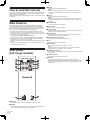 2
2
-
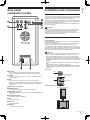 3
3
-
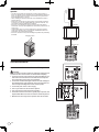 4
4
-
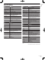 5
5
-
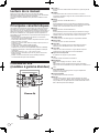 6
6
-
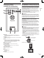 7
7
-
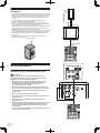 8
8
-
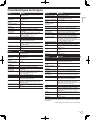 9
9
-
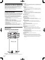 10
10
-
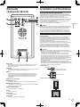 11
11
-
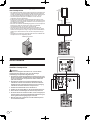 12
12
-
 13
13
-
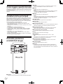 14
14
-
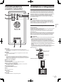 15
15
-
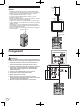 16
16
-
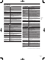 17
17
-
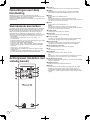 18
18
-
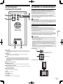 19
19
-
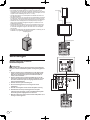 20
20
-
 21
21
-
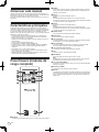 22
22
-
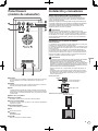 23
23
-
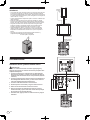 24
24
-
 25
25
-
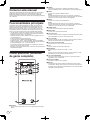 26
26
-
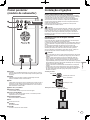 27
27
-
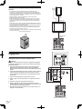 28
28
-
 29
29
-
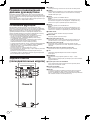 30
30
-
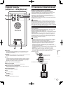 31
31
-
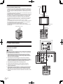 32
32
-
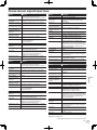 33
33
-
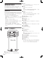 34
34
-
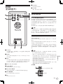 35
35
-
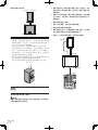 36
36
-
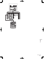 37
37
-
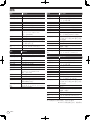 38
38
-
 39
39
-
 40
40


Pioneer XPRS102 Series 10 Inch Full Range Active Loudspeaker Guida utente
- Categoria
- Subwoofer
- Tipo
- Guida utente
in altre lingue
- français: Pioneer XPRS102 Series 10 Inch Full Range Active Loudspeaker Mode d'emploi
- español: Pioneer XPRS102 Series 10 Inch Full Range Active Loudspeaker Guía del usuario
- Nederlands: Pioneer XPRS102 Series 10 Inch Full Range Active Loudspeaker Gebruikershandleiding
- português: Pioneer XPRS102 Series 10 Inch Full Range Active Loudspeaker Guia de usuario