

ContentsContents
ContentsContents
Contents
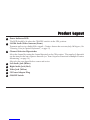
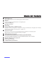
What You Get ............................................................................................................................................1
Product Layout ..........................................................................................................................................2
Setting Up ..................................................................................................................................................5
Setting Up-Camera ...................................................................................................................................6
Setting Up-Receiver ..................................................................................................................................9
Setting Up-Other Application ............................................................................................................... 12
Orienting Units for Optimal Performance ........................................................................................... 13
Auto-Sequence Function for Multiple Location Monitoring ............................................................ 14
Troubleshooting ...................................................................................................................................... 16
Care and Maintenance ........................................................................................................................... 17
Specifications ........................................................................................................................................... 18
Declaration of Conformity .................................................................................................................... 18
FCC Statement ...................................................................................................................................... 18

What YWhat Y
What YWhat Y
What You Getou Get
ou Getou Get
ou Get
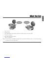
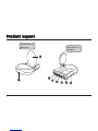
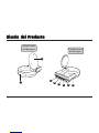
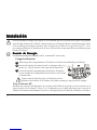
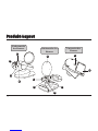
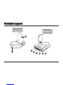
•One Camera
•One Receiver
•One Audio/Video Cable (RCA to RCA for NTSC; RCA to Scart for PAL)
•Two Power Adapters
•One Quick Installation Guide
•This User's Manual
Note: Two AC adapters with different length cables are included with this product. Use either depending
on distance from the wall outlet.
Receiver
English
1
Camera


Product LayoutProduct Layout
Product LayoutProduct Layout
Product Layout
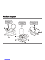
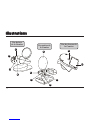
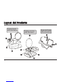
Infrared LEDs
Eight LEDs to provide infrared light for night vision.
Lens
Focuses image automatically without any adjustment.
Lens Body
Rotates up to 180 degrees.
Microphone
2.4 GHz Audio/Video Antenna (Front )
Transmits audio/video signals. Caution: Antenna does not rotate freely through 360 degrees. (See "Orienting
Units for Optimal Performance", on page 13)
Channel Selection Switch
Select the channel by sliding the slide switch to the channel number you want.
Must select the same channel on both the camera and receiver.
Power Indicator LED
OFF/ON/NIGHT
POWER ON/POWER OFF and NIGHT VISION ON switch.
9V Power Adapter Plug
Mounting Hole
Battery Compartment
1
2
3
4
5
6
7
8
9
10
3
11


Product LayoutProduct Layout
Product LayoutProduct Layout
Product Layout
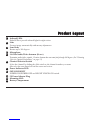
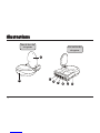
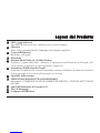
Power Indicator LED
The LED should be lit when the ON/OFF switch is in the ON position..
2.4GHz Audio/Video Antenna (Front )
Transmits and receives Audio/Video signals. Caution: Antenna does not rotate freely 360 degrees. (See
"Orienting Units for Optimal Performance", on page 13)
Channel Selection Dipswitches
Select the channel by setting the channel dipswitch to the ON position. The number 5 dipswitch
sets the timer for the auto-sequence function (see "Auto-Sequence Function for Multiple Location
Monitoring", on page 14).
Must select the same channel both on camera and receiver.
Left Audio Jack (White)
Right Audio Jack (Red)
Video Jack (Yellow)
9V Power Adapter Plug
ON/OFF Switch
1
2
3
4
5
6
7
8
5

Setting UpSetting Up
Setting UpSetting Up
Setting Up
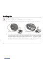
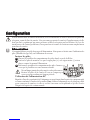
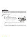
Before you make the connection:
•Always make sure the unit ON/OFF switch is in the OFF position.
•Set the channel switches on the back of the camera and receiver to the same channel.
•If you wish to wall mount the camera, it is recommended that the receiver reception be
tested before fixing in place. Have one person hold the camera against the wall in the
selected mounting area while another checks reception on the TV. If interference or other
problems are present, refer to the Troubleshooting section on page 16 of this manual. You
may need to select a different location in the room for mounting the camera.
Receiver
Camera
6

Setting Up-CameraSetting Up-Camera
Setting Up-CameraSetting Up-Camera
Setting Up-Camera
Power SupplyPower Supply
Power SupplyPower Supply
Power Supply
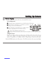
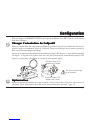
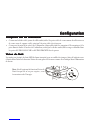
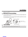
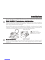
1The camera uses either batteries (AA-size) or household AC current.
To Load Batteries
Open the battery compartment cover in the direction of the arrow.
Slide the POWER Switch to the ON position. The LED on the back of the camera should light.
Never mix old batteries with new ones.
Remove batteries from the camera if you do not plan to use it for a period of time.
Using AC Power
Plug one end of the provided power adapter into a wall outlet and the other end into the rear
of the camera. Note: Use the adapter with the longer cable to connect the camera if the
camera is mounted on a ceiling or wall at a long distance from the wall outlet.
Insert batteries so their plus (+) and minus (-) ends are
facing as shown in the illustration.
Close the battery compartment cover. Make sure the
battery compartment cover is locked securely.
7
1
2
3

Setting Up-CameraSetting Up-Camera
Setting Up-CameraSetting Up-Camera
Setting Up-Camera
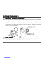
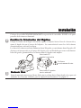
2Changing the Lens OrientationChanging the Lens Orientation
Changing the Lens OrientationChanging the Lens Orientation
Changing the Lens Orientation
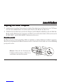
Place the camera in a convenient location, point the lens towards the observation area and adjust
the angle by rotating the lens body. The camera's auto focus feature automatically focuses the
image.
The camera's head rotates horizontally up to 200 degrees and vertically up to 30 degrees. The
lens is built into a lens body that is designed to rotate vertically up to 180 degrees, allowing the
camera to cover the widest angles.
3Fine TuningFine Tuning
Fine TuningFine Tuning
Fine Tuning
Adjust the antenna so that the front (curved side) faces the room where the receiver is to be set
up. See "Orienting Units for Optimal Performance", on page 13.
Do not apply excessive force when rotating.
Doing so can cause serious damage to the camera.
Rotates up to 90
towards the back
Rotates up to 90
towards the front
8

Setting Up-ReceiverSetting Up-Receiver
Setting Up-ReceiverSetting Up-Receiver
Setting Up-Receiver
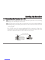
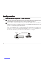
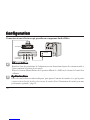
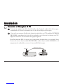
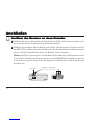
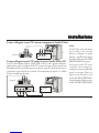
Connect one set of audio/video cables to the audio/video jacks of the receiver, matching
the plug colors with the jacks on the receiver.
Connect the other end of the cable to the audio/video jacks on the TV labeled LINE IN,
matching the plug colors with the jacks on the TV. Some connection scenarios are shown
on the next page.
Note: For PAL systems, the connector on the audio/video component is a Scart socket.
Connect the Scart connector labeled RECEIVER to the Scart socket labeled IN on the
audio/video component; connect the RCA connector to the receiver.
11
11
1Connecting the Receiver to a TVConnecting the Receiver to a TV
Connecting the Receiver to a TVConnecting the Receiver to a TV
Connecting the Receiver to a TV
Receiver
Audio/Video
Component
RCA to Scart Cable
Receiver
9
1
2

Setting Up-ReceiverSetting Up-Receiver
Setting Up-ReceiverSetting Up-Receiver
Setting Up-Receiver
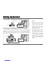
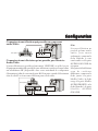
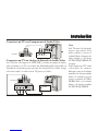
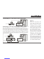
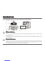
Connecting to a TV With an Audio/Video Component
Receiver
Connecting to a TV Without Audio/Video IN Jacks
If your TV has UHF/VHF input only, and there is no audio/video
equipment near your TV, you will need to get an RF-Modulator
(available at your local electronic store) to convert the RCA jacks to
coax. Then select either channel 3 or 4 on your TV to view the video.
Note:
If the TV has only one input
for audio (mono sound
only), connect the white
plug to that single audio
input and to the receiver's
AUDIO LEFT jack.
If the jacks on the TV are
colored differently, connect
the yellow plug to the jack
labeled Video, the red plug
to the jack labeled AUDIO
RIGHT, and the white plug
to the jack labeled AUDIO
LEFT.
VIDEO AUDIO
RF OUT
TV
RF Modulator
CH 3/4 VHF/UHF
TV
VIDEO AUDIO IN
Receiver
10

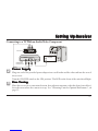
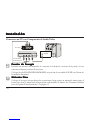
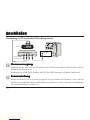
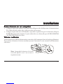
Plug one end of the provided power adapter into a wall outlet and the other end into the rear of
the receiver.
Turn the ON/OFF switch to the ON position. The LED on the front of the unit should light.
Place the receiver in a convenient location, then adjust its antenna so that the front (curved face)
faces the room where the camera is set up. See "Orienting Units for Optimal Performance", on
page 13.
Connecting to a TV With an Audio/Video Component
Setting Up-ReceiverSetting Up-Receiver
Setting Up-ReceiverSetting Up-Receiver
Setting Up-Receiver
2
3
Receiver
VIDEO AUDIO
RF OUT
TV
Audio/Video
Component
VHF/UHF
Power SupplyPower Supply
Power SupplyPower Supply
Power Supply
Fine TuningFine Tuning
Fine TuningFine Tuning
Fine Tuning
11

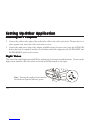
Setting Up-Other ApplicationSetting Up-Other Application
Setting Up-Other ApplicationSetting Up-Other Application
Setting Up-Other Application
Receiving on a ComputerReceiving on a Computer
Receiving on a ComputerReceiving on a Computer
Receiving on a Computer
•Connect the yellow video plug of the audio/video cable to the video jack on the TV tuner device or
video capture card, and to the video jack of the receiver.
•Connect the mini stereo plug of the adapter (available in any electronic store) into the AUDIO IN
jack on the back of computer, and the red and white audio/video plugs into the AUDIO LEFT and
AUDIO RIGHT jacks on the receiver.
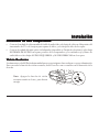
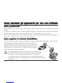
Night VisionNight Vision
Night VisionNight Vision
Night Vision
The camera has eight high-intensity LEDs for picking up clear images in unlit locations. To turn on the
night vision function, slide the switch as shown in the illustration on the right.
Note: Turning the night vision function
off when not required will save power.
12

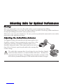
Orienting Units for Optimal PerformanceOrienting Units for Optimal Performance
Orienting Units for Optimal PerformanceOrienting Units for Optimal Performance
Orienting Units for Optimal Performance
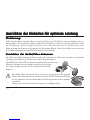
Placing:Placing:
Placing:Placing:
Placing:
Place the camera and receiver on a flat, stable surface to prevent damage from falling.
For optimal performance, try to place the units as high as possible to avoid any possible interference
from people walking between the camera and the receiver.
Microwave ovens can cause interference. Be sure you do not position the camera and receiver with a
microwave in the path between them.
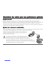
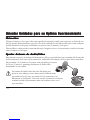
Adjusting the Audio/Video AntennasAdjusting the Audio/Video Antennas
Adjusting the Audio/Video AntennasAdjusting the Audio/Video Antennas
Adjusting the Audio/Video Antennas
For optimal reception, the antennas on both camera and receiver
should be oriented. In most situations the curved face of the
audio/video antennas on both the transmitter and receiver
should be facing each other. If the camera and receiver are less
than 10 feet (3 meters) apart, keep the audio/video antennas flat
in their casings.
13
The audio/video antennas have been designed to pivot but have limited
rotation in either clockwise or counterclockwise directions. Antenna does
not rotate freely 360 degrees. Rotating past the point where resistance is felt
will result in permanent damage to both antenna and mechanical stopper.

Auto-Sequence Function for Multiple Location MonitoringAuto-Sequence Function for Multiple Location Monitoring
Auto-Sequence Function for Multiple Location MonitoringAuto-Sequence Function for Multiple Location Monitoring
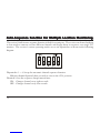
Auto-Sequence Function for Multiple Location Monitoring
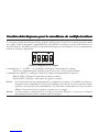
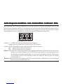
The receiver's built in auto-sequence function is ideal for security use. The receiver can be used with up
to four wireless cameras on four different channels and display them in sequence on a single TV/
monitor. The receiver's various operating modes are set via dipswitches as shown in the following
diagram:
Dipswitches 1 ~ 4: Set up the automatic channel sequence function
Slide the channel dipswitch that you wish to view to the ON position.
Diswitch 5: Sets the sequence change interval time
ON: Changes channel every eight seconds.
OFF: Changes channel every four seconds.
Factory-Preset Mode
14

Auto-Sequence Function for Multiple Location MonitoringAuto-Sequence Function for Multiple Location Monitoring
Auto-Sequence Function for Multiple Location MonitoringAuto-Sequence Function for Multiple Location Monitoring
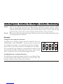
Auto-Sequence Function for Multiple Location Monitoring
Note 1: The receiver will auto detect the receiving channels, and display them in sequence. When
only one channel dip switch is in the ON position, the receiver will receive the channel
continuously, without regard to the position of the 5th dip switch. If more than one dip
switch remains on, the auto-sequence function will continue on those channels.
Note 2: When none of the dip switches are in the ON position, the receiver will automatically set the
receiving channel to Channel 1.
Example:
Using the auto-sequence function:
If you have two wireless camera and their channels are set on
CHANNEL 1 and CHANNEL 3, and you wish to monitor the
two channels in sequence, you must slide up the first and third
dip switches to the ON position (see the diagram on the right).
If you wish these two channels to be alternated at eight-second
intervals, slide the DIP 5 switch to the ON position. Leave it in the
lower position for four-second channel change intervals.
15
Stopping the auto-sequence function:
To stop the auto-sequence function and lock on one channel, leave
the dip switch for the channel you want to receive in the ON
position. Slide the others to the lower position.

TroubleshootingTroubleshooting
TroubleshootingTroubleshooting
Troubleshooting
If you are not getting any signal at allIf you are not getting any signal at all
If you are not getting any signal at allIf you are not getting any signal at all
If you are not getting any signal at all
•Check that the receiver is properly connected to the TV which you want to receive the signal
•Check the power ON/OFF switches on the camera and receiver
•Check power switches on the TV
•Make sure power plugs are pushed all the way in.
•Check all cable connections.
•Check the CHANNEL switch on both camera and receiver are set to the same number
•If you connect the receiver to a TV through an RF modulator, check that the TV is tuned to the
same channel as the TV Channel switch on the RF modulator (3 or 4)
If the signal is poor, or there is interferenceIf the signal is poor, or there is interference
If the signal is poor, or there is interferenceIf the signal is poor, or there is interference
If the signal is poor, or there is interference
•Adjust the antennas orientation (see "Orienting Units for Optimal Performance", on page 15)
•Change the channel on both camera and receiver and make them the same.
•If there is a microwave oven in use in the path between the camera and receiver, remove the
microwave oven or turn it off
•Make sure the camera and receiver are within range (up to 300 feet)
•Check the channel dipswitch positions on the receiver
16

Care and MaintenanceCare and Maintenance
Care and MaintenanceCare and Maintenance
Care and Maintenance
•For best performance, don't touch the antennas unnecessarily
•Keep all its parts and accessories out of young children's reach
•Camera performances can be adversely affected by fingerprints or dirt on the lens surface. Avoid
touching the lens surface with your fingers.
•Should the lens become dirty, use a blower to blow off dirt and dust, or a soft, dry cloth to wipe off
the lens.
•Keep dry. Precipitation, humidity, and liquids, contain minerals that will corrode electronic circuits
•Do not use or store in dusty, dirty areas. Moving parts may be damaged
•Do not store in hot areas. High temperatures can shorten the life of electronic devices and warp or
melt certain plastics
•Do not store in very cold areas. When the Wireless Camera System warms up (to its normal
temperature), moisture can form inside the case, which may damage electronic circuit boards
•Do not attempt to open the case. Non-expert handling of the device may damage it
•Do not drop , knock, or shake it. Rough handling can break internal circuit boards
•Do not use harsh chemicals, cleaning solvents, or strong detergents when cleaning. Wipe with a
soft cloth slightly dampened in a mild soap-and-water solution
•If the Wireless Camera System is not working properly, take it to your nearest qualified service
facility. The personnel there will assist you, and if necessary, arrange for service
•Operate this product using only the power supply included with it or provided as an accessory
•Do not overload electrical outlets or extension cords as this can result in fire or electric shock
17

18
FCC StatementFCC Statement
FCC StatementFCC Statement
FCC Statement
This equipment has been tested and found to comply with the limits for a Class B digital device, pursuant to Part 15 of the FCC Rules. These limits are
designed to provide reasonable protection against harmful interference in a residential installation. This equipment generates, uses and can radiate radio
frequency energy and, if not installed and used in accordance with the instructions, may cause harmful interference to radio communications. However,
there is no guarantee that interference will not occur in a particular installation. If this equipment does cause harmful interference to radio or television
reception, which can be determined by turning the equipment off and on, the user is encouraged to try to correct the interference by one or more of the
following measures:
•Reorient or relocate the receiving antenna
•Increase the separation between the equipment and receiver
•Connect the equipment into an outlet on a circuit different from that to which the receiver is connected
•Consult the dealer or an experienced radio/TV technician for help
FCC Label Compliance Statement:
This device complies with Part 15 of the FCC Rules. Operation is subject to the following two conditions: (1) this device may not cause harmful
interference, and (2) this device must accept any interference received, including interference that may cause undesired operation.
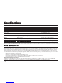
Frequency 2.4~2.4835 GHz 2.4~2.4835 GHz
Range 300 feet (100 meters) clear line of sight 300 feet (100 meters) clear line of sight
Antennas Directional circular-polarized antenna Directional circular-polarized antenna
Channel 4 selectable channels 4 selectable channels
AV mod/demod. method FM FM
Image Sensor -- 1/4” CMOS image sensor
Lens -- f 3.6, F 2.0
Audio Stereo audio input and output --
Video Composite video input and output --
Dimensions 14 x 11 x 2.8 cm (5.5 x 4.3 x 1.1 in) 10 x 9 x 15 (3.9 x 3.5x5.9 in)
Weight 200g (7.1 ounces) 300 g (10.6 ounces) without batteries
Operating remperature 10°C~50°C (14° F~122° F) 10°C~50°C (14° F~122° F)
SpecificationsSpecifications
SpecificationsSpecifications
Specifications
Receiver Camera
Specifications are subject to change without notice.
Declaration of ConformityDeclaration of Conformity
Declaration of ConformityDeclaration of Conformity
Declaration of Conformity
Hereby, TRANWO TECHNOLOGY CORP., declares that this GigaAir 3010 is in compliance with the essential requirements and other relevant provisions
of Directive 1999/5/EC.
La pagina sta caricando ...
La pagina sta caricando ...
La pagina sta caricando ...
La pagina sta caricando ...
La pagina sta caricando ...
La pagina sta caricando ...
La pagina sta caricando ...
La pagina sta caricando ...
La pagina sta caricando ...
La pagina sta caricando ...
La pagina sta caricando ...
La pagina sta caricando ...
La pagina sta caricando ...
La pagina sta caricando ...
La pagina sta caricando ...
La pagina sta caricando ...
La pagina sta caricando ...
La pagina sta caricando ...
La pagina sta caricando ...
La pagina sta caricando ...
La pagina sta caricando ...
La pagina sta caricando ...
La pagina sta caricando ...
La pagina sta caricando ...
La pagina sta caricando ...
La pagina sta caricando ...
La pagina sta caricando ...
La pagina sta caricando ...
La pagina sta caricando ...
La pagina sta caricando ...
La pagina sta caricando ...
La pagina sta caricando ...
La pagina sta caricando ...
La pagina sta caricando ...
La pagina sta caricando ...
La pagina sta caricando ...
La pagina sta caricando ...
La pagina sta caricando ...
La pagina sta caricando ...
La pagina sta caricando ...
La pagina sta caricando ...
La pagina sta caricando ...
La pagina sta caricando ...
La pagina sta caricando ...
La pagina sta caricando ...
La pagina sta caricando ...
La pagina sta caricando ...
La pagina sta caricando ...
La pagina sta caricando ...
La pagina sta caricando ...
La pagina sta caricando ...
La pagina sta caricando ...
La pagina sta caricando ...
La pagina sta caricando ...
La pagina sta caricando ...
La pagina sta caricando ...
La pagina sta caricando ...
La pagina sta caricando ...
-
 1
1
-
 2
2
-
 3
3
-
 4
4
-
 5
5
-
 6
6
-
 7
7
-
 8
8
-
 9
9
-
 10
10
-
 11
11
-
 12
12
-
 13
13
-
 14
14
-
 15
15
-
 16
16
-
 17
17
-
 18
18
-
 19
19
-
 20
20
-
 21
21
-
 22
22
-
 23
23
-
 24
24
-
 25
25
-
 26
26
-
 27
27
-
 28
28
-
 29
29
-
 30
30
-
 31
31
-
 32
32
-
 33
33
-
 34
34
-
 35
35
-
 36
36
-
 37
37
-
 38
38
-
 39
39
-
 40
40
-
 41
41
-
 42
42
-
 43
43
-
 44
44
-
 45
45
-
 46
46
-
 47
47
-
 48
48
-
 49
49
-
 50
50
-
 51
51
-
 52
52
-
 53
53
-
 54
54
-
 55
55
-
 56
56
-
 57
57
-
 58
58
-
 59
59
-
 60
60
-
 61
61
-
 62
62
-
 63
63
-
 64
64
-
 65
65
-
 66
66
-
 67
67
-
 68
68
-
 69
69
-
 70
70
-
 71
71
-
 72
72
-
 73
73
-
 74
74
-
 75
75
-
 76
76
-
 77
77
-
 78
78


TRANWO Technology 3010 Manuale utente
- Tipo
- Manuale utente
- Questo manuale è adatto anche per
in altre lingue
- English: TRANWO Technology 3010 User manual
- français: TRANWO Technology 3010 Manuel utilisateur
- español: TRANWO Technology 3010 Manual de usuario
Altri documenti
-
SWITEL BC109 Manuale del proprietario
-
Tranwo Technology Corp O6LTTA-36T Manuale utente
-
-
-
Marmitek Megaview70 Manuale utente
-
-
Marmitek A/V transmitters Wireless: GigaVideo 45 Manuale utente