
Rel. 1
User and maintenance manual
ENGLISH
ELECTRICAL BOARDS FOR REFRIGERATING INSTALLATIONS
REV. 01-23
ENG
NEXUS P20
Driver for ON/OFF electronic expansion valve
READ AND KEEP

Pag. 2
Rev. 01-23
USER AND MAINTENANCE MANUAL

NEXUS P20
Pag. 3
Rev. 01-23
USER AND MAINTENANCE MANUAL
INTRODUCTION
Page 4 1.1 General
Page 4 1.2 Product identification codes
Page 5 1.3 Overall dimensions
Page 5 1.4 Identification data
INSTALLATION
Page 6 2.1 General warnings for the installer
Page 6 2.2 Mechanical fixing
TECHNICAL FEATURES
Page 7 3.1 Technical features
WARRANTY TERMS
Page 8 4.1 Warranty terms
DATA PROGRAMMING
Page 9 5.1 Display description
Page 10 5.2 MyPego app interface
Page 13 5.2.1 Connections setup
Page 18 5.2.2 Instrument sharing
Page 19 5.3 Web interface / http access
Page 23 5.4 Remote console interface (optional)
Page 23 5.4.1 Remote console icons (optional)
Page 24 5.4.2 Remote Console Key Combination (Optional)
Page 25 5.5 ESH set point setting and display
Page 26 5.6 First level programming
Page 26 5.7 First level parameter list
Page 28 5.8 Second level programming
Page 28 5.9 Second level parameter list
Page 32 5.9.1 Valve management (EEV parameter)
Page 33 5.10 Quick view menu (read-only)
Page 33 5.11 Quick view menu parameter list (read-only)
Page 33 5.12 Refrigerant temperature table
Page 34 5.13 Password function
Page 34 5.14 Software update
Page 34 5.15 Parameters export/import
OPTIONS
Page 35 6.1 TeleNET monitoring/supervision system
Page 35 6.2 Network configuration with Modbus-RTU protocol
DIAGNOSTICS
Page 36 7.1 Diagnostics
ANNEXES
Page 37 A.1 EU Declaration of Conformity
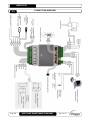
Page 38 A.2 Connection diagram
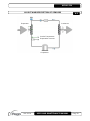
Page 39 A.3 Layout and description of sensors
CHAP. 1
CHAP. 2
CHAP. 3
CHAP. 4
CHAP. 5
CHAP. 6
CHAP. 7
CONTENTS

Pag. 4
Rev. 01-23
USER AND MAINTENANCE MANUAL
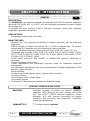
GENERAL
DESCRIPTION:
The NEXUSP20 is an electronic regulator for controlling the ON/OFF electronic expansion
valve with 230/110/24 VAC or 24 VDC coil, with integrated connectivity functions through
the myPego app.
It manages the most common ON/OFF electronic expansion valves and integrates
evaporator superheat management.
APPLICATIONS:
- Refrigerated counters and cold rooms.
MAIN FEATURES:
- Bluetooth, Wi-Fi and ethernet connectivity for installer interaction with the driver and
diagnostics.
- Without console on board: the myPego APP is used for programming. An external
console with IP65 protection can be connected as a service terminal.
- ON/OFF electronic expansion valve control with 230/110/24 VAC and 24 VDC coil.
- Compatible with 23 gases: R404, R134, R22, R407A, R407F, R407H, R410A, R450A,
R507, R513A, R744(CO2), R449A, R290, R32, R448A, R452A, R600, R600A, R1270,
R1234ze, R23, R717(NH3), R454C.
- RS485 serial connection with TeleNET or Modbus-RTU protocol, selectable by
parameter.
- Three configurable digital inputs.
- Suction temperature and evaporation pressure probe for evaporator superheat
management.
- Easy parameter programming with 4 pre-configurations for different applications of the
electronic expansion valve.
- Alarm signalling.
- Auxiliary relay configurable as alarm / solenoid valve command.
- Password function.
- LED indications of the system status.
- User-friendly keypad.
- USB input for Parameters export/import and Software update.
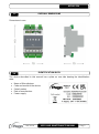
PRODUCT IDENTIFICATION CODES
NEXUSP20 Electronic regulator to control the ON/OFF electronic
expansion valve. Manages the most common 230/110/24
VAC and 24VDC ON/OFF electronic expansion valves.
Bluetooth, Wi-Fi and ethernet connectivity for installer
interaction with the driver and Diagnostics. Evaporator
superheat management.
200NANOTTL01 TTL remote console (optional).
CHAPTER 1: INTRODUCTION
1.2
1.1

NEXUS P20
Pag. 5
Rev. 01-23
USER AND MAINTENANCE MANUAL
OVERALL DIMENSIONS
Dimensions in mm.
IDENTIFICATION DATA
The device described in this manual has a plate on one side bearing the identification
data:
• Name of Manufacturer
• Code and model of the device
• Serial number
• Date of manufacture
• Power supply
1.3
1.4

NEXUS P20
Pag. 6
Rev. 01-23
USER AND MAINTENANCE MANUAL
GENERAL WARNINGS FOR THE INSTALLER
1. Install the device in places that respect its degree of protection.
2. Avoid using multi-pole cables with conductors connected to inductive and power
conductors and signal conductors like sensors and digital inputs.
3. Avoid putting in the same channels, power cables with signal cables (sensors and
digital inputs).
4. Reduce the lengths of the connection cables as much as possible, preventing the
wiring from taking the spiral shape harmful for possible inductive effects on electronics.
5. All electric cables used in wiring must be properly proportionate to support the load
that must feed.
6. If it’s necessary to prolong the probes cable, the use of appropriate section
conductors, and in any case not less than 1mm², is necessary. The extension or
shortening of the probes could alter the factory calibration. Then proceed with the
verification and calibration by means of an external thermometer.
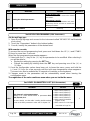
MECHANICAL FIXING
Place the Module on DIN guide and close the
lower hook to block it on it.
Make all electric connections
according to the attached patterns
for the corresponding model (see
the relative tables in attachments).
During the wiring it is recommended to keep
the power cables away from those of the
signal.
2.1
CHAPTER 2: INSTALLATION
2.2

NEXUS P20
Pag. 7
Rev. 01-23
USER AND MAINTENANCE MANUAL
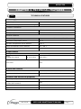
TECHNICAL FEATURES
Power supply
Main Voltage
24 V~ 10% 50-60Hz
Max power consumption (electronic control only)
~ 7 VA
Climatic conditions
Operating temperature
-5T50°C <90% R.H. non-condensing
Storage temperature
-10T70°C <90% R.H. non-condensing
General features
Compatible types of temperature sensor
Temperature sensors: NTC 10K 1% / PTC / PT1000
Resolution of temperature sensors
0,1 °C
Precision of temperature sensor detection
± 0,5 °C
Range of temperature sensor detection
-45 ÷ +99 °C
Compatible type of pressure sensor
Pressure sensor: 4/20mA
Output features
Description
Features of output board
Alarm
(voltage-free contact)
(8A AC1 Relay)
8(3)A 250V~
Pulse valve
Triac
Dimensional features
Dimensions
12.15cm x 7.1cm x 10.5cm (HxPxL)
Remote console dimensions (optional)
3.7cm x 2.31cm x 9.3cm (HxPxL)
Insulation and mechanical properties
Nexus degree of protection
IP20
Degree of protection of the front of the remote
console (front mounted)
IP65
Material of boxes
UL94 V-0 self-extinguishing PC+ABS
Type of insulation
II Class
CHAPTER 3: TECHNICAL FEATURES
3.1

NEXUS P20
Pag. 8
Rev. 01-23
USER AND MAINTENANCE MANUAL
WARRANTY TERMS
The NEXUS electronic controls are covered by a 24-months warranty against all
manufacturing defects as from the date indicated on the product ID code.
In case of defect the product must be appropriately packaged and sent to our production
plant or to any authorized Service Center with the prior request of the Return Authorization
Number.
Customers are entitled to have defective products repaired, spare parts and labour
included. The costs and the risks of transport are at the total charge of the Customer.
Any warranty action does not extend or renew its expiration.
The Warranty does not cover:
• Damages resulting from tampering, impact or improper installation of the product and
its accessories.
• Installation, use or maintenance that does not comply with the instructions provided
with the product.
• Repair work carried out by unauthorized personnel.
• Damage due to natural phenomena such as lightning, natural disasters, etc.
In all these cases the costs for repair will be charged to the customer.
The intervention service in warranty can be refused when the equipment is modified or
transformed.
Under no circumstances Pego S.r.l. will be liable for any loss of data and information,
costs of goods or substitute services, damage to property, people or animals, loss of sales
or earnings, business interruption, any direct, indirect, incidental, consequential,
damaging, punitive, special or consequential damages, in any way whatsoever caused,
whether they are contractual, extra contractual or due to negligence or other liability arising
from the use of the product or its installation.
Malfunction caused by tampering, bumps, inadequate installation automatically declines
the warranty. It is compulsory to observe all the instructions in this manual and the
operating conditions of the product.
Pego S.r.l. disclaims any liability for possible inaccuracies contained in this manual if due
to errors in printing or transcription.
Pego S.r.l. reserves the right to make changes to its products which it deems necessary
or useful without affecting its essential characteristics.
Each new release of the PEGO product user manual replaces all the previous ones.
As far as not expressly indicated, is applicable the Law and in particular the art. 1512 C.C.
(Italian Civil Code).
4.1

NEXUS P20
Pag. 9
Rev. 01-23
USER AND MAINTENANCE MANUAL
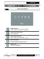
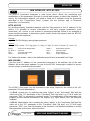
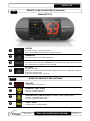
DISPLAY DESCRIPTION
ENABLING ICON
Led OFF = Enable input OFF (see In1/2/3 configuration)
Led ON = Enable input ON (see In1/2/3 configuration)
EEV OUTPUT STATUS ICON
Led OFF = Valve closed
Led ON = Valve open
WEB CONNECTION ICON
Led OFF = Internet connection not active
Led ON = Internet connection active (Wi-Fi or ethernet)
BLUETOOTH ICON
LED OFF = Bluetooth off
Flashing LED = Bluetooth on, waiting for connection
Led ON = Bluetooth on, smartphone connected
ALARM ICON
Led OFF = No alarm present
Flashing LED = Alarm present
CHAPTER 5: DATA PROGRAMMING
5.1

NEXUS P20
Pag. 10
Rev. 01-23
USER AND MAINTENANCE MANUAL
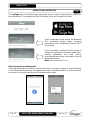
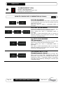
MYPEGO APP INTERFACE
The myPego app is the official Pego application for the control and supervision of NEXUS
line instruments. It is available for free on the App Store and Google Play Store.
Direct connection to the device via Bluetooth
BLE; monitoring system status; changing
parameters and configuring Ethernet Wi-Fi
connectivity.
Cloud connection: monitoring of the status of
all devices registered in the subscription plan;
reading parameters and daily history;
receiving real-time alarm notifications from all
registered devices.
Note: full control with cCL=2.
Direct connection via Bluetooth
Choosing Bluetooth Connection, accesses the direct connection pages. Enable Bluetooth
on the instrument by pressing the appropriate button (see attachment A.2) and confirm the
connection in the app to access the instrument status page.
5.2

NEXUS P20
Pag. 11
Rev. 01-23
USER AND MAINTENANCE MANUAL
Connecting to Cloud Device
Choosing the Cloud Connection accesses the tool selection page. Here it is possible to
select which of the registered instruments (through the procedure indicated in the previous
chapter) it is possible to access to monitor the status of the system.
The icon indicates that the tool is successfully transmitting data to the cloud. Tap the
name of a tool to access its status page.
Note: If the icon is grey, it may be necessary to set the date and time correctly on the
instrument (parameters Hr, min, Yr, Mo, dy).
NEXUS P20 instrument status
Once logged in (via Bluetooth if it’s a nearby instrument or via Cloud if it’s a remote
instrument) the NEXUSP20 status page opens.
Here it’s possible to:
- Read the current superheat value.
- Read the setpoint and modify it (if connected via Bluetooth or if cCL=2).
- Check the status of inputs/outputs/alarms.
- Verify the main quantities relating to the expansion in the evaporator, in real time:
- tS4: suction probe temperature
- tS5: evaporation temperature (converted)
- PS5: evaporation pressure
- oEV: electronic valve opening %

NEXUS P20
Pag. 12
Rev. 01-23
USER AND MAINTENANCE MANUAL
By touching the keys on the bottom bar it’s possible to access the other configuration
pages:
- Info page
It contains the basic information of the
instrument and the name by which the
instrument is identified on the Cloud.
Current superheating
Valve is open
Enable input
Defrost input
Adjustment information
Superheating setpoint
Output status
Input status
Menu bar
Instrument name on cloud,
editable if connected via
Bluetooth.
Manual: link to download
the user manual in pdf.

NEXUS P20
Pag. 13
Rev. 01-23
USER AND MAINTENANCE MANUAL
- Parameters page
- Cloud page
Allows the configuration of the
connection to the cloud and the
network settings (see the Chapter
Connections setup).
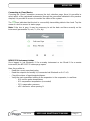
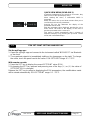
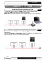
CONNECTIONS SETUP
The NEXUS controller is equipped with Bluetooth BLE, Wi-Fi or ethernet connectivity for
management or monitoring via remote devices (tablet, smartphone, PC).
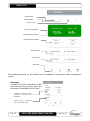
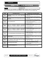
In particular, the remote management of the device takes place in the following ways:
Distance
Support
Channel
Mode
MyPego app
(BLE)
approx. 50m
Smartphone, Tablet
Bluetooth BLE
Control and monitoring
MyPego app
(Cloud)
---
Smartphone, Tablet
Wi-Fi, Ethernet
Real-time monitoring and
notifications.
Control, if cCL=2.
Integrated
webserver
---
Smartphone, Tablet, PC
Wi-Fi, Ethernet
Control (with cSL=2) and
monitoring. Network
configuration required.
The myPego app is available on Google and Apple stores for free.
It allows complete control of the NEXUS instrument and is necessary to carry out the basic
operations to connect the device to the Internet (IP address check, Wi-Fi username and
password entry, etc.). Through the same application it’s possible to receive notifications
from NEXUS instruments in the event of an alarm and monitor the status of the registered
devices (subscription function, see the dedicated chapter).
Level selection:
tap to change parameter level
Parameter identifier
Parameter description
Parameter value: touch to modify
(only with cCL=2)
5.2.1

NEXUS P20
Pag. 14
Rev. 01-23
USER AND MAINTENANCE MANUAL
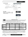
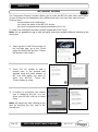
To connect the NEXUS instrument to the internet via Wi-Fi or ethernet, do the following:
1) Download the myPego app from the Google/Apple store and install it on a
smartphone/tablet.
2) Activate Bluetooth on the NEXUS instrument with the dedicated activation key. The
flashing icon activates.
3) Open the myPego app and access the
Bluetooth section.
4) Touch the "Scan” key and the "Confirm” key to make the connection. The Bluetooth icon
on the instrument turns on steady to signal the connection.
5) The homepage of the application opens, where it is possible to see the superheat and
consult the status of the inputs and outputs.
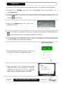
6) In the selection bar below, tap the “Cloud” icon
to access the network configuration menu.
7) Upon first sign in, the myPego app prompts
setting up of your Cloud connection. If relevant,
continue by pressing the “Ok” key otherwise
press “Cancel” and skip directly to step 14).

NEXUS P20
Pag. 15
Rev. 01-23
USER AND MAINTENANCE MANUAL
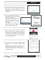
8) By clicking “Ok” in the previous point, the Login
page opens. If already registered, enter the
registration e-mail and password and click
Login. Otherwise click "Sign in" to make the first
registration.
9) If you are registering for the first
time, please enter a valid e-mail
address and password.
A verification email will be sent to
the address indicated: click on the
link in the email to confirm the
registration.
Once registration is confirmed, you
will be able to log in with the
account created (see point 8).
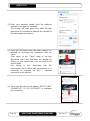
10) Once the user has been created (or logged in
with an existing user), the device must be
associated with an existing Cloud subscription;
or create a new subscription. Touch the second
link to associate the device with the registered
user's cloud subscription.
11) If the user does not have an active cloud
subscription, the subscription activation page
opens.
Select the type of plan you need based on the
number of instruments you want to monitor.
Continue with the activation of the plan through
the payment page.

NEXUS P20
Pag. 16
Rev. 01-23
USER AND MAINTENANCE MANUAL
12) Enter your payment details (only the methods
provided in the app are available).
The charge will take place only after the trial
period and it is possible to interrupt the renewal of
the subscription at any time.
13) Once the subscription plan has been created, it is
possible to associate the instrument with the
Cloud.
Then return to the "Cloud" page of the app
(Bluetooth side) and associate the device by
clicking on the second tab. Turn the NEXUS off
and on again.
The device is thus associated with the
subscription, but to allow data transmission it is
necessary to configure the Wi-Fi / Ethernet
connection to the internet.
14) Touch the last link at the bottom "DEVICE NOT
CONNECTED TO THE INTERNET" to configure
the connection.

NEXUS P20
Pag. 17
Rev. 01-23
USER AND MAINTENANCE MANUAL
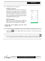
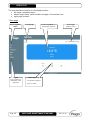
15) Configure the type of connection:
- If ethernet connection:
connect the cable to the NEXUS instrument and
set the DHCP or set the desired IP / NETMASK /
GATEWAY configuration. At the end, touch the
"Send settings" key to configure the instrument. If
DHCP is activated, it will be necessary to return
to this page after a few moments, to check the IP
received from the DHCP server.
- If Wi-Fi connection:
touch the WI-FI ON switch and configure the
SSID and password of the network to which the
NEXUS will connect. Enable DHCP if needed.
At the end of the setting, touch the "Send
settings" key.
16) At the end of the configuration, when the instrument is connected (via Wi-Fi or
ethernet) the icon is activated (after about one minute). You may need to power
cycle your NEXUS.
17) If the Cloud connection was configured (see point 13), after a few moments the
icon is activated to signal that the device is correctly sending data to the Pego Cloud.

NEXUS P20
Pag. 18
Rev. 01-23
USER AND MAINTENANCE MANUAL
INSTRUMENT SHARING
The "Instrument Sharing" function allows you to share the NEXUS with other users (up to
3) even if they are not subscribers (it’s sufficient that each user has their own account).
Sharing users:
- receive alarms and notifications.
- can check the status of the NEXUS device.
- can send commands and modify parameters (if cCL=2).
To share, the instrument must be correctly registered in the Cloud.
Note: It’s not possible to log in with the same user from multiple different devices at the
same time.
1) Open the tool in the Cloud section of
the myPego app, go to the Cloud
page and select the last link ("Share
the device in the Cloud”).
2) Touch the (+) symbol to add a
shared user; in the window that
appears enter the email address of
the user with whom you want to
share the NEXUS. Touch the
"Share" button to share.
3) If sharing is successful, the shared
user is added to the list. You can
share your NEXUS with up to three
users.
Note: the owner can stop sharing at any
time by touching the icon next to the
shared user.
5.2.2

NEXUS P20
Pag. 19
Rev. 01-23
USER AND MAINTENANCE MANUAL
WEB INTERFACE / HTTP ACCESS
The NEXUS instrument integrates a web server which allows the monitoring and
modification of the parameters through a normal web browser or direct http interface. To
access the instrument's website, you need to know its IP address using the procedure
described in the "Connections setup" chapter (via the myPego app => Bluetooth
connection => cloud card).
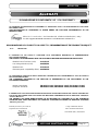
HTTP ACCESS
By sending properly formatted requests with the http protocol to the IP address of the
device, it is possible to access information in real time, change parameters, send
commands, etc. Access to this feature is password protected. Below is an example of
communication between a third-party system (which sends the request) and the NEXUS
(which sends the response).
Request:
http://IP1.IP2.IP3.IP4/ajax_data.cgi?pgd=’passcode’
Answer:
{"temp":"23.8","sttmp":"-0.5","bg_temp":"1","stby":"0","ligh":"0","def":"0","almst":"0","recst":"0"}
temp = current room temperature sttmp = temperature setpoint
bg_temp = reserved stby = stand-by status
ligh = cold room light status def = defrost status
almst = alarm present recst = active registrations
For further information, refer to the dedicated manual to be requested from Pego.
WEB SERVER
Type the local IP address of the connected instrument in the address bar of the web
browser: the access page appears. Access to the NEXUS homepage is subject to access
control using a username and password.
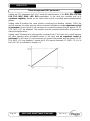
The NEXUS web pages can be accessed in two ways, based on the value of the cSL
parameter (1st level parameters):
- If cSL=1, normal user: by entering the string "admin" in the "Username" field and the
value set in the "PA" parameter in the "Password" field (1st level, e.g. if PA=6 enter the
password: "006") is accessed in read-only mode. The modification of the parameters, the
setpoint and the manual activation of the outputs (e.g. light, defrost, etc.) are therefore
inhibited.
- If cSL=2, Administrator user: inserting the string "admin" in the "Username" field and the
value set in the "PA" parameter in the "Password" field (3rd level, e.g. if PA=6 insert
password: "006") you have full access to the functions. It’s therefore possible to modify
the parameters and access all the functions.
5.3

NEXUS P20
Pag. 20
Rev. 01-23
USER AND MAINTENANCE MANUAL
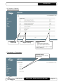
The web interface consists of a few fixed sections:
▪ left: page navigation menu.
▪ above: page name, serial number and type of connected user.
▪ right: page content.
- Main page
Alarm signalling
- red: alarm in progress
- grey: no alarm
Current superheat (and
temperature setpoint)
Page navigation
menu
Access type
(admin or user)
Current page
Logout
Logs out the user
and returns to the
login page
La pagina sta caricando ...
La pagina sta caricando ...
La pagina sta caricando ...
La pagina sta caricando ...
La pagina sta caricando ...
La pagina sta caricando ...
La pagina sta caricando ...
La pagina sta caricando ...
La pagina sta caricando ...
La pagina sta caricando ...
La pagina sta caricando ...
La pagina sta caricando ...
La pagina sta caricando ...
La pagina sta caricando ...
La pagina sta caricando ...
La pagina sta caricando ...
La pagina sta caricando ...
La pagina sta caricando ...
La pagina sta caricando ...
La pagina sta caricando ...
-
 1
1
-
 2
2
-
 3
3
-
 4
4
-
 5
5
-
 6
6
-
 7
7
-
 8
8
-
 9
9
-
 10
10
-
 11
11
-
 12
12
-
 13
13
-
 14
14
-
 15
15
-
 16
16
-
 17
17
-
 18
18
-
 19
19
-
 20
20
-
 21
21
-
 22
22
-
 23
23
-
 24
24
-
 25
25
-
 26
26
-
 27
27
-
 28
28
-
 29
29
-
 30
30
-
 31
31
-
 32
32
-
 33
33
-
 34
34
-
 35
35
-
 36
36
-
 37
37
-
 38
38
-
 39
39
-
 40
40


