La pagina si sta caricando...

www.ghibliwirbel.com
Professional Cleaning Machines Since 1968
8050817
ed. 03/2022
IT
Uso e Manutenzione
EN
Use and Maintenance
FR
Utilisation et Entretien
DE
Gebrauch und wartung
ES
Uso y Mantenimiento
PT
Uso e manutenção
NL
Gebruik en Onderhoud
CS
RU
AR
Copertina POWER LINE_8050817_2ed_10-2018.indd 1 22/10/18 08:51

www.ghibliwirbel.com
Professional Cleaning Machines Since 1968
2
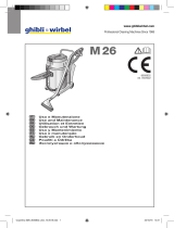
Mod.
Art.
Cap.ty
Vac mba
Air flow l/s
Nr
3
4
56
7
8
1
2
Copertina POWER LINE_8050817_1ed_04-2017.indd 2 21/04/17 09:58

www.ghibliwirbel.com
Professional Cleaning Machines Since 1968
3
1234
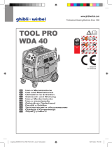
IT Produttore Modello Articolo Capacità fusto
EN Manufacturer Model Article Container capacity
FR Producteur Modèle Article Capacité de la cuve
DE Hersteller Modell Artikel
Fassungsvermögen des Körpers
ES Fabricante Modelo Artículo Capacidad del bidón
PT Produtor Modelo Artigo Capacidade do reservatório
NL Producent Model Artikel Inhoud reservoir
CS Výrobce Model Typ Obsah nádoby
RU
AR
5678
IT Capacità aspirazione Portata d’aria N° Matricola Caratteristiche elettriche
EN Vacuum Air flow Serial N° Electrical characteristics
FR Capacité d’aspiration Débit d’air N° Matricule Caractéristiques électriques
DE Ansaugleistung Luftdurchsatz Matrikelnr. Elektrische Eigenschaften
ES Capacidad de aspiración Caudal de aire N° Matrícola Características eléctricas
PT Capacidade de aspiração Caudal de ar Número de série Características elétricas
NL Zuigcapaciteit Luchtdebiet Serienummer Elektrische eigenschappen
CS Sací výkon
vzduchu Elektrické údaje
RU
AR
Copertina POWER LINE_8050817_1ed_04-2017.indd 3 21/04/17 09:58

www.ghibliwirbel.com
Professional Cleaning Machines Since 1968
4
Fig. 4
Fig. 1 Fig. 2
Fig. 10
Fig. 3
10
11
Fig. 9
Fig. 5
11
13
14
12
Fig. 6
14
16
Fig. 7
Fig. 8
8
15
16
15
3
4
1
26
7
5
17
19
20
18
19
20
19
21
22
20
9
46
Copertina POWER LINE_8050817_1ed_04-2017.indd 4 21/04/17 09:58

www.ghibliwirbel.com
Professional Cleaning Machines Since 1968
5
25
24
23
26
28
Fig. 22
27
30
34
33
36
38
37
36
35
Fig. 11 Fig. 12
Fig. 13
31
35
34
39
32
Fig. 16
Fig. 18
Fig. 19
Fig. 20 Fig. 21
Fig. 14
29
Fig. 15
Fig. 17
Copertina POWER LINE_8050817_1ed_04-2017.indd 5 21/04/17 09:58

www.ghibliwirbel.com
Professional Cleaning Machines Since 1968
6
35
40
35 40
Fig. 24
Fig. 23
41
42
Fig. 28
Fig. 27
43
44
Fig. 26
Fig. 25
Fig. 29
45
48 47
47
46
Fig. 30
Copertina POWER LINE_8050817_1ed_04-2017.indd 6 21/04/17 09:58

www.ghibliwirbel.com
Professional Cleaning Machines Since 1968
7
D 22.1 ■- 800 W 58 dbA 230 mbar 11 l 500 x 380
x 485
8,7 kg (P)
9,3 kg (I)
Ø 36 mm
WD 22.1 ■ ■ 1100 W 60 dbA 235 mbar 11 l 500 x 380
x 485
8,7 kg (P)
9,3 kg (I)
Ø 36 mm
WD 36.1
D 36.1
■ ■ 1100 W 60 dbA 235 mbar 25 l 500 x 380
x 685
8,7 kg (P)
9,3 kg (I)
Ø 40 mm
WD 50.1
D 50.1
■ ■ 1350 W 62 dbA 260 mbar 35 l 525 x 495
x 825
12,5 kg (P)
13,5 kg (I)
Ø 40 mm
WD 80.2 ■ ■ 2200 W 62 dbA 225 mbar 56 l 620 x 520
x 920
18,2 kg (P)
19,5 kg (I)
Ø 40 mm
WD 80.2 I TMT
■ ■ 2200 W 62 dbA 225 mbar 56 l 710 x 520
x 1005
20,3 kg Ø 40 mm
WD 80.2 TPT ■ ■ 2200 W 62 dbA 225 mbar 56 l 610 x 520
x 955
19 kg (P)
20,3 kg (I)
Ø 40 mm
220~240V
Copertina POWER LINE_8050817_1ed_04-2017.indd 7 20/07/17 11:00

www.ghibliwirbel.com
Professional Cleaning Machines Since 1968
8
CODICE - CODE
CODE - KENNNR.
CÓDIGO - CÓDIGO
CODE - KÓD
КОД -
زمرلا
WD 22.1 P 16538611950
16531210001
WD 22.1 I 16548711950
16544010001
WD 22.1 P EL 15688611950
15681210001
WD 36.1 P 15058611950
15051210001
WD 36.1 I 15068711950
15064010001
WD 36.1 9 EL FD 15708611950
15701210001
D 36.1 P EL 15728611950
15721210001
D 36.1 I EL 15768711950
15764010001
D 36.1 P COMBI 15748611950
15741210001
D 36.1 I COMBI 15788711950
15784010001
WD 50 . 1 P 15108611950
15101210001
WD 50.1 PD 15158611950
15151210001
WD 50.1 I 15118711950
15114010001
D 50.1 P EL 15808611950
15801210001
D 50.1 P COMBI 15408611950
15401210001
WD 80.2 P 14308611950
14301210001
WD 80.2 I 14358711950
14354010001
WD 80.2 P TPT 14408611950
14401210001
WD 80.2 I TPT 14458711950
14454010001
WD 80.2 I TMT 14438711950
14434010001
MODELLO -MODEL
MODÈLE - MODELL
MODELO - MODELO
MODEL - MODEL
МОДЕЛЬ -
زارطلا
Copertina POWER LINE_8050817_1ed_04-2017.indd 8 21/04/17 09:58

www.ghibliwirbel.com
Professional Cleaning Machines Since 1968
9
IT
Italiano ................................................................................................... ITALIANO -1
(Istruzioni originali)
EN
English ...................................................................................................ENGLISH -1
(Translation of original instructions)
FR
Français .............................................................................................. FRANÇAIS -1
(Traduction des instructions d’origine)
DE
Deutsch ................................................................................................ DEUTSCH -1
(Übersetzung der Originalanleitung)
ES
Español .................................................................................................ESPAÑOL -1
(
Traducción de las instrucciones originales
)
PT
Português ........................................................................................ PORTUGUÊS -1
(Tradução das instruções originais)
NL Nederlands ....................................................................................NEDERLANDS -1
(Vertalinig van de originele instructies)
CS
........................................................................................................ -1
(Překladoriginálníhonávodu)
RU
................................................................................................ -1
AR
...................................................................................................................... 1
( )
Copertina POWER LINE_8050817_1ed_04-2017.indd 9 21/04/17 09:58

Copertina POWER LINE_8050817_1ed_04-2017.indd 10 21/04/17 09:58

www.ghibliwirbel.com
Professional Cleaning Machines Since 1968
ITALIANO -
1
TIPO D’USO
Questi apparecchi sono stati concepiti per
aspirare solidi o liquidi o entrambi come da
tabella dati tecnici presente nella parte intro-
duttiva del manuale. Solo per questi utilizzi
sono stati concepiti.
PERICOLO:
Il costruttore non può essere ritenuto re-
sponsabile per eventuali danni dovuti ad
un uso improprio o scorretto.
Qualsiasi altro utilizzo solleva il costrut-
tore da responsabilità per danni a perso-
ne e/o cose e fa decadere qualsiasi condi-
zione di garanzia.
USO SCORRETTO
Non utilizzare l’apparecchio per:
- Aspirare sostanze infiammabili, esplosi-
ve, corrosive, tossiche.
- Aspirare sostanze calde.
- Non utilizzare l’apparecchio in versione
aspiraliquidi per aspirare polveri e vice-
versa.
Non utilizzare l’apparecchio in ambienti con
rischio di esplosione.
PREPARAZIONE
APPARECCHIO
Assemblaggio carrello
(per modelli dotati di carrello smon-
tabile)
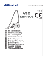
- Posizionare a terra il carrello (1 Fig. 1)
- Inserire il maniglione ( 2 Fig. 1) nel carrel-
lo.
- É possibile regolare il maniglione in altez-
za posizionando e avvitando il pomello di
fermo ( 3 Fig. 1) in corrispondenza di uno
dei due fori ( 4 Fig. 1).
- Posizionare il fusto ( 5 Fig. 2) sul carrel-
lo agganciando il supporto in plastica ( 6
Fig. 2) al tubo ( 7 Fig. 2) del carrello.
Aspirapolvere
Per apparecchi dotati di adeguati accessori.
- Sganciare le leve (8 Fig.3) e rimuovere
il coperchio (9 Fig.4) completo di gruppo
motore.
- Controllare che sia presente il filtro in
Nylon (46 Fig. 4).
- Rimuovere il filtro (10 Fig.5) in poliestere.
- Controllare, se presente, che all’interno
dell’apparecchio sia montato il sacchetto
in carta (11 Fig.5).
- Se il sacchetto in carta (11 Fig.5) non è
presente, montarlo, se necessario, agen-
do come segue:
Calzare il sacchetto in carta (11 Fig.6)
nella bocchetta (12 Fig. 6) fino a oltrepas-
sare il collare (13 Fig.6)
- Rimontare il filtro (10 Fig.5) in poliestere.
- Rimontare il coperchio e bloccarlo tramite
le leve (8 Fig.3).
- Introdurre, fino a finecorsa, il manicotto
(14 Fig. 7) del tubo di aspirazione nella
bocchetta (15 Fig. 7) presente sul fusto.
- Per sganciare il manicotto (14 Fig. 7)
spostare la levetta (16 Fig. 7) in senso
orario quindi tirare verso l’esterno il ma-
nicotto (14 Fig. 7).
- Unire all’impugnatura ergonomica (17
Fig. 8) o al tubo flessibile (18 Fig.8) a se-
conda dei modelli, la prolunga (19 Fig.8).
- Unire le due prolunghe rigide (19-20 Fig.
9) facendo coincidere i due riferimenti
(21-22 Fig. 9).
- Unire alla prolunga rigida (20 Fig.10) l’ac-
cessorio voluto (bocchetta di aspirazione,
spazzola a pennello, bocchetta a lancia,
bocchetta pavimenti ecc..).
NOTA:
Per modelli dotati di impugnatura ergonomi-
ca è possibile regolare la forza di aspirazione
agendo sul selettore (23 Fig.11).
Aprendo la nestrella (24 Fig.11) si ha una
minore azione aspirante.
Manuale POWER LINE_8050817_1ed_04-2017.indd 1 21/04/17 10:02

www.ghibliwirbel.com
Professional Cleaning Machines Since 1968
ITALIANO -
2
Collegamento elettrospazzola
Per apparecchi dotati di presa:
- Collegare la spina dell’elettrospazzola
alla presa (25 Fig. 12) presente sulla te-
stata dell’aspirapolvere (massima poten-
za consentita 200 W)
Aspiraliquidi
Per apparecchi dotati di adeguati accessori.
- Sganciare le leve (8 Fig.3) e rimuovere
il coperchio (9 Fig.4) completo di gruppo
motore.
- Controllare che sia presente il filtro in
Nylon (46 Fig. 4).
- Rimuovere il filtro (10 Fig.5) in poliestere
se presente.
- Rimuovere il sacchetto in carta (11 Fig.5)
se presente.
- Rimontare il coperchio e bloccarlo tramite
le leve (8 Fig.3).
- Introdurre, fino a finecorsa, il manicotto
(14 Fig. 7) del tubo di aspirazione nella
bocchetta (15 Fig. 7) presente sul fusto.
- Per sganciare il manicotto (14 Fig. 7)
spostare la levetta (16 Fig. 7) in senso
orario quindi tirare verso l’esterno il ma-
nicotto (14 Fig. 7).
- Unire all’impugnatura ergonomica (17
Fig.8) o al tubo flessibile (18 Fig.8), a se-
conda dei modelli, la prolunga (19 Fig.8).
- Unire le due prolunghe rigide (19-20 Fig.
9) facendo coincidere i due riferimenti
(21-22 Fig. 9).
- Unire alla prolunga rigida (20 Fig.10) l’ac-
cessorio voluto (bocchetta di aspirazione,
bocchetta pavimenti ecc...
NOTA:
Per modelli dotati di impugnatura ergonomi-
ca è possibile regolare la forza di aspirazione
agendo sulla ghiera (23 Fig.11).
Aprendo la nestrella (24 Fig.11) si ha una
minore azione aspirante.
USO DELL’APPARECCHIO
- L’apparecchio è dotato di ruote e quindi
può essere spostato tramite le apposite
maniglie, oppure spinto tramite il mani-
glione (26 Fig. 13)
- Per il suo sollevamento inserire le dita
della mano nell’apposita maniglia (27
Fig.14) ricavata sulla parte superiore del
coperchio per la versione motore singolo
oppure in due persone tramite le maniglie
(28 Fig. 13)
Avviamento dell’apparecchio
- Inserire la spina (29 Fig.15) nella presa di
corrente.
Motore singolo
- Premere l’interruttore (30 Fig.16) su “I”
per avviare il motore di aspirazione, l’in-
terruttore si illumina.
Doppio motore
- A seconda della potenza richiesta è pos-
sibile avviare un solo motore premendo
l’interruttore (31 Fig.16) su “I” oppure en-
trambe gli interruttori (31 e 32 Fig.16) se
è richiesta una maggiore forza aspirante.
Con interruttore premuto il relativo pul-
sante si illumina.
NOTA:
Quando il serbatoio di recupero è pieno, si
ha un aumento di rumore e l’apparecchio
non aspira più, quindi spegnere l’apparec-
chio e svuotare il serbatoio come descritto
nei relativi paragrafi
Spegnimento dell’apparecchio
- Premere gli interruttori (30, 31, 32 Fig.16)
su “0” per spegnere l’apparecchio; le
lampade, se presenti sugli interruttori, si
spengono.
- Staccare la spina (29 Fig.15) dalla presa
di corrente.
- Avvolgere il cavo (33 Fig.17) e aggan-
ciarlo nell’apposita sede (34 Fig.17).
Manuale POWER LINE_8050817_1ed_04-2017.indd 2 21/04/17 10:02

www.ghibliwirbel.com
Professional Cleaning Machines Since 1968
ITALIANO -
3
PULIZIA E MANUTENZIONE
PERICOLO:
Prima di effettuare qualsiasi operazione
di manutenzione rimuovere la spina dalla
presa di corrente.
Rimozione e sostituzione sacchetto
raccogli polvere in carta (se presente)
- Sganciare le leve (8 Fig.3) e rimuovere il
coperchio (9 Fig.4) completo di motore.
- Rimuovere il filtro (10 Fig.5) in poliestere.
- Togliere il sacchetto in carta raccogli pol-
vere (11 Fig.5), e sostituirlo come indica-
to in precedenza.
- Rimontare il tutto procedendo in senso
inverso allo smontaggio.
Svuotamento serbatoio di recupero
- Sganciare le leve (8 Fig.3) e rimuovere la
testata (9 Fig.4) completa di motore.
- Posizionarsi su una piletta di scarico e
svuotare il liquido contenuto nel serbatoio
di recupero (35 Fig.18).
- Pulire l’interno del serbatoio con acqua
corrente quindi rimontare il tutto proce-
dendo in senso inverso allo smontaggio.
Per apparecchi dotati di tubo di scarico
- Sganciare il tubo di scarico (36 Fig.
19) da relativo supporto.
- Svitare il pomello (37 Fig.20), rimuo-
vere il tappo (38 Fig. 20) del tubo di
scarico (36 Fig. 21) e svuotare il liqui-
do contenuto nel serbatoio di recupe-
ro (35 Fig.21)
Per apparecchi dotati di fusto basculan-
te
- Sganciare le leve (8 Fig.3) e rimuo-
vere la testata (9 Fig.4) completo di
motore.
- Sganciare il fermo serbatoio agendo
sulla leva (39 Fig. 22) se presente.
- Sollevare il serbatoio (35 Fig.23) tra-
mite l’apposita maniglia (40 Fig.23)
fino al completo svuotamento.
- Rimontare il tutto procedendo in sen-
so inverso allo smontaggio.
Pulizia gionaliera
Controllo e pulizia filtro in poliestere
(se presente)
- Sganciare le leve (8 Fig.3) e rimuovere il
coperchio (9 Fig.4) completo di motore.
- Rimuovere il filtro (4 Fig. 5) in poliestere.
- Pulire il filtro (Fig.24) dall’interno verso
l’esterno con un getto d’aria; è possibile
lavare il filtro (Fig. 24) in acqua tiepida e
rimontarlo solo dopo una completa asciu-
gatura, se si presenta troppo sporco so-
stituirlo
- Rimontare il tutto procedendo in senso
inverso allo smontaggio.
Pulizia apparecchio
- Pulire il corpo apparecchio utilizzando un
panno umido d’acqua o detergente neu-
tro.
- Rimuovere la testata come indicato in
precedenza e pulire l’interno del serba-
toio con acqua corrente quindi svuotarlo
come indicato precedentemente.
Rimontare il tutto procedendo in senso
inverso allo smontaggio.
PERICOLO:
Non lavare l’apparecchio con getti d’ac-
qua.
Controlli periodici
Controllo filtro uscita aria
- Svitare le viti (41 Fig.25) e rimuovere il
coperchietto (42 Fig.25).
- Rimuovere la spugnetta filtro (43 Fig.26)
e le spugnette bugnate (44 Fig.27) se
presenti.
- Pulire le spugnette con un getto d’aria
(Fig.28).
È possibile lavare le spugnette filtro in
acqua tiepida e rimontarle solo dopo una
completa asciugatura; se si presentano
troppo sporche sostituirle.
- Rimontare il tutto procedendo in senso
inverso allo smontaggio.
Manuale POWER LINE_8050817_1ed_04-2017.indd 3 21/04/17 10:02

www.ghibliwirbel.com
Professional Cleaning Machines Since 1968
ITALIANO -
4
Controllo e pulizia filtro protezione
motore
- Rimuovere la testata come indicato in
precedenza.
- Rimuovere il filtro (46 Fig. 30)
- Lavare il filtro (46 Fig. 30) con acqua
corrente tiepida togliendo eventuali corpi
estranei e rimontarlo solo dopo una com-
pleta asciugatura.
- Inserire il filtro (46 Fig. 30) sulla calotta
del motore quindi tramite le fettucce (47
Fig. 30) agganciare la parte elastica su-
periore del filtro sulle rondelle (48 Fig.
30).
- Rimontare il tutto procedendo in senso
inverso.
PROBLEMA CAUSA RIMEDIO
Aspiratore non funziona. Interruttore non premuto.
Spina non inserita.
Mancanza corrente.
Premere l’interruttore.
Inserire la spina nella presa
di corrente.
Verificare la linea di
alimentazione.
L’aspirazione non è soddi-
sfacente.
Sacchetto in carta pieno.
Elementi filtranti intasati.
Accessori o tubi otturati.
Racla bocchetta aspirazione
usurata o rovinata.
Sostituire il sacchetto racco-
gli polvere.
Pulire gli elementi filtranti.
Controllare e pulire il tubo
flessibile e la bocchetta di
aspirazione.
Controllare e sostituire la ra-
cla.
Controllo funzionalità galleggiante
- Rimuovere la testata come indicato in
precedenza.
- Rimuovere il filtro (46 Fig. 30).
- Verificare che il galleggiante (45) sia in-
tegro e che scorra liberamente nella sua
sede.
- Rimontare il filtro (46 Fig. 30) come de-
scritto nel relativo paragrafo.
Manuale POWER LINE_8050817_1ed_04-2017.indd 4 21/04/17 10:02

www.ghibliwirbel.com
Professional Cleaning Machines Since 1968
ENGLISH -
1
TYPE OF USE
These devices were designed to vacuum liq-
uids or solids or both, according to the tech-
nical data table from the introduction to this
manual. They were designed only for this
use.
DANGER:
The manufacturer can not be held respon-
sible for any damage due to improper or
incorrect use.
Any other use releases the manufacturer
from liability for harm to persons and/or
property and invalidates any warranty
condition.
IMPROPER USE
Do not use the appliance to:
- Aspirate flammable, explosive, corrosive
and toxic substances.
- Aspirate hot substances.
- Do not use the appliance in liquid suction
mode to suction powder and vice versa.
Do not use the appliance in areas at risk of
explosion.
PREPARING
THE APPLIANCE
Trolley installation
(for models equipped with detachable trolley)
- Place the trolley on the ground (1 Fig.1)
- Insert the handle (2 Fig.1) in the trolley.
- It Is possible to adjust the handle’s height,
positioning it and tightening the fixing but-
ton (3 Fig.1) in one of the two positions (
4 Fig.1).
- Place the cover (5 Fig.2) on the trolley,
setting the support In the plastic (6 Fig.2)
on the trolley’s rod (7 Fig.2).
Vacuum cleaner
For appliances equipped with suitable acces-
sories.
- Release the levers (8 Fig.3) and remove
the cover (9 Fig.4) complete with the mo-
tor unit.
- Check for a filter in Nylon (46 Fig. 4).
- Remove the polyester filter (10 Fig.5).
- Check, if applicable, that inside the de-
vice to be set the paper bag (11 Fig.5).
- If the paper bag (11 Fig.5) is not there,
install it, if necessary, acting as follows:
Install the paper bag (11 Fig.6) in the noz-
zle (12 Fig.6) until it passes the banding
(13 Fig.6)
-
Reassemble the polyester filter
(10 Fig.5).
- Place the cover back on (8 Fig.3) and
lock it using the levers.
- Insert, as far as possible, the sleeve (14
Fig.7) of the suction hose into the nozzle
(15 Fig.7) on the drum.
- To release the sleeve (14 Fig.7) turn the
lever (16 Fig.7) clockwise and then pull
the sleeve outwards (14 Fig.7).
- Connect the ergonomic handle (17 Fig.8)
or the hose (18 Fig.8) depending on the
model, with the extension (19 Fig.8).
- Connect the two rigid extensions (19-
20 Fig.9) by aligning the two reference
points (21-22 Fig.9).
- Attach to the rigid extension (20 Fig.10)
the desired accessory ( the vacuum noz-
zle, the dust brush, the accessory for tight
spaces, the floor nozzle etc..
NOTES:
For models equipped with ergonomic handle
is possible to adjust the suction force, by act-
ing the selector (23 Fig.11).
By opening the window (24 Fig.11) you get a
lower suction force.
Manuale POWER LINE_8050817_1ed_04-2017.indd 1 21/04/17 10:02

www.ghibliwirbel.com
Professional Cleaning Machines Since 1968
ENGLISH -
2
Connecting the electrical brush
For devices with socket:
- Connect the electrical brush’s plug to the
socket (25 Fig.12) located on the top of
the vacuum (maximum output 200 W)
Liquid suction
For appliances equipped with suitable acces-
sories.
- Release the levers (8 Fig.3) and remove
the cover (9 Fig.4) complete with the mo-
tor unit.
- Check for a filter in Nylon (46 Fig. 4).
- Remove the polyester filter (10 Fig.5) if
present.
- Remove the paper bag (11 Fig.5) if pre-
sent.
- Place the cover back on and lock it using
the levers (8 Fig.3).
- Insert, as far as possible, the sleeve (14
Fig.7) of the suction hose into the nozzle
(15 Fig.7) on the drum.
- To release the sleeve (14 Fig.7) turn the
lever (16 Fig.7) clockwise and then pull
the sleeve outwards (14 Fig.7).
- Merge the ergonomic handle (17 Fig.8) or
hose (18 Fig.8) depending on the model,
with the extension (19 Fig.8).
- Connect the two rigid extensions (19-
20 Fig.9) by aligning the two reference
points (21-22 Fig.9).
- Mount on the rigid extension (20 Fig.10)
the desired accessory,( vacuum nozzle,
floor nozzle etc..)
NOTES:
For models equipped with ergonomic handle
it is possible to adjust the suction force acting
the nut (23 Fig.11).
By opening the little window (24 Fig.11) you
get a lower suction force.
USING THE APPLICANCE
- The device is equipped with wheels and
thus can be moved with the proper han-
dles, or it can be pushed with the help of
the handle (26 Fig.13)
- To lift it up insert your fingers under the
dedicated handle (27 Fig.14) on the top
of the cover of the single version motor or
lift with the help of two people using the
handles (28 Fig.13)
Starting up the appliance
- Insert the plug (29 Fig.15) into the socket.
Single motor
- Push the switch (30 Fig.16) on “I” to start
the suction motor; the switch lights up.
Double motor
- Depending on the power required it is
possible to start only one motor by press-
ing the switch (31 Fig.16) on “I” or both
switches (31 e 32 Fig.16) if a greater suc-
tion force is required.
When the switch pressed the correspond-
ing button lights up.
NOTES:
When the recovery tank is full, the noise
intensity increases and the device can no
longer aspire. Then you must switch off the
device and empty the tank as described in
the relevant paragraphs.
Switching off the appliance
- Push the switches (30, 31, 32 Fig.16) to
the “0” position to stop the device; the
lights, if any on the switches, will go off.
- Remove the plug (29 Fig.15) from the
electrical socket.
- Wind up the cable (33 Fig.17) and hook it
onto its housing (34 Fig.17).
Manuale POWER LINE_8050817_1ed_04-2017.indd 2 21/04/17 10:02

www.ghibliwirbel.com
Professional Cleaning Machines Since 1968
ENGLISH -
3
CLEANING AND
MAINTENANCE
DANGER:
Before performing any maintenance
operation, unplug the appliance from the
electrical socket.
Removing and replacing the paper
dust collection bag (if present)
- Release the levers (8 Fig.3) and remove
the cover (9 Fig.4) complete with motor.
- Remove the polyester filter (10 Fig.5).
- Remove the paper bag for collecting dust
(11 Fig.5), and replace it as described
above.
- Reassemble all the parts by following the
dismantling process steps in the reverse
order.
Emptying the recovery tank
- Release the lever (8 Fig.3) and remove
the top (9 Fig.4) along with the engine.
- Place it on the top of a drain and empty
the liquid in the recovery tank (35 Fig.18).
- Clean the inside of the tank with running
water and then re-install everything doing
the opposite of the disassembly.
For machines equipped with drain hose
- Release the exhaust tube (36 Fig.19)
from its base.
- Unscrew the button (37 Fig.20), re-
move the cap (38 Fig.20) of the ex-
haust hose (36 Fig.21) and drain the
liquid in the recovery tank (35 Fig.21)
For devices with rocking tank
- Release the lever (8 Fig.3) and re-
move the top (9 Fig.4) along with the
engine.
- Remove the tank locking device by
acting the lever (39 Fig.22) if any
- Lift the tank (35 Fig.23) with the ap-
propriate lever (40 Fig.23) until com-
pletely emptied.
- Replace everything doing the oppo-
site of the disassembly.
Daily cleaning
Checking and cleaning the polyester
filter (if present)
- Release the levers (8 Fig.3) and remove
the cover (9 Fig.4) complete with motor.
- Remove the polyester (4 Fig.5) filter.
- Clean the filter (Fig.24) from the inside
out with a blast of air; the filter can be
washed (Fig.24) in warm water and must
only be replaced once it is completely
dry. If it is too dirty, replace it.
- Reassemble all the parts by following the
dismantling process steps in the reverse
order.
Cleaning the appliance
- Clean the unit body with a cloth damp-
ened with water or a mild detergent.
- Remove the top, as described above and
clean the inside with running water and
then empty it, as indicated above.
Replace everything doing the opposite of
the disassembly.
DANGER:
Do not wash the appliance using jets of
water.
Periodic checks
Checking the air outlet filter
- Loosen the screws (41 Fig.25) and re-
move the cover (42 Fig.25).
- Remove the foam tank (43 Fig.26) and
the texture sponges (44 Fig.27) if any.
- Clean the sponges with a blast of air
(Fig.28).
The filter sponges can be washed in
warm water and must only be replaced
once they are completely dry; if too dirty,
replace them with new ones.
- Reassemble all the parts by following the
dismantling process steps in the reverse
order.
Manuale POWER LINE_8050817_1ed_04-2017.indd 3 21/04/17 10:02

www.ghibliwirbel.com
Professional Cleaning Machines Since 1968
ENGLISH -
4
Checking and cleaning the motor
protection filter
- Remove the cylinder head as previously
indicated.
- Removethelter(46Fig.30)
- Wash the lter (46 Fig. 30) with warm
running water removing all foreign par-
ticles and reassemble only after a thor-
ough drying.
- Insertthelter(46Fig.30)onthemotor
hood then through the straps (47 Fig. 30)
hooking the elastic part on the top of the
lterwithwashers(48Fig.30).
- Reassemble in reverse order.
PROBLEM CAUSE SOLUTION
The vacuum cleaner does
not work.
Switch not pressed.
Plug not inserted.
No current.
Press the switch.
Insert the plug into the sock-
et.
Check the power supply line.
Suction is not satisfactory. Paper bag full.
Filter elements clogged.
Accessories or tubes
clogged.
Suction nozzle squeegee
worn or damaged.
Replace the dust bag.
Clean the filter elements.
Check and clean the flexible
hose and the suction nozzle.
Check and replace the
squeegee.
Checking the floater
- Remove the top as shown above.
- Remove the filter (46 Fig. 30).
- Check If the floater (45) is In good condi-
tion and if it moves freely in its space.
- Replace the filter (46 Fig. 30) as de-
scribed in the relevant section.
Manuale POWER LINE_8050817_1ed_04-2017.indd 4 21/04/17 10:02

www.ghibliwirbel.com
Professional Cleaning Machines Since 1968
FRANÇAIS -
1
TYPE D’UTILISATION
Ces dispositifs ont été conçus pour aspirer
des liquides ou des solides ou des deux, se-
lon le tableau avec les données techniques
de l’introduction du manuel. Seulement pour
cette utilisation a été conçu.
DANGER :
Le constructeur ne peut être retenu res-
ponsable des éventuels dommages dus
à une utilisation impropre ou incorrecte.
Toute autre utilisation dégage le fabricant
de toute responsabilité pour endomma-
gements sur des personnes et/ou choses
et annule toute condition de garantie.
UTILISATION INCORRECTE
Ne pas utiliser l’appareil pour :
- Aspirer des substances inflammables,
explosives, corrosives, toxiques.
- Aspirer des substances chaudes.
- Ne pas utiliser l’appareil en version as-
pirateur pour liquides pour aspirer des
poussières et vice-versa.
Ne pas utiliser l’appareil dans des milieux
ayant un risque d’explosion.
PRÉPARATION
APPAREIL
Montage du chariot
(pour les modèles équipés de chariot
démontable)
- Placez le chariot sur le terrain (1 Fig. 1)
- Insérez la hauteur ( 2 Fig. 1) dans le cha-
riot.
- Est possible d’ajuster la hauteur de la
poignée, le positionnant et en serrant le
bouton de fixation (3 Fig. 1) au droit de
chacune des deux positions ( 4 Fig. 1).
- Placez le boîtier (5 Fig. 2) sur le chariot,
mise l’appui dans le plastique (6 fig. 2) de
la tige (7 Fig. 2) du chariot.
Aspirateur de poussières
Pour des appareils pourvus des accessoires
adéquats.
- Décrocher les clips (8 Fig.3) et retirer le
couvercle (9 Fig.4) avec le groupe mo-
teur.
- Vérifier qui est présent le filtre de Nylon
(46 Fig. 4).
- Retirer le filtre (10 Fig.5) en polyester.
- Vérifiez, le cas échéant, que à l’intérieur
de l’appareil est monté le sac en papier
(11 Fig.5).
- Si le sac en papier (11 Fig.5) n’est pas
présent, l’installer, si nécessaire, agir
comme suit:
Remplacer le sac en papier (11 Fig.6) en
la buse (12 Fig. 6) en faisant passer du
collier (13 Fig.6)
- Remonter le filtre (10 Fig.5) en polyester.
- Remonter le couvercle et le bloquer avec
les clips (8 Fig.3).
- Introduire, jusqu’en fin de course, le man-
chon (14 Fig. 7) du tuyau d’aspiration
dans la bouche (15 Fig. 7) présente sur
la cuve.
- Pour décrocher le manchon (14 Fig. 7)
déplacer le levier (16 Fig. 7) dans le sens
horaire puis tirer le manchon vers l’exté-
rieur (14 Fig. 7).
- Installer la poignée ergonomique (17 Fig.
8) ou le tube flexible (18 Fig 8) selon le
modèle, avec l’extension (19 Fig.8).
- Unir les deux extensions rigides (19-20
Fig. 9) par l’alignement des deux points
de référence (21-22 Fig. 9).
- Monté sur l’extension rigide (20 Fig.10)
l’accessoire désiré (buse, brosse à pous-
sière, suceur plat, crevasse, suceur, etc..
REMARQUE:
Pour les modèles équipés avec poignée
ergonomique est possible de régler la force
d’aspiration agissante du sélecteur (23
Fig.11).
Par l’ouverture de la fenêtre (24 Fig.11) on
obtient moins de force d’aspiration.
Manuale POWER LINE_8050817_1ed_04-2017.indd 1 21/04/17 10:02

www.ghibliwirbel.com
Professional Cleaning Machines Since 1968
FRANÇAIS -
2
Connexion de la brosse électrique
Pour les appareils avec prise:
- Connectez le brosse électrique a la sortie
(25 Fig. 12) présente en haut de l’aspira-
teur (maximale 200 W)
Aspirateur pour liquides
Pour des appareils pourvus des accessoires
adéquats :
- Décrocher les clips (8 Fig.3) et retirer le
couvercle (9 Fig.4) avec le groupe mo-
teur.
- Vérifier qui est présent le filtre de Nylon
(46 Fig. 4).
- Retirer le filtre (10 Fig.5) en polyester, si
présent.
- Retirer le sac en papier (11 Fig.5) si pré-
sent.
- Remonter le couvercle et le bloquer avec
les clips (8 Fig.3).
-
Introduire, jusqu’en fin de course, le man-
chon
(14 Fig. 7)
du tuyau d’aspiration dans
la bouche
(15 Fig. 7)
présente sur la cuve
.
- Pour décrocher le manchon (14 Fig. 7)
déplacer le levier (16 Fig. 7) dans le sens
horaire puis tirer le manchon vers l’exté-
rieur (14 Fig. 7).
- Installer la poignée ergonomique (17 Fig.
8) ou le tube flexible (18 Fig 8) selon le
modèle, avec l’extension (19 Fig.8).
- Unir les deux extensions rigides (19-20
Fig. 9) par l’alignement des deux points
de référence (21-22 Fig. 9).
- Monté sur l’extension rigide (20 Fig.10)
l’accessoire désiré (buse, brosse à pous-
sière, suceur plat, crevasse, suceur, etc..
REMARQUE:
Pour les modèles équipés avec poignée
ergonomique est possible de régler la force
d’aspiration agissante du sélecteur (23
Fig.11).
Par l’ouverture de la fenêtre (24 Fig.11) on
obtient moins de force d’aspiration.
UTILISATION DE
L’APPAREIL
- Le dispositif est équipé de roues et ainsi
peut être déplacé avec des poignées ap-
propriées, ou être poussé au moyen de
manipuler (26 Fig. 13)
-
Pour le soulever, introduire les doigts de
la main dans la poignée
(27 Fig.14)
située
sur la partie supérieure du couvercle pour
la version avec moteur simple ou bien à
deux au moyen des poignées
(28 Fig. 13)
Démarrage de l’appareil
- Insérer la fiche (29 Fig.15) dans la prise
de courant.
Moteur simple
- Mettre l’interrupteur (30 Fig.16) sur “I”
pour démarrer le moteur d’aspiration,
l’interrupteur s’allume.
Moteur double
- Selon la puissance exigée, il est possible
de démarrer un seul moteur en position-
nant l’interrupteur (31 Fig.16) sur “I” ou
bien en appuyant sur les deux interrup-
teurs (31 e 32 Fig.16) si une force d’aspi-
ration majeure est nécessaire.
Avec l’interrupteur appuyé, le bouton re-
latif s’allume.
REMARQUE:
Lorsque le réservoir de récupération est
plein, l’intensité du bruit augmente et le dis-
positif n’aspire pas. Alors vous avez arrêté le
dispositif et vidé le réservoir, comme décrit
dans les paragraphes pertinents
Extinction de l’appareil
- Appuyez les interrupteurs (30, 31, 32
Fig.16) sur “0” pour désactiver le disposi-
tif; lumières, s’il est les interrupteurs sont
éteints.
-
Débrancher la fiche
(29 Fig.15)
de la
prise de courant
.
-
Enrouler le câble
(33 Fig.17)
et le fixer
dans son siège
(34 Fig.17).
Manuale POWER LINE_8050817_1ed_04-2017.indd 2 21/04/17 10:02
1/52