Comelit 2719W Manuale del proprietario
- Categoria
- Impianti citofonici
- Tipo
- Manuale del proprietario

• Dit product van Comelit is ontworpen en ontwikkeld om te worden gebruikt bij de realisatie van
audio- en videocommunicatiesystemen In woningen, winkels, bedrijven en openbare gebouwen of
in openbare ruimtes.
• Alle functies die zijn aangesloten op de installatie van de Comelit-producten moeten zijn uitgevoerd
door gekwalificeerd technisch personeel, volgens de aanwijzingen in de handleiding/instructies van
de betreffende producten.
• Sluit de voeding af voordat u onderhoudswerkzaamheden uitvoert.
• Gebruik kabels met een geschikte doorsnede, afhankelijk van de afstanden, volgens de aanwijzingen
in de handleiding van de installatie.
• Het is raadzaam om de kabels voor de installatie niet in dezelfde leiding te plaatsen als die waar de
vermogenskabels (230v of hoger) doorheen lopen.
• Voor een veilig gebruik van de producten Comelit is het volgende noodzakelijk: het zorgvuldig opvolgen
van de aanwijzingen in de handleiding/instructies, ervoor zorgen dat de installatie die met de Comelit-
producten is uitgevoerd niet wordt gesaboteerd / beschadigd raakt.
• De producten van Comelit hebben geen onderhoud nodig, behalve de normale reiniging, welke moet
worden uitgevoerd zoals is aangegeven in de handleiding/instructies. Eventuele reparaties moeten
worden uitgevoerd voor de producten, uitsluitend door Comelit Group S.p.A., voor de installatie, door
gekwalificeerd technisch personeel.
• Comelit Group S.p.A. is niet verantwoordelijkheid voor andere toepassingen dan het beoogde gebruik,
het niet in acht nemen van de aanwijzingen en waarschuwingen in deze handleiding/instructies.
Comelit Group S.p.A. behoudt zich het recht voor om op elk moment, zonder waarschuwing vooraf,
wijzigingen aan te brengen in deze handleiding/instructies.
Waarschuwingen
Passion.Technology.Design.
IT
MANUALE
TECNICO
EN
TECHNICAL
MANUAL
FR
MANUEL
TECHNIQUE
NL
TECHNISCHE
HANDLEIDING
DE
TECHNISCHES
HANDBUCH
ES
MANUAL
TÉCNICO
PT
MANUAL
TÉCNICO
• Questo prodotto Comelit è progettato e realizzato con lo scopo di essere utilizzato nella realizzazione
di impianti per comunicazione audio e video in edifici residenziali, commerciali, industriali e in edifici
pubblici o ad uso pubblico.
• Tutte le attività connesse all’installazione dei prodotti Comelit devono essere realizzate da personale
tecnicamente qualificato, seguendo attentamente le indicazioni di manuali / istruzioni dei prodotti stessi.
• Togliere l’alimentazione prima di effettuare qualsiasi operazione.
• Utilizzare conduttori con sezione adeguata in funzione delle distanze, rispettando le indicazioni riportate
nel manuale di sistema.
• Si consiglia di non posare i conduttori per l’impianto nella stessa tubazione dove transitano i cavi di
potenza (230V o superiori).
• Per l’utilizzo sicuro dei prodotti Comelit è necessario: seguire con attenzione le indicazioni di manuali
e istruzioni; curare che l’impianto realizzato con i prodotti Comelit non sia manomesso / danneggiato.
• I prodotti Comelit non prevedono interventi di manutenzione ad eccezione delle normali operazioni di
pulizia, da effettuarsi comunque secondo quanto indicato in manuali / istruzioni. Eventuali riparazioni
devono essere effettuate: per i prodotti, esclusivamente da Comelit Group S.p.A., per gli impianti, da
personale tecnicamente qualificato.
• Comelit Group S.p.A. non assume alcuna responsabilità per usi differenti da quello previsto e mancato
rispetto di indicazioni ed avvertenze presenti in questo manuale / istruzioni. Comelit Group S.p.A. si
riserva comunque il diritto di modificare in qualsiasi momento e senza preavviso quanto descritto nel
presente manuale / istruzioni.
Avvertenze
Citofono art. 2719W
• This Comelit product was designed for use in the creation of audio and video communication systems
in residential, commercial or industrial settings and in public buildings or buildings used by the public.
• All activities connected to the installation of Comelit products must be carried out by qualified technical
personnel, with careful observation of the indications provided in the manuals / instruction sheets
supplied with those products.
• Cut off the power supply before carrying out any maintenance procedures.
• Use wires with a cross-section suited to the distances involved, observing the instructions provided
in the system manual.
• We advise against running the system wires through the same duct as the power cables (230V or higher).
• To ensure Comelit products are used safely: carefully observe the indications provided in the manuals
/ instruction sheets and make sure the system created using Comelit products has not been tampered
with / damaged.
• Comelit products do not require maintenance aside from routine cleaning, which should be carried out
in accordance with the indications provided in the manuals / instruction sheets. Any repair work must
be carried out: for the products themselves, exclusively by Comelit Group S.p.A., for systems, by
qualified technical personnel.
• Comelit Group S.p.A. does not assume any responsibility for: any usage other than the intended use;
non-observance of the indications and warnings contained in this manual / instruction sheet. Comelit
Group S.p.A. nonetheless reserves the right to change the information provided in this manual /
instruction sheet at any time and without prior notice.
Warning
Door-entry phone art. 2719W
• Ce produit Comelit a été conçu et réalisé pour être utilisé dans la réalisation d'installations de
communication audio et vidéo dans des bâtiments résidentiels, commerciaux, industriels et publics
ou à usage public.
• Toutes les opérations liées à l'installation des produits Comelit sont réservées à des techniciens
qualifiés qui devront suivre attentivement les consignes des Manuels / Instructions desdits produits.
• Couper l'alimentation avant d'effectuer toute opération.
• Utiliser des conducteurs d'une section adéquate en fonction des distances et en respectant les
explications contenues dans le manuel du système.
• Il est conseillé de ne pas poser les conducteurs destinés à l’installation dans la canalisation destinée
aux câbles de puissance (230 V ou plus).
• Pour utiliser les produits Comelit en toute sécurité : suivre attentivement les consignes contenues
dans les Manuels / Instructions; s'assurer que l’installation réalisée avec les produits Comelit n'est
pas sabotée / endommagée.
• Les produits Comelit sont sans maintenance, exception faite pour les opérations de nettoyage qui
devront être effectuées selon les consignes contenues dans les Manuels / Instructions. Les réparations
concernant : les produits, sont réservées exclusivement à Comelit Group S.p.A., les installations, sont
réservées à des techniciens qualifiés.
• Comelit Group S.p.A. ne sera pas tenue pour responsable en cas d'utilisation contraire aux indications,
de non-respect des indications et des recommandations présentes dans ce Manuel / Instructions.
Comelit Group S.p.A. se réserve le droit de modifier à tout moment et sans préavis le contenu de ce
Manuel / Instructions.
Avertissements
Poste intérieur audio art. 2719W
Deurtelefoon art. 2719W
• Dieses Comelit-Produktist für den Einsatz in Anlagen für Audio- und Video-Kommunikation in
Wohngebäuden, Gewerbe- und Industrieanlagen, in öffentlichen Gebäuden und für den öffentlichen
Gebrauch konzipiert.
• Die Installation der Comelit-Produkte darf nur durch Fachkräfte unter genauer Befolgung der
Anweisungen in den technischen Handbüchern / den Bedienungsanleitungen erfolgen.
• Vor Eingriffen an der Anlage immer die Spannungsversorgung unterbrechen.
• Leiter mit einem für die Entfernung bemessenen Querschnitt verwenden und die im Handbuch der Anlage
aufgeführten Anweisungen einhalten.
• Es wird empfohlen, die Leiter derAnlage nella nicht in den Rohren der Leistungskabel (230 V oder höher)
zu verlegen.
• Sicherer Umgang mit Comelit-Produkten: Halten Sie sich strikt an die Angaben in den technischen
Handbüchern / den Bedienungsanleitungen, Nehmen Sie keine Änderungen an der Anlage mit Comelit-
Produkten vor und vermeiden Sie Beschädigungen.
• Die Comelit-Produkte erfordern keine Wartungsarbeiten, abgesehen von der normalen Reinigung,
die entsprechend den Anweisungen in den technischen Handbüchern / den Bedienungsanleitungen
auszuführen ist. Eventuelle Reparaturen dürfen für die Produkte nur durch die Firma Comelit Group
S.p.A., an der Anlage nur durch Fachkräfte ausgeführt werden.
• Comelit Group S.p.A. lehnt jede Haftung ab bei Schäden durch bestimmungsfremden Gebrauch,
Missachtung der Anweisungen und Hinweise in dem vorliegenden technischen Handbuch / den
Bedienungsanleitungen. Comelit Group S.p.A. behält sich vor, jeder Zeit und ohne Vorankündigung
Änderungen an dem vorliegenden technischen Handbuch / den Bedienungsanleitungen vorzunehmen.
Hinweise
Innensprechstelle Art. 2719W
• Este producto Comelit ha sido diseñado y realizado para usarse en instalaciones de comunicación audio
y vídeo tanto en edificios residenciales, comerciales e industriales como en edificios públicos o de uso
público.
• Todos los productos Comelit deben ser instalados por personal técnicamente cualificado, siguiendo
con atención las indicaciones de los manuales / las instrucciones proporcionados con cada producto.
• Antes de efectuar cualquier operación hay que cortar la alimentación.
• Utilizar conductores de sección adecuada teniendo en cuenta las distancias y respetando las
instrucciones del manual de sistema.
• Se aconseja no colocar los conductores de la instalación en el mismo conducto eléctrico por donde
pasan los cables de potencia (230 V o superiores).
• Para el uso seguro de los productos Comelit, es necesario seguir con atención las indicaciones de los
manuales / las instrucciones e garantizar que la instalación realizada con los productos Comelit no
pueda ser manipulada ni dañada.
• Los productos Comelit no prevén intervenciones de mantenimiento, salvo las normales operaciones
de limpieza, que se deben efectuar siempre según lo indicado en los manuales / las instrucciones.
Las reparaciones deben ser efectuadas: exclusivamente por Comelit Group S.p.A. cuando afecten a
productos, por personal técnicamente cualificado cuando afecten a instalaciones.
• Comelit Group S.p.A. quedará libre de cualquier responsabilidad en caso de usos diferentes a los
previstos e incumplimiento de las indicaciones y advertencias proporcionadas en el manual / las
instrucciones. Comelit Group S.p.A. se reserva siempre el derecho de modificar en cualquier momento
y sin preaviso el manual / las instrucciones.
Advertencias
Telefonillo art. 2719W
• Este produto Comelit foi concebido e realizado com o intuito de ser utilizado na realização de
instalações para comunicação áudio e vídeo em edifícios residenciais, comerciais, industriais, públicos
ou de utilização pública.
• Todas as actividades relacionadas com a instalação de produtos Comelit devem ser realizadas por
pessoal tecnicamente qualificado, seguindo atentamente as indicações dos manuais/instruções dos
respectivos produtos.
• Cortar a alimentação eléctrica antes de realizar qualquer tipo de operação.
• Utilizar condutores de secção adequada em função das distâncias e respeitando as indicações no
manual do sistema.
• Recomenda-se não colocar condutores para a instalação nas mesmas condutas onde se encontram os
cabos de energia (230 V ou superior).
• Para a utilização segura dos produtos Comelit é necessário: Seguir com atenção as indicações dos
manuais/instruções, Certificar-se de que a instalação realizada com produtos Comelit não é adulterada/
danificada.
• Os produtos Comelit não requerem intervenções de manutenção além das normais operações
de limpeza, que devem ser realizadas segundo as indicações nos manuais/instruções. Eventuais
reparações devem ser realizadas: no caso de produtos, exclusivamente pela Comelit Group S.p.A., no
caso de instalações, por pessoal tecnicamente qualificado.
• Comelit Group S.p.A. não assume qualquer responsabilidade por utilizações diferentes das previstas
e desrespeito pelas indicações e avisos presentes neste manual/instruções. Comelit Group S.p.A.
reserva-se o direito de modificar a qualquer momento e sem aviso prévio o descrito no presente manual/
instruções.
Avisos
Telefone intercomunicador art. 2719W

2
P4
3.
4.
5.
P3
P2
P1
1.
2.
PKEY
6.
7.
8.
9.
10.
11.
12.
3.
B
A
P4
PKEY
P1
P2
P3
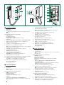
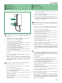
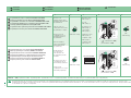
2719W - DESCRIZIONE
1. Altoparlante
2. Gancio fonica
Non avvicinare all’orecchio la cornetta con gancio fonica
premuto.
Pulsanti pre-programmati [programmabili]
PKEY Apriporta
P1 Attuatore generico
P2 Chiamata a centralino
P3 Chiamata a centralino principale / Dottore
P4 Allarme
3. LED rosso (DOTTORE / OCCUPATO / IN PROGRAMMAZIONE)
Funzione Dottore: Apertura automatica della porta su
chiamata da posto esterno.
4. Selettore suoneria/modalità Privacy a 3 posizioni
5. Indicatore rosso: modalità Privacy attiva
Suoneria in modalità silenziosa alla ricezione di una chiamata
da posto esterno e da centralino.
6. JP1 JP2 Jumpers per liberare pulsante 4 (Pag. 12)
7. Morsettiera M2 Pulsante 4:
C4 P4 per servizi vari (Pag. 12)
8. Morsettiera M1 Connessione impianto:
L L Connessione alla linea BUS
CFP CFP Ingresso chiamata da piano (Pag. 12)
9. JP3 Jumper per la chiusura video
10. S1 Micro-interruttori per impostazione codice utente e pulsanti
11. SW2 Selettore per definire la tipologia di impianto:
SimpleBus 1 (S1), SimpleBus 2 (S2) (Pag. 11)
12. PR Jumper per programmazione pulsanti e funzioni
A Funzioni programmate
B In programmazione
2719W - DESCRIPTION
1. Haut-parleur
2. Crochet phonie
Ne pas approcher le combiné de l’oreille si le crochet phonie
est enclenché.
Boutons déjà programmés [programmables]
PKEY Ouvre-porte
P1 Actionneur générique
P2 Appel au standard
P3 Appel au standard principal / Ouverture automatique
P4 Alarme
3. LED rouge (OUVERTURE AUTOMATIQUE / OCCUPÉ /
PROGRAMMATION)
Ouverture automatique : Ouverture automatique de la porte
sur appel provenant d’une platine extérieure.
4. Sélecteur sonnerie/modalité Privacy à 3 positions
5. Indicateur rouge : modalité Privacy actif
La sonnerie passe en mode silencieux lors d’un appel
provenant de la platine extérieure et du standard.
6. JP1 JP2 Cavalier pour libérer le bouton 4 (Page 12)
7. Bornier M2 bouton 4 :
C4 P4 pour services divers (Page 12)
Bornier M1 connexion à l’installation :
L L Connexion à la ligne BUS
CFP CFP Entrée de l’appel porte palière (Page 12 )
8. JP3 Cavalier pour désactiver le signal vidéo
9. S1 Micro-interrupteurs pour saisie code usager et boutons
10. SW2 Sélecteur pour modifier le type d’installation :
SimpleBus 1 (S1), SimpleBus 2 (S2) (Page 11)
2719W - DESCRIPTION
1. Loudspeaker
2. Audio hook
Do not bring the handset to your ear while the audio hook is
pressed down.
Pre-programmed buttons [programmable]
PKEY Lock-release button
P1 Generic actuator
P2 Call to switchboard
P3 Call to main switchboard / Doctor
P4 Alarm
3. Indicator LED (DOCTOR/BUSY/PROGRAMMING)
Doctor function: Automatic door opening on receipt of call
from external unit.
4. 3-position selector for Call tone/Privacy mode
5. Red indicator: Privacy enabled
The ringtone will be silenced on receipt of a call from the
external unit and from the switchboard.
6. JP1 JP2 Jumpers for freeing button P4 (Page 12)
7. Terminal block M2 - Button 4:
C4 P4 for various services (Page 12)
8. Terminal block M1 for system connection:
L L BUS line connection
CFP CFP Outside door call input (Page 12)
9. JP3 Jumper to close the video signal
10. S1 Micro-switches for setting user code and buttons
11. SW2 To select the system type:
SimpleBus 1 (S1), SimpleBus 2 (S2) (Page 11)
12. PR Jumper for programming keys and functions
A Programmed functions
B In programming
La pagina si sta caricando...

4
1
2
1
2
2
2
1
1
3
3
2
1
1
3
3
2D2C2B
S1
SW1
JP1
CFP
CFP
L
L
S1
SW1
JP1
CFP
CFP
L
L
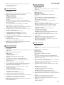
max 7 cm
1
1
CLACK!
2
CLACK!
1
1
1
1
2
543
1
cm 160
cm 130
2
2
1
2
2
3
2A
1
mm 190
mm 105
6
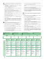
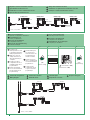
Installazione a parete
Installation
Montage en saillie
Installatiemodus
Aufputzmontage
Instalación de pared
Instalação de parede

5
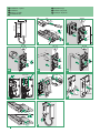
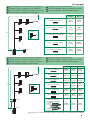
L’operazione è possibile solo con l’impianto in situazione di
riposo, in caso contrario il LED di segnalazione lampeggerà per
avvisare l’utente.
1. Tenere premuto (> 5 sec) il pulsante PKEY A fino a che non
verrà emesso un suono. Il LED lampeggia.
2. Premere e rilasciare il pulsante PKEY A
• 1 volta (viene emesso un tono di conferma) per modificare la
suoneria di chiamata da posto esterno
• 2 volte (vengono emessi 2 toni di conferma) per modificare la
suoneria di chiamata da centralino
• 3 volte (vengono emessi 3 toni di conferma) per modificare la
suoneria della chiamata intercomunicante
• 4 volte (vengono emessi 4 toni di conferma) per modificare la
suoneria della chiamata fuori porta
» Ulteriori pressioni del pulsante ripetono la sequenza appena
descritta.
3. Premere e rilasciare il pulsante P1 per scorrere in sequenza le
varie suonerie disponibili.
4. Premere e rilasciare il pulsante P2 per confermare la scelta
dell’ultima suoneria ascoltata e per uscire (in qualunque
momento) dalla modalità di variazione suoneria. All’uscita
dalla modalità di variazione suoneria verrà emesso un suono
di conferma.
This operation is only possible with the system in standby mode;
otherwise the LED indicator will flash to warn the user.
1. Press and hold ( >5 sec) A PKEY button until a confirmation
tone sounds. LED flashes.
2. Press and release the A PKEY button
• Once: (1 confirmation tone is emitted) to change the ringtone of
a call from the external unit
• 2 times: (2 confirmation tones are emitted) to change the
switchboard call ringtone
• 3 times: (3 confirmation tones are emitted) to change the
intercom call ringtone
• 4 times: (4 confirmation tones are emitted) to change the floor
door call ringtone
Cette opération n’est possible que lorsque l’installation est en
condition de repos; dans le cas contraire, la LED de signalisation
clignote pour avertir l’utilisateur.
1. Maintenir (> 5 sec) le bouton PKEY A appuyé jusqu’à ce
qu’une tonalité de confirmation soit audible. La LED clignote.
2. Appuyer et relâcher le bouton PKEY A
• 1 fois (émission d’une tonalité de confirmation) pour modifier la
sonnerie d’appel depuis le poste extérieur
• 2 fois (émission de 2 tonalités de confirmation) pour modifier la
sonnerie d’appel depuis standard
• 3 fois (émission de 3 tonalités de confirmation) pour modifier la
sonnerie d’appel intercommunicant
• 4 fois (émission de 4 tonalités de confirmation) pour modifier la
sonnerie d’appel porte palière
» Appuyer ultérieurement sur le bouton pour répéter en
séquence les opérations décrites ci-dessus.
3. Appuyer et relâcher le bouton P1 pour écouter les diverses
sonneries disponibles l’une après l’autre.
4. Appuyer et relâcher le bouton P2 pour confirmer le choix de
la sonnerie choisie et pour sortir (à n’importe quel moment) de
la modalité de variation sonnerie. Une tonalité de confirmation
vous avertira que vous avez quitté la modalité de variation de
la sonnerie.
1. Houd de drukknop A PKEY ingedrukt tot u een bevestigingstoon
hoort (dit is alleen mogelijk wanneer de installatie in de ruststand
verkeert; wanneer dit niet het geval is, knippert de led om de
gebruiker te waarschuwen).
» LED knippert
2. Druk vervolgens op de knop A PKEY en laat hem weer los:
• 1 maal (er klinkt één enkele bevestigingstoon) om de beltoon
van een oproep vanaf het entreepaneel te wijzigen
• 2 maal (er klinken 2 bevestigingstonen) om de beltoon van een
oproep vanaf de portierscentrale te wijzigen
• 3 maal (er klinken 3 bevestigingstonen) om de beltoon van een
intercomoproep te wijzigen
• 4 maal (er klinken 4 bevestigingstonen) om de beltoon van een
oproep van de etagebel te wijzigen
» Wanneer u nog vaker op de knop A PKEY drukt, wordt de
bovenstaande volgorde herhaald.
3. Druk op de knop P1 en laat hem weer los om de beschikbare
beltonen op volgorde te beluisteren.
4. Druk op de knop P2 hem terug om uw keuze van de laatste
beluisterde beltoon te bevestigen en de modus Wijzigen beltoon
van de deurtelefoon (op ieder gewenst moment) te verlaten.
Wanneer u de modus Wijzigen beltoon van deurtelefoon verlaat,
klinkt er een bevestigingstoon.
P2
LED
P1
PKEY
» Any further pressing of the PKEY button repeats the
sequence described above.
3. Press and release the P1 button to scroll through the various
ringtones available in sequence.
4. Press and release the P2 button to confirm selection of
the last ringtone heard and to exit the ringtone selection
mode (at any time). On exiting the ringtone selection mode a
confirmation tone will be emitted.
Variazione suonerie
Changing Call tones
Programmation sonneries
Wijzigen beltoon
Tonveränderung
Variación de los tonos
Variações das campainhas
La pagina si sta caricando...

7
Codice /
Code
DIP-Switch
ON
S1
1 1
2 2
3 3
4 4
5 5
6
6
7 7
8
8
Codice
/ Code
DIP-Switch
ON
1 1
31
1,2,3,4,5
61
1,3,4,5,6
91
1,2,4,5,7
121
1,4,5,6,7
151
1,2,3,5,8
181
1,3,5,6,8
211
1,2,5,7,8
2
2 32 6 62 2,3,4,5,6 92 3,4,5,7 122 2,4,5,6,7 152 4,5,8 182 2,3,5,6,8 212 3,5,7,8
3 1,2 33 1,6 63 1,2,3,4,5,6 93 1,3,4,5,7 123 1,2,4,5,6,7 153 1,4,5,8 183 1,2,3,5,6,8 213 1,3,5,7,8
4 3 34 2,6 64 7 94 2,3,4,5,7 124 3,4,5,6,7 154 2,4,5,8 184 4,5,6,8 214 2,3,5,7,8
5 1,3 35 1,2,6 65 1,7 95 1,2,3,4,5,7 125 1,3,4,5,6,7 155 1,2,4,5,8 185 1,4,5,6,8 215 1,2,3,5,7,8
6 2,3 36 3,6 66 2,7 96 6,7 126 2,3,4,5,6,7 156 3,4,5,8 186 2,4,5,6,8 216 4,5,7,8
7 1,2,3 37 1,3,6 67 1,2,7 97 1,6,7 127 1,2,3,4,5,6,7 157 1,3,4,5,8 187 1,2,4,5,6,8 217 1,4,5,7,8
8 4 38 2,3,6 68 3,7 98 2,6,7 128 8 158 2,3,4,5,8 188 3,4,5,6,8 218 2,4,5,7,8
9 1,4 39 1,2,3,6 69 1,3,7 99 1,2,6,7 129 1,8 159 1,2,3,4,5,8 189 1,3,4,5,6,8 219 1,2,4,5,7,8
10 2,4 40 4,6 70 2,3,7 100 3,6,7 130 2,8 160 6,8 190 2,3,4,5,6,8 220 3,4,5,7,8
11 1,2,4 41 1,4,6 71 1,2,3,7 101 1,3,6,7 131 1,2,8 161 1,6,8 191 1,2,3,4,5,6,8 221 1,3,4,5,7,8
12 3,4 42 2,4,6 72 4,7 102 2,3,6,7 132 3,8 162 2,6,8 192 7,8 222 2,3,4,5,7,8
13 1,3,4 43 1,2,4,6 73 1,4,7 103 1,2,3,6,7 133 1,3,8 163 1,2,6,8 193 1,7,8 223 1,2,3,4,5,7,8
14 2,3,4 44 3,4,6 74 2,4,7 104 4,6,7 134 2,3,8 164 3,6,8 194 2,7,8 224 6,7,8
15 1,2,3,4 45 1,3,4,6 75 1,2,4,7 105 1,4,6,7 135 1,2,3,8 165 1,3,6,8 195 1,2,7,8 225 1,6,7,8
16 5 46 2,3,4,6 76 3,4,7 106 2,4,6,7 136 4,8 166 2,3,6,8 196 3,7,8 226 2,6,7,8
17 1,5 47 1,2,3,4,6 77 1,3,4,7 107 1,2,4,6,7 137 1,4,8 167 1,2,3,6,8 197 1,3,7,8 227 1,2,6,7,8
18 2,5 48 5,6 78 2,3,4,7 108 3,4,6,7 138 2,4,8 168 4,6,8 198 2,3,7,8 228 3,6,7,8
19 1,2,5 49 1,5,6 79 1,2,3,4,7 109 1,3,4,6,7 139 1,2,4,8 169 1,4,6,8 199 1,2,3,7,8 229 1,3,6,7,8
20 3,5 50 2,5,6 80 5,7 110 2,3,4,6,7 140 3,4,8 170 2,4,6,8 200 4,7,8 230 2,3,6,7,8
21 1,3,5 51 1,2,5,6 81 1,5,7 111 1,2,3,4,6,7 141 1,3,4,8 171 1,2,4,6,8 201 1,4,7,8 231 1,2,3,6,7,8
22 2,3,5 52 3,5,6 82 2,5,7 112 5,67 142 2,3,4,8 172 3,4,6,8 202 2,4,7,8 232 4,6,7,8
23 1,2,3,5 53 1,3,5,6 83 1,2,5,7 113 1,5,6,7 143
1,2,3,4,8
173 1,3,4,6,8 203 1,2,4,7,8 233 1,4,6,7,8
24 4,5 54 2,3,5,6 84 3,5,7 114 2,5,6,7 144
5,8
174 2,3,4,6,8 204 3,4,7,8 234 2,4,6,7,8
25 1,4,5 55 1,2,3,5,6 85 1,3,5,7 115 1,2,5,6,7 145 1,5,8 175 1,2,3,4,6,8 205 1,3,4,7,8 235 1,2,4,6,7,8
26 2,4,5 56 4,5,6 86 2,3,5,7 116 3,5,6,7 146 2,5,8 176 5,6,8 206 2,3,4,7,8 236 3,4,6,7,8
27 1,2,4,5 57 1,4,5,6 87 1,2,3,5,7 117 1,3,5,6,7 147 1,2,5,8 177 1,5,6,8 207 1,2,3,4,7,8 237 1,3,4,6,7,8
28 3,4,5 58 2,4,5,6 88 4,5,7 118 2,3,5,6,7 148 3,5,8 178 2,5,6,8 208 5,7,8 238 2,3,4,6,7,8
29 1,3,4,5 59 1,2,4,5,6 89 1,4,5,7 119 1,2,3,5,6,7 149 1,3,5,8 179 1,2,5,6,8 209 1,5,7,8 239 1,2,3,4,6,7,8
30 2,3,4,5 60 3,4,5,6 90 2,4,5,7 120 4,5,6,7 150 2,3,5,8 180 3,5,6,8 210 2,5,7,8 *240 5,6,7,8
TAB. A
TAB. B
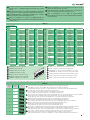
Tabella di programmazione codici utente/chiamata intercomunicante
generale (TAB. A) e indirizzo/chiamata intercomunicante selettiva
(TAB. B)
ESEMPIO impostazione codice 200
É necessario impostare l'indirizzo intercomunicante a tutti i posti interni del montante.
É possibile associare lo stesso indirizzo intercomunicante a un max di 3 posti interni.
Per la chiamata di gruppo selezionare contemporaneamente i codici intercomunicanti desiderati (max 3).
*NOTA: il codice 240 è riservato per il centralino di portineria
Table for programming user codes/general intercom call (TAB. A) and
address/selective intercom call (TAB. B)
EXAMPLE setting code 200
You must set the intercom address on all the riser’s internal units.
You can assign the same intercom address to a maximum of 3 internal units.
For group calls, select the desired intercom codes simultaneously (max. 3).
*NOTE: code 240 is reserved for the porter switchboard
Table de programmation des codes utilisateur/appel intercommunicant
général (TAB. A) et adresse/appel intercommunicant sélectif (TAB. B)
EXEMPLE introduction code 200
*REMARQUE: le code 240 est réservé au standard de conciergerie
Il est nécessaire de programmer l'adresse intercommunicante sur tous les postes intérieurs de la colonne montante.
Il est possible d'associer la même adresse intercommunicante à 3 postes intérieurs maximum.
Pour un appel de groupe sélectionner simultanément les codes intercommunicants voulus(max 3).
Programmeringstabel gebruikerscodes/algemene intercomoproep
(TAB. A) en adres/selectieve intercomoproep (TAB. B)
VOORBEELD instelling code 200
*OPMERKING: de code 240 is gereserveerd voor de portierscentrale
Het intercomadres moet bij alle binnentoestellen van de stamleiding worden ingesteld.
Het is mogelijk om hetzelfde intercomadres aan max. 3 binnentoestellen te koppelen.
Voor de groepsoproep moeten de gewenste intercomcodes tegelijkertijd worden geselecteerd (max. 3).
Programmierungstabelle Teilnehmercodes/Allgemeiner Internruf
(TAB. A) und Adresse/selektiver Internruf (TAB. B)
BEISPIEL: Einstellung von Teilnehmercode 200
*HINWEIS: Teilnehmercode 240 ist für die Pförtnerzentrale reserviert
Die Intercom-Adresse muss an allen Innensprechstellen der Steigleitung eingerichtet werden.
Dieselbe Intercom-Adresse kann maximal 3 Innensprechstellen zugeordnet werden.
Für den Gruppenruf die gewünschten Intercom-Codes gleichzeitig wählen (max. 3).
Tabla de programación de los códigos de usuario /llamada
intercomunicante general (TABLA A) y dirección/llamada intercomunicante
selectiva (TABLA B)
*NOTA: el código 240 está reservado a la centralita de conserjería
EJEMPLO: configuración del código 200
Es necesario configurar la dirección intercomunicante en todas las unidades internas de la columna montante.
Es posible asociar la misma dirección intercomunicante a un máximo de tres unidades internas.
Para la llamadaa de grupo, seleccionar simultáneamente los códigos intercomunicantes deseados (máximo 3).
Tabela de programação dos códigos de utilizador/chamada de
intercomunicação geral (TAB. A) e endereço/chamada de intercomunicação
selectiva (TAB. B)
*NOTA: o código 240 está reservado para a central de portaria
EXEMPLO configuração do código 200
É necessário configurar o endereço de intercomunicação em todos os postos internos da coluna.
É possível associar o mesmo endereço de intercomunicação a um máx. de 3 postos internos.
Para a chamada de grupo, seleccionar em simultâneo os códigos de intercomunicação desejados (máx. 3).

8
1. 2. 3. 4. 5.
B
A
PR
PR
(LED flashes
slowly)
PKEY
(4 fast flashes = OK)
(8 fast flashes = KO)
B
A
PR
PR
(LED
STOP flashing)
B
A
PR
PR
(LED flashes
slowly)
DIP-SWITCHES OFF
PKEY
(4 fast flashes = OK)
(8 fast flashes = KO)
B
A
PR
PR
(LED
STOP flashing)
B
A
PR
PR
(LED flashes
slowly)
/ P1
/ P2
/ P3
/ P4
4 Sec
(4 fast flashes = OK)
(8 fast flashes = KO)
B
A
PR
PR
(LED
STOP flashing)
8 FLASH ⇒ KO (Programmazione fallita - Programming failed - Programmation échouée - Programmering mislukt - Programmierung fehlgeschlagen - Programación fallida - Erro na programação)
INTERCOMUNICANTE
INTERCOM
INTERCOMMUNICANT
INTERCOM
INTERNGESPRÄCH
INTERCOMUNICANTE
INTERCOMUNICAÇÃO
Cancelar endereço de intercomunicação
Cancellare Indirizzo intercomunicante
Deleting the intercom address
Effacer adresse intercommunicant
Intercomadres wissen
Löschung der Intercom-Adresse
Borrado de la dirección intercomunicante
impostare codice, TAB. B pag. 7
set code, TAB. B on page 7
programmer code, TAB. B page 7
code instellen, TAB. B op pag. 7
eingabe des Codes, TAB. B seite 7
configurar código, TAB. B de pág. 7
configurar código, TAB. B na pág. 7
impostare codice, pag. 7:
TAB. A* per intercomunicante generale
TAB. B per intercomunicante selettivo
set code, page 7:
TAB. A* for general intercom
TAB. B for selective intercom
programmer code, page 7 :
TAB. A* pour intercommunicant général
TAB. B pour intercommunicant sélectif
code instellen, pag. 7:
TAB. A* voor algemene intercom
TAB. B voor selectieve intercom
Code einstellen, Seite 7:
TAB. A* für allgemeinen Internruf
TAB. B für selektiven Internruf
configurar código, pág. 7:
TABLA A* para intercomunicante general
TABLA B para intercomunicante selectiva
configurar código, pág. 7:
TAB. A* para chamada de intercomunicação
geral
TAB. B para chamada de intercomunicação
selectiva
Prendere nota
dell'impostazione di S1 e
ripristinarla al termine della
programmazione
Assegnare Indirizzo intercomunicante
(Solo per chiamata intercom. selettiva)
Take note of the S1
setting and restore it when
programming is complete
To assign Intercom address (for selective intercom call only)
Prendre note de la
configuration de S1 et
la rétablir à la fin de la
programmation
Attribuer adresse intercom. (uniquement pour appel intercomm.sélectif)
Noteer de instelling
van S1 en herstel deze
aan het einde van de
programmering
Intercomadres (alleen voor selectieve intercomoproep)
Die Einstellung von
S1 notieren und
nach Abschluss der
Programmierung wieder
herstellen
Intercom-Adresse (nur für selektiven Internruf)
Anotar la posición de S1
y restablecerla una vez
efectuada la programación
Asignar dirección intercomunicante (solo para llamada intercom. selectiva)
Tomar nota da
configuração de S1 e repor
no final da programação
Introduzir endereço de intercomunicação
(Para chamada de intercom. selectiva)
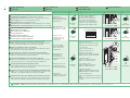
Programmazione tasti per chiamata intercomunicante (P1-P4)
TAB. A* Lasciando impostato il codice utente del posto interno chiamante,
viene programmata la chiamata intercomunicante monofamiliare.
Buttons programming for intercom call (P1-P4)
TAB. A* By leaving the user code set for the internal unit making the call, the
single-family intercom call will be programmed.
Programmation des boutons pour appel intercommunicant (P1-P4)
TAB. A* En laissant configuré le code usager du poste intérieur appelant,
l'appel intercommunicant un usager est programmé.
Programmering drukknoppen voor intercomoproep (P1-P4)
TAB. A* Door de gebruikerscode van de interne aansluiting ingesteld te laten,
wordt de intercomoproep voor ééngezinswoningen geprogrammeerd.
Tastenprogrammierung für Interngespräch (P1-P4)
TAB. A* Wird der Teilnehmercode der anrufenden Innensprechstelle gelassen,
wird der Einfamilienhaus-Internruf programmiert.
Programación de los pulsadores para llamada intercomunicante (P1-P4)
TABLA A* Si el código de usuario de la unidad interna que llama se deja
configurado, se programa la llamada intercomunicante unifamiliar.
Programação dos botões para chamadas de intercomunicação (P1-P4)
TAB. A* Ao deixar configurado o código de utilizador do posto interno emissor
da chamada, é programada a chamada de intercomunicação monofamiliar.

9
1. 2. 3. 4. 5.
B
A
PR
PR
(LED flashes slowly)
/ P1
/ P2
/ P3
/ P4
4 Sec
( + 4 fast flashes = OK)
( 8 fast flashes = KO)
B
A
PR
PR
(LED
STOP flashing)
B
A
PR
PR
(LED flashes slowly)
DIP-SWITCHES ON
/ P1
/ P2
/ P3
/ P4
4 Sec
( + 4 fast flashes = OK)
( 8 fast flashes = KO)
B
A
PR
PR
(LED
STOP flashing)
8 FLASH ⇒ KO (Programmazione fallita - Programming failed - Programmation échouée - Programmering mislukt - Programmierung fehlgeschlagen - Programación fallida - Erro na programação)
Non avvicinare all’orecchio la cornetta con gancio fonica premuto. - Do not bring the handset to your ear while the audio hook is pressed down. - Ne pas approcher le combiné de l’oreille si le crochet phonie est enclenché. - Met
ingedrukte telefoonhaak uw oor niet bij de hoorn houden. - Den Hörer bei gedrückter Gabel der Sprechgarnitur nicht dem Ohr annähern. - No acercar el microteléfono al oído con el gancho de audio presionado. - Não aproximar a orelha
ao auscultador com o gancho do som premido.
Programmazione tasti per comando ATTUATORE CON CODICE
Programmazione tasto per comando ATTUATORE GENERICO
ATTUATORI
Buttons programming for controlling ACTUATOR WITH CODE
Button programming for controlling GENERIC ACTUATOR
ACTUATORS
Programmation bouton de commande ACTIONNEUR GÉNÉRIQUE
Programmation des boutons de commande ACTIONNEUR AVEC CODE
ACTIONNEURS
Programmering drukknop voor bediening algemene relaissturing
Programmering drukknoppen voor bediening relaissturing MET CODE
RELAISSTURINGEN
Programmierung der Taste für allgemeine Relaissteuerung
Tastenprogrammierung für Relaissteuerung MIT CODE
RELAIS-FUNKTIONEN
Programación pulsador para mando de ACTUADOR GENÉRICO
Programación de los pulsadores para mando de ACTUADOR CON CÓDIGO
ACTUADORES
Programação dos botões para comando ACTUADOR COM CÓDIGO
Programação botão para comando ACTUADOR GERAL
impostare codice,
TAB. A (Pag. 7)
set code,
TAB. A (Page 7)
programmer code,
TAB. A (Page 7)
code instellen,
TAB. A (Pag. 7)
eingabe des Codes,
TAB. A (Seite 7)
configurar código,
TAB. A (Pág. 7)
configurar código,
TAB. A (Pág. 7)
ACTUADORES
Prendere nota
dell'impostazione di S1 e
ripristinarla al termine della
programmazione
Take note of the S1
setting and restore it when
programming is complete
Prendre note de la
configuration de S1 et
la rétablir à la fin de la
programmation
Noteer de instelling
van S1 en herstel deze
aan het einde van de
programmering
Die Einstellung von
S1 notieren und
nach Abschluss der
Programmierung wieder
herstellen
Anotar la posición de S1
y restablecerla una vez
efectuada la programación
Tomar nota da
configuração de S1 e repor
no final da programação

10
INTERCOM: 1 INTERCOM: 2 INTERCOM: 3 INTERCOM: 4
USER CODE: 1
USER CODE: 1
USER CODE: 1 USER CODE: 1
1 2 3 4 5 6
LM
LM
OUT
L
IN
L
IN
L
OUT
L
1214/2C 1214/2C
2719W
P
F
C
P
F
C
LL
CP
4 4
LM
LM
OUT
L
IN
L
IN
L
OUT
L
C
F
P
LL
C
F
P
1
2
C
F
P
LL
C
F
P
1
2
6741W 6721W
1209 / 1210 /4888C
ON
12345678
ON
12345678
ON
12345678
ON
12345678
CV5
6750W
C
F
P
LL
C
F
P
1
2
1. 2. 3. 4. 5.
B
A
PR
PR
(LED
flashes slowly)
DIP-SWITCHES ON
PKEY
( +4 fast flashes = OK)
(8 fast flashes = KO)
B
A
PR
PR
(LED
stop flashing)
LM
LM
OUT
L
IN
L
IN
L
OUT
L
1214/2C
1214/2C
2719W
P
F
C
P
F
C
LL
CP
4 4
LM
LM
OUT
L
IN
L
IN
L
OUT
L
C
F
P
LL
C
F
P
1
2
6721W
1209 / 1210 /4888C
ON
12345678
LM
LM
OUT
L
IN
L
IN
L
OUT
L
1214/2C
2719W
P
F
C
P
F
C
LL
CP
4 4
ON
12345678
ON
12345678
Ripristino configurazioni di fabbrica
Reset programmazione
Impianto con intercomunicante selettivo
Schema di collegamento
Factory configurations
System with selective intercom
Programming reset
Wiring diagram
Configurations d'usine
Installation avec intercommunicant sélectif
Reset de programmation
Schéma de connexion
Fabrieksinstellingen
Systeem met selectieve intercom
Reset van de programmering
Aansluitschema
Werkseitige Voreinstellungen
Anlage mit selektivem internruf
Reset de Programmierung
Anschlussplan
Configuraciones de fábrica
Instalación con aparato intercomunicante selectivo
Reset del la programación
Esquema de conexión
Reinicialização da programação
Prendere nota
dell'impostazione di S1
e ripristinarla al termine
della programmazione
Take note of the S1
setting and restore it
when programming is
complete
Prendre note de la
configuration de S1 et
la rétablir à la fin de la
programmation
Noteer de instelling
van S1 en herstel deze
aan het einde van de
programmering
Die Einstellung von
S1 notieren und
nach Abschluss der
Programmierung
wieder herstellen
Anotar la posición
de S1 y restablecerla
una vez efectuada la
programación
Tomar nota da
configuração de S1
e repor no final da
programação
Configurações de fábrica
Instalação com intercomunicador selectivo
Esquema de ligação

11
B
1622
A
1595
SW2
S1
2719W
N° 4 MAX
A MAX B MAX
1 mm² (Ø 1,2 mm AWG 17)
50 m
(165 feet)
500 m
(1625 feet)
0,28 mm² (Ø 0,6 mm AWG 23)
5 m
(15 feet)
300 m
(990 feet)
0,5 mm² (Ø 0,8 mm AWG 20)
25 m
(85 feet)
400 m
(1315 feet)
1,5 mm² (Ø 1,4 mm AWG 15)
75 m
(245 feet)
600 m
(1980 feet)
2,5 mm² (Ø 1,8 mm AWG 13)
100 m
(330 feet)
800 m
(2600 feet)
A
B
C
1210
1621
2719W
SW2
S2
N° 4 MAX
A MAX B MAX C MAX
Comelit Art. 4577/4579 1 mm²
(Ø 1,2 mm AWG 17)
260 m
(850 feet)
130 m
(425 feet)
130 m
(425 feet)
UTP5 cat. 5 0,2 mm²
(Ø 0,5 mm AWG 24)
80 m
(260 feet)
40 m
(130 feet)
40 m
(130 feet)
0,28 mm²
(Ø 0,6 mm AWG 23)
100 m
(328 feet)
50 m
(164 feet)
50 m
(164 feet)
0,5 mm²
(Ø 0,8 mm AWG 20)
140 m
(460 feet)
70 m
(230 feet)
70 m
(230 feet)
1 mm²
(Ø 1,2 mm AWG 17)
200 m
(656 feet)
100 m
(328 feet)
100 m
(328 feet)
1,5 mm²
(Ø 1,4 mm AWG 15)
80 m
(260 feet)
40 m
(130 feet)
40 m
(130 feet)
UTP5 cat. 5 0,2 mm²
(Ø 0,5 mm AWG 24)
MULTI PAIR CABLE
GREEN
ORANGE
BLU
GREEN / WHITE
ORANGE / WHITE
BLU / WHITE
BROWN / WHITE
BROWN
260 m
(850 feet)
130 m
(425 feet)
130 m
(425 feet)
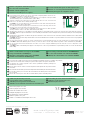
Cavo UTP con connessione multi-coppiola: RISPETTARE I COLORI INDICATI IN FIGURA!
Impianto SimpleBus 1: distanze massime di collegamento
Impianto SimpleBus 2: distanze massime di collegamento
SimpleBus 1 systems: maximum connection distances
SimpleBus 2 systems: maximum connection distances
Système SimpleBus 1 : Distances maximums de connexion
Système SimpleBus 2 : Distances maximums de connexion
Systeem SimpleBus 1: Maximale aansluitafstanden
Systeem SimpleBus 2: Maximale aansluitafstanden
SimpleBus 1-Anlage: Anschlussabstände
SimpleBus 2-Anlage: Anschlussabstände
Instalación SimpleBus 1: Distancias máximas de conexión
Instalación SimpleBus 2: Distancias máximas de conexión
Instalação SimpleBus 1: distância máxima da ligação
Instalação SimpleBus 2: distância máxima da ligação

P
F
C
LL
P
P C
4 4
F
C
CHIAMATA FUORIPORTA
*
P
F
C
LL
P
P C
4 4
F
C
JP1 JP2
NO C
24 V DC
100 mA max.
P
F
C
LL
P
P C
4 4
F
C
* 20 m max.
www.comelitgroup.com
Via Don Arrigoni, 5 - 24020 Rovetta (BG) - Italy
CERTIFIED MANAGEMENT SYSTEMS
1ª edizione 04/2018
cod. 2G40001793
In caso di più citofoni o monitor con lo stesso codice utente collegare il pulsante CFP su uno solo,
tutti i dispositivi suoneranno contemporaneamente.
* 20 m MAX - Utilizzare cavo schermato per il collegamento e non far passare i cavi in prossimità
di carichi induttivi pesanti o cavi di alimentazione (230V / 400V).
Rimuovere i jumper JP1 e JP2
Utilizzo del pulsante P4 per usi vari
La chiusura del contatto genera l'invio di una segnalazione di allarme generico al centralino di portineria.
Variante collegamento chiamata fuori porta
Utilizzo contatto P4/C4 come ingresso di ALLARME
If there are a number of door-entry phones or monitor with the same user code, connect the CFP
button to one only; all the devices will ring simultaneously.
* 20 m MAX - Use screened cable for the connection and do not run cables near heavy inductive
loads or power supply cables (230V / 400V).
Remove jumpers JP1 and JP2
Floor door call connection variant
Use for various services of button P4
Contact closure results in the sending of a generic alarm signal to the porter switchboard.
Using contact P4/C4 as ALARM input
En cas de plusieurs combinés parlophoniques ou moniteur avec le même code usager, relier le bouton
CFP sur un seul; tous les dispositifs sonneront en même temps.
* 20 m MAX - Pour la connexion, utiliser un câble blindé et ne pas faire passer les câbles à proximité
de charges inductives lourdes ou de câbles d’alimentation (230V / 400V).
Enlever les cavaliers JP1 et JP2
Variante connexion appel palier
Utilisation pour usages divers du bouton P4
La fermeture du contact engendre l'envoi d'une signalisation d'alarme générique au
standard de conciergerie.
Utilisation contact P4/C4 comme entrée d'ALARME
Sluit bij meerdere deurtelefoons of grondplaten met dezelfde gebruikerscode de drukknop CFP op slechts één ervan aan; alle toestellen gaan dan tegelijk over.
* 20 m MAX - Gebruik een afgeschermde kabel voor deze verbinding en leid de kabels niet in de nabijheid van hoge inductieve belastingen of netvoedingskabels
(230V/400V).
Verwijder de jumpers JP1 en JP2
Variant met aansluiting van een etagebel
Gebruik voor verschillende doeleinden van de drukknop P4
Bij het sluiten van het contact wordt een algemeen alarmsignaal naar de portierscentrale
verzonden.
Gebruik contact P4/C4 als ALARM-ingang
Im Fall mehrerer Sprechstellen oder Monitor mit gleichem Teilnehmercode die CFP-Taste nur an ein Gerät anschließen; daraufhin ertönt an allen Geräten
gleichzeitig der Rufton.
* 20 m MAX - Für den Anschluss abgeschirmte Kabel verwenden und die Kabel nicht in der Nähe von großen induktiven Lasten oder Stromversorgungskabeln
(230V /400V) verlegen.
Die Stecker JP1 und JP2 entfernen
Anschlussvariante Rufsignale der Außensprechstellen
Verwendung der Taste P4 für Zusatzfunktionen
Das Schließen des Kontakts generiert eine allgemeine Alarmmeldung an die Pförtnerzentrale.
Verwendung von Kontakt P4/C4 als ALARMEINGANG
En caso de varios telefonillos o monitor con el mismo código de usuario, conectar el pulsador CFP a uno sólo; todos los dispositivos se activarán al mismo tiempo
* 20 m MAX - Utilizar cable blindado para la conexión y no tender los cables cerca de cargas inductivas pesadas o cables de alimentación (230V/400V).
Quitar los puentes JP1 y JP2
Variante con conexión para llamada timbre de planta
Pulsador P4 para varios usos
El cierre del contacto provoca el envío de una señalización de alarma genérica a la centralita
de conserjería.
Uso del contacto P4/C4 como entrada de ALARMA
Variante para ligação da campainha externa
No caso de vários telefones intercomunicadores ou monitor com o mesmo código de utilizador, ligar o botão CFP num só; todos os dispositivos soarão
em simultâneo.
* 20 m MAX - Utilizar cabo blindado para a ligação e não fazer passar os cabos nas proximidades de cargas indutivas pesadas ou de cabos de alimentação
(230V / 400V).
Retirar os comutadores de derivação JP1 e JP2
Utilização o botão P4 para vários usos
Utilização do contacto P4/C4 como entrada de ALARME
O fecho do contacto gera o envio de um sinal de alarme geral à central de portaria.
-
 1
1
-
 2
2
-
 3
3
-
 4
4
-
 5
5
-
 6
6
-
 7
7
-
 8
8
-
 9
9
-
 10
10
-
 11
11
-
 12
12


Comelit 2719W Manuale del proprietario
- Categoria
- Impianti citofonici
- Tipo
- Manuale del proprietario
in altre lingue
- English: Comelit 2719W Owner's manual
- français: Comelit 2719W Le manuel du propriétaire
- español: Comelit 2719W El manual del propietario
- Deutsch: Comelit 2719W Bedienungsanleitung
- Nederlands: Comelit 2719W de handleiding
- português: Comelit 2719W Manual do proprietário
Documenti correlati
-
Comelit 8472MC Technical Manual
-
-
-
-
-
-
-
-
-
