
Zurn Industries, LLC | Wilkins
1747 Commerce Way, Paso Robles, CA U.S.A. 93446 Ph. 855-663-9876, Fax 805-238-5766
In Canada | Zurn Industries Limited
3544 Nashua Drive, Mississauga, Ontario L4V 1L2 Ph. 905-405-8272, Fax 905-405-1292
www.zurn.com
Rev. A
Date: 3/12
Document No. BF-475- 475V-212&3
Patent No. 5,913,331
Product No. Model 475-475V
Model 475/475V
Reduced Pressure Principle Assembly
Page 1 of 2
Application
Designed for installation on potable water lines to protect against
both backsiphonage and backpressure of contaminated water
into the potable water supply. Assembly shall provide protection
where a potential health hazard exists. The Model 475 is for ap-
plications requiring vertical flow up and vertical flow down. The
Model 475V is for applications requiring vertical flow up. Ideal
for use where lead-free* valves are required.
Standards Compliance
• ASSE® Listed 1013
• AWWA Compliant C511, and C550
• CSA® Certified
• IAPMO® Listed
• UL® Classified
• C-UL® Classified
• FM® Approved
• NYC MEA 468-99-M VOL 4
• Approved by the Foundation for Cross Connection
Control and Hydraulic Research at the University of
Southern California
• NSF® Listed-Standard 61, Annex G*
*(0.25% MAX. WEIGHTED AVERAGE LEAD CONTENT)
Materials
Main valve body Ductile Iron ASTM A 536 Grade 4
Access covers Ductile Iron ASTM A 536 Grade 4
Coatings FDA Approved fusion epoxy finish
Internals Stainless steel, 300 Series
NORYL™, NSF Listed
Fasteners Stainless Steel, 300 Series
Elastomers EPDM (FDA approved)
Buna Nitrile (FDA approved)
Polymers NORYL™, NSF Listed
Springs Stainless steel, 300 series
Sensing line Stainless steel, braided hose
Features
Sizes: 2 1/2", 3"
Maximum working water pressure 175 PSI
Maximum working water temperature 140°F
Hydrostatic test pressure 350 PSI
End connections (Grooved for steel pipe) AWWA C606-87
(Flanged) ANSI B16.1
Class 125
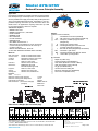
C
D
B
A
F
G
VENT
A
E
C
D
Dimensions & Weights (do not include pkg.)
Options
(Suffixes can be combined)
c - with NRS shut-off valves (standard)
c FS - with cast iron wye type strainer (flanged only)
c FSC - with epoxy coated wye type strainer
(flanged only)
c G - with groove end gate valves
c FG - with flanged inlet gate connection and
grooved outlet gate connection
c L - less shut-off valves (flanged body connections)
c OSY - with OS & Y gate valves
c MS - with Integral Relief Valve Monitor Switch
c V - vertical flow up configuration
Accessories
c
Repair kit (rubber only)
c
Thermal expansion tank (Model XT)
c
Valve setter (Model FLS or MJS or MJFS)
c
Gate valve tamper switch (OSY-40)
c
Air gap (Use Model AG-6)
c
QT-SET Quick Test Fitting Set
c
Electronic Solenoid Timer (Model EST)
c
Test Cock Lock (Model TCL24)

ഌ
Flow Characteristics
Zurn Industries, LLC
| Wilkins
1747 Commerce Way, Paso Robles, CA U.S.A. 93446 Ph. 855-663-9876, Fax 805-238-5766
In Canada | Zurn Industries Limited
3544 Nashua Drive, Mississauga, Ontario L4V 1L2 Ph. 905-405-8272, Fax 905-405-1292
www.zurn.com
Page 2 of 2
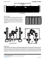
Typical Installation
Local codes shall govern installation requirements. To be in-
stalled in accordance with the manufacturers’ instructions and
the latest edition of the Uniform Plumbing Code. Unless other-
wise specified, the assembly shall be mounted at a minimum of
12" (305mm) and a maximum of 30" (762mm) above adequate
drains with sufficient side clearance for testing and maintenance.
The installation shall be made so that no part of the unit can be
submerged.
Speci cations
The Reduced Pressure Principle Backflow Preventer shall be ASSE® Listed 1013, and supplied with full port gate valves. The
main body and access covers shall be epoxy coated ductile iron (ASTM A 536 Grade 4), the seat ring and check valve shall be
NORYL™, the stem shall be stainless steel (ASTM A 276) and the seat disc elastomers shall be EPDM. Center stem guided design
shall incorporate two torsion springs to bias the check in the closed position. The first and second checks shall be accessible
for maintenance without removing the relief valve or the entire device from the line. If installed indoors, the installation shall be
supplied with an air gap adapter. The Reduced Pressure Principle Backflow Preventer shall be a WILKINS Model 475 or 475V.
SUPPORT
DIRECTION OF FLOW
PROTECTIVE
ENCLOSURE
DIRECTION OF FLOW
12" MIN.
30" MIN
-
 1
1
-
 2
2

