GCE AMBULANCE PANEL SYSTEM Istruzioni per l'uso
- Tipo
- Istruzioni per l'uso

GCE HEALTHCARE
INSTRUCTION FOR USE
NÁVOD K POUŽITÍ
ISTRUZIONI PER L‘USO
AMBULANCE PANEL SYSTEM EN
CS
AMBULANČNÍ PANELOVÝ SYSTÉM
SISTEMA DI PANNELLI PER AMBULANZE IT

2/20
EN
ENGLISH
INSTRUCTION FOR USE: AMBULANCE PANEL SYSTEM
1. FOREWORD
GCE Ambulance Panel System is a compatible package of medical
components which are, as a set, classified as class IIb according to the
Medical Device Directive 93/42/EEC.
Their Compliance with essential requirements of 93/42/EEC Medical
Device Directive is based upon EN 1789 standard.
2. INTENDED USE
GCE Ambulance Panel System (further referred to as “APS”) is a set
individual components that are to be assembled together according to the
drawing in Appendix Nr. 1.
APS is designed for use as an integral part of ambulance cars. APS always
consists of a pressure regulator to reduce the cylinder pressure, hoses and
terminal unit (Ambulance Panel II).
Components mentioned above may be supplied in various numbers and
optionally equipped with a manual, automatic switch and/or T-piece.
Assembly of the APS is described in the Appendix Nr. 1 and it is strictly
forbidden to change the given configuration.
APS is intended for administration of the following medical gases in the
treatment, management, diagnostic, evaluation and care of the patient:
• O2
• AIR
• Mixture of O2+N2O
APS are not intended for the driving of surgical tools.
Constructions, used materials and procedures of all APS components are
in compliance with EN 1789 standard and the basic requirements of
Appendix Nr. 1 of 93/42/EEC – MDD 2007/47/EC Medical Directive.
3. OPERATIONAL, TRANSPORT AND STORAGE
SAFETY REQUIREMENTS
Follow the instructions described in the Instructions for use dedicated to
single products.

3/20
EN
4. PRODUCT DESCRIPTION
APS is a set of components such as Pressure Regulators, Ambulance Pan-
els II, Hoses, and optionally changeover, that are supplied with their own
documentation.
For details about your set assembly please see the Appendix Nr. 1.
For details about each components, please refer to the Instruction for use
dedicated to each component. All sucient documents should be part of
this package.
Should you need any assistance, please contact your sales representative.
5. INSTALLATION
Installation must be performed according to the configuration given in
the Appendix Nr. 1. and in compliance with the EN 1789 standard.
Installation may be performed only by skilled technician and in compli-
ance with valid directives and standards.
5.1. TESTING BEFORE INSTALLATION
5.1.1. VISUAL CHECK BEFORE INSTALLATION
• Check if you have all components needed for the installation according
to Appendix Nr. 1.
• Check if there is not a visible external damage to the product (including
product labels and marking) and the gas passages are not contaminat-
ed. In case of any damage or contamination, contact the manufacturer.
• Check if the product service is not due or that the total life time of any
part the product and the gas cylinder has not been exceeded, (refer to
GCE or owner’s date coding system). If service or life time has been ex-
ceeded, remove the product (or the gas cylinder) from service & suitably
identify its status.
• Ensure that the product inlet stem of the regulator is compatible with the
medical cylinder valve (gas/ thread type).
• Check the presence & the integrity of inlet stem seals / correct size of
seal.
• Perform also a visual check according to the Instruction for use ded-
cated to each component.
5.2. INSTALLATION
• Assemble the individual components together according to the Appen-
dix Nr. 1. Use the prescribed tightening torques. Tightening torque of the
connection hoses nuts is 15 Nm.
It must be ensured that the connected gas cylinder is marked in a way
that the user qualified for gas cylinder exchange cannot exchange it for a
gas cylinder containing dierent type of gas.

4/20
EN
Use only suitable and functional tools and every time follow operational,
transport and storage safety requirements and cleanliness rules (see
chapter 3).
Never change the prescribed configuration and tightening torques.
5.3. TESTING AFTER INSTALLATION
• Perform all tests required by the documentation dedicated to single
products and required by the EN 1789 standard.
5.3.1. PERFORMANCE TEST
• Measure the outlet pressure directly at the outlet connection of the pres-
sure regulator while the flow at the terminal unit outlet connection is set
to 40l/min - see Appendix Nr. 1 - mark of TEST 1.
• Measure the outlet pressure at the terminal unit outlet furthermost probe
of the terminal unit (APII) while the flow at the terminal unit outlet con-
nection is set to 40l/min - see Appendix Nr. 1 - mark of TEST 2.
• Compare both parameters. If the dierence is not bigger than 10%, the
installation has been done correctly.
The test can only be performed when the cylinder is full.
Not performing the performance test may lead to the patient not being
supplied with the requested gas amount.
5.3.2. LEAKAGE TEST
• Check all connections using a leak detection fluid.
• If leakage is detected, follow according to the chapter ervice and Re-
pair.
6. OPERATION
6.1. CHECK BEFORE USE
• Visually check the pressure regulator(s), Ambulance Panel II(s),
changeover(s) for damage and/or contamination.
6.2. USE OF THE APS
• Follow the Instruction for use - Operation chapters of the dedicated
products (pressure regulator, Ambulance Panel II, etc.)
During the cylinder gas exchange, be aware that the gas for which the
APS is designated corresponds to the gas inside of the cylinder. Be extra
careful if there are more gases supply systems used in one ambulance.
Be aware that using a number of QC with an excessive gas consumption
at the same time may consequent to patient not being supplied with the
requested gas amount.

5/20
EN
6.3. AFTER USE
• Follow the Instruction for use - Operation chapter of the dedicated prod-
ucts (Pressure regulator, Ambulance Panel II)
7. CLEANING
Follow the cleaning procedure described in the Instructions for use dedi-
cated to individual products.
8. PRODUCT LIFETIME, MAINTENANCE, SERVICE
8.1. PRODUCT LIFETIME
Every component is equipped with its own serial and/or batch number.
Details can be found in the instruction for use dedicated to the individual
product.
SERIAL NUMBER AND DATE OF PRODUCTION OF THE APS
The complete assembly of APS is stamped on the Ambulance Panel II as
an eight-digit number YMPXXXMY:
Y - the last figure of the year
M - the first figure of the month
P - The code figure of the product
XXX - The numerical order of the product
M - The last figure of the month
Y - The third figure of the year
For example: Serial number 80612351 means a product manufactured in
May 2018 with product code figure 6 = Ambulance Panel, and 123 as a
numerical order of the product.
Note: The serial number of the APII and APS has got a significantly dier-
ent order and therefore it is easy to distinguish.
LIFE TIME
Product life time of the complete APS is 10 years from the date of manufac-
ture. At the end of the product’s life time, the product must be withdrawn
from the use. The owner shall put in place a relevant procedure to ensure
the product cannot be used again (marking,..).
WASTE MANAGEMENT
In accordance to Article 33 of REACH GCE, s.r.o. as a responsible manu-
facturer shall inform all customers if materials containing 0.1% or more of
substances included in the list of Substance of Very High Concern (SVHC).
The most commonly used brass alloys used for bodies and other brass
components contain 2-3% of lead (Pb), EC no. 231-468-6, CAS no. 7439-
92-1. The lead will not be released to the gas or surrounding environment
during normal use.

6/20
EN
After end of life the product shall be scrapped by an authorized metal re-
cycler to ensure ecient material handling with minimal impact to environ-
ment and health.
To date we have no information that indicates that other materials con-
taining SVHC of concentrations exceeding 0.1% are included in any GCE
product.
8.2. MAINTENANCE AND REPAIR
MAINTENANCE
• Perform the leak detection test and performance test described in the
chapter Testing after installation every two years.
• Perform the performance test
SERVICE AND REPAIR
The service and repairs shall be carried out by a GCE authorised person or
authorised service technician only.
Repair activities cover the replacement of the components of the APS. In-
dividual components are repaired in accordance to the Instruction for use
dedicated to the individual product.
Any product sent back to a GCE authorised person for maintenance shall
be properly packaged. The purpose of the maintenance has to be clearly
specified (repair, overall maintenance). For product to be repaired a short
description of fault and any reference to a claim number might be helpful.
All labels on the equipment must be kept in a good, legible condition by
the owner and user during the entire product life time.
All seals and o-rings must be kept in dry, dark and clean environment by
the owner and the user during the entire product life time.
Use only original GCE components!
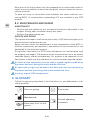
9. GLOSSARY
Follow the glossary described in the Instruction for use dedicated to indi-
vidual products.
Pressure gauge Flow-meter
Manufacturer
Consult operating
instruction
Keep away from oil and
grease

7/20
EN
APPENDIX:
Nr 1: Assembly scheme
MANUFACTURER:
GCE, s.r.o. Tel : +420 569 661 111
Zizkova 381 Fax : +420 569 661 602
583 01 Chotebor http://www.gcegroup.com
Czech Republic © GCE, s.r.o.
10. WARRANTY
The Standard Warranty period is two years from date of receipt by the GCE
Customer (or if this is not known 2 years from time of the product manufac-
ture shown on the product).
The standard warranty is only valid for products handled according to In-
struction for use (IFU) and general industry good practice and standards.

8/20
CS
ČESKY
NÁVOD K POUŽITÍ: AMBULANČNÍ PANELOVÝ SYSTÉM
1. PŘEDMLUVA
Ambulanční panelový systém společnosti GCE je kompatibilní balíček
zdravotnických prostředků, které tvoří soupravu, klasifikované jako třída
IIb podle směrnice 93/42/EHS o zdravotnických prostředcích.
Jejich soulad se základními požadavky směrnice 93/42/EHS o zdravotnick-
ých prostředcích je založen na normě EN ISO 1789.
2. ÚČEL POUŽITÍ
GCE Ambulanční Panelový Systém (dále označovaný jako „APS“) je soup-
rava jednotlivých prostředků, které se sestavují podle výkresu v Příloze č. 1.
Systém APS je navržen jako nedílná součást sanitních vozů. APS vždy
obsahuje regulátor tlaku pro regulaci tlaku v nádobě, hadice a terminální
jednotku (Ambulance Panel II).
Výše uvedené komponenty mohou být obsaženy v různém počtu a mohou
být volitelně vybaveny manuálním/automatickým spínačem nebo T-kusem.
Sestavení APS je popsáno v Příloze č. 1 a je přísně zakázáno měnit uve-
denou konfiguraci.
APS je určen k podávání následujících medicinálních plynů v rámci léčby,
managementu, diagnostiky, posouzení a péče o pacienta:
• O2
• Vzduch
• Směs O2+N2O
APS není určen k pohonu chirurgických nástrojů.
Konstrukce, použité materiály a postupy spojené s komponentami APS
splňují požadavky normy EN 1789 a zásadní požadavky Přílohy č. 1 Směrnic
93/42/EHS a 2007/47/ES o zdravotnických prostředcích.
3. POŽADAVKY NA PROVOZ, PŘEPRAVU A
BEZPEČNÉ SKLADOVÁNÍ
Postupujte podle pokynů uvedených v návodu k použití pro jednotlivé
produkty.
4. POPIS VÝROBKU
APS je souprava zdravotnických prostředků, jako jsou regulátory tlaku,
zařízení Ambulance Panel II, hadice a volitelné přepínače s vlastní doku-
mentací.
Podrobné pokyny k sestavení vaší soupravy naleznete v Příloze č. 1.

9/20
CS
Podrobné údaje o každé komponentě naleznete v Návodech k použití
jednotlivých prostředků. Všechny potřebné dokumenty by měly být
součástí tohoto balíčku.
Pokud budete potřebovat jakoukoliv podporu, obraťte se prosím na
Vašeho obchodního zástupce.
5. INSTALACE
Instalace musí být provedena v souladu s konfigurací uvedenou v
Příloze č. 1 a v souladu s normou EN 1789.
Instalaci mohou provádět pouze kvalifikovaní technici v souladu se
všemi platnými směrnicemi a normami.
5.1. TESTOVÁNÍ PŘED INSTALACÍ
5.1.1. VIZUÁLNÍ KONTROLA PŘED INSTALACÍ
• Zkontrolujte, zda máte díly potřebné pro instalaci podle Přílohy č. 1
• Zkontrolujte, zda neexistuje viditelné vnější poškození výrobku (včetně
štítků a označení výrobku) a zkontrolujte, že plynové cesty nejsou kon-
taminované. V případě kontaminace kontaktujte výrobce.
• Zkontrolujte, zda je třeba provést servis výrobku nebo zda nedošlo k
vypršení celkové životnosti nějaké části výrobku a tlakové lahve (viz
kódovací systém termínů společnosti GCE nebo vlastníka). Jestliže již
došlo k vypršení servisní lhůty nebo životnosti, vyřaďte výrobek (nebo
tlakovou lahev plynu) z provozu a náležitě stanovte stav příslušného
dílu.
• Ujistěte se, že vstupní přípojka regulátoru je slučitelný s ventilem tla-
kové lahve medicinálního plynu (plynový/závitový typ).
• Zkontrolujte přítomnost a neporušenost těsnění vstupní přípojky/
správnou velikost těsnění.
• Proveďte také vizuální kontrolu podle návodu k použití jednotlivých
komponent.
5.2. INSTALACE
• Sestavte jednotlivé komponenty podle Přílohy č. 1. Použijte předepsaný
utahovací moment. Utahovací moment matic připojovacích hadic je 15
Nm.
Musí být zajištěno, aby připojená plynová lahev byla označena tak, aby
ji uživatel kvalifikovaný pro výměnu plynové lahve nemohl zaměnit za
plynovou lahev obsahující jiný druh plynu.
Používejte pouze vhodné a funkční nástroje a vždy dodržujte provozní,
přepravní a skladovací bezpečnostní požadavky a pravidla čistoty (viz
kapitola 3).
Nikdy neměňte předepsanou konfiguraci a utahovací momenty.

10/20
CS
5.3. ZKOUŠENÍ PO INSTALACI
• Proveďte všechny zkoušky požadované v dokumentaci jednotlivých
produktů a požadované normou EN 1789.
5.3.1. ZKOUŠKA VÝKONU
• Změřte výstupní tlak přímo na výstupní přípojce regulátoru tlaku při
nastavení průtoku na výstupní přípojce terminální jednotky na 40 l / min
- viz Příloha č. 1 - značka TEST 1.
• Změřte výstupní tlak na nejvzdálenější sondě výstupu terminální jednot-
ky (APII) při nastavení průtoku na výstupní přípojce terminální jednotky
na 40 l / min - viz Příloha č. 1 - značka TEST 2.
• Porovnejte oba parametry. Pokud není rozdíl větší než 10 %,
byla instalace provedena správně.
Zkoušku lze provést pouze tehdy, když je nádoba plná.
Neprovedení zkoušky výkonu může vést k tomu, že pacientovi nebude
dodáno požadované množství plynu.
5.3.2. ZKOUŠKA TĚSNOSTI
• Zkontrolujte všechny přípojky pomocí kapaliny pro detekci netěsností.
• Pokud zjistíte únik, postupujte podle kapitoly Servis a Opravy.
6. PROVOZ
6.1. KONTROLA PŘED POUŽITÍM
• Vizuálně zkontrolujte regulátory tlaku, zařízení Ambulance Panel II,
přepínač(e) z hlediska poškození a kontaminace.
6.2. POUŽITÍ APS
• Postupujte podle kapitoly „Provoz“ v návodu k použití jednotlivých
zařízení (regulátor tlaku, Ambulance Panel II atd.)
Během výměny plynové lahve zkontrolujte, zda plyn v lahvi odpovídá
plynu, pro který je APS určen. Buďte zvlášť opatrní, pokud je v jedné
sanitce použito více plynových systémů.
Pamatujte, že použití více QC s nadměrnou spotřebou plynu současně
může mít za následek, že pacient nedostane požadované množství plynu.
6.3. PO POUŽITÍ
• Postupujte podle kapitoly „Provoz“ v návodu k použití jednotlivých
zařízení (regulátor tlaku, Ambulance Panel II).
7. ČIŠTĚNÍ
Postupujte podle postupu čištění popsaného v návodu k použití jednot-
livých produktů.

11/20
CS
8. ŽIVOTNOST, ÚDRŽBA A SERVIS VÝROBKU
8.1. ŽIVOTNOST VÝROBKU
Každá součást je vybavena vlastním číslem série nebo dávky. Podrobnosti
naleznete v návodu k použití jednotlivých produktů.
VÝROBNÍ ČÍSLO A DATUM VÝROBY VÝROBKU APS
Kompletní sestava APS je označena na zařízení Ambulance Panel II jako
osmiciferné číslo YMPXXXMY:
Y - poslední číslice roku
M - první číslice měsíce
P - Kód produktu
XXX - Numerické pořadí produktu
M - Poslední číslice měsíce
Y - Třetí číslice roku
Např. sériové číslo 80612351 znamená produkt vyrobený v květnu 2018 s
produktovým kódem 6 = Ambulance Panel s numerickým pořadím produk-
tu 123.
Poznámka: Sériová čísla APII a APS mají značně odlišnou strukturu, a
proto je lze snadno rozlišit.
ŽIVOTNOST
Maximální životnost výrobků je 10 let. Podrobnosti ohledně značení a
životnosti je možno nalézt v návodu k použití každého výrobku.
Na konci životnosti výrobku je nutné vyřadit výrobek z provozu. Vlastník
musí zavést příslušný postup pro zajištění toho, aby výrobek nebylo možno
znovu použít.
NAKLÁDÁNÍ S ODPADEM
V souladu s článkem 33 nařízení REACH se společnost GCE, s.r.o. jako
odpovědný výrobce zavazuje informovat všechny zákazníky, pokud mate-
riály obsahují 0,1 % nebo více látek uvedených na seznamu látek vzbuzují-
cích velmi velké obavy (SVHC).
Nejčastěji používané mosazné slitiny používané pro těla a další mosazné
komponenty obsahují 2 - 3 % olova (Pb), Č. ES 231-468-6, Č. CAS 7439-92-
1. Při normálním používání se olovo neuvolní do plynu ani do okolního pros-
tředí. Po skončení životnosti musí být výrobek zlikvidován autorizovanou
firmou pro recyklaci kovů, aby byla zajištěna účinná likvidace materiálu s
minimálním dopadem na životní prostředí a zdraví.
K dnešnímu dni nemáme žádné informace, které by naznačovaly, že v jaké-
mkoli produktu GCE jsou zahrnuty další materiály obsahující koncentrace
SVHC nad 0,1 %.

12/20
CS
8.2. ÚDRŽBA A OPRAVY
ÚDRŽBA
• Každé dva roky proveďte zkoušku těsnosti a zkoušku výkonu dle kapi-
toly Zkoušení po instalaci.
• Proveďte zkoušku výkonu.
SERVIS A OPRAVY
Servis a opravy budou prováděny pouze oprávněnými osobami společnosti
GCE nebo autorizovanými servisními techniky.
Činnosti v oblasti oprav pokrývají výměnu následujících poškozených
nebo chybějících komponentů APS.
Jednotlivé komponenty se opravují podle návodu k použití jednotlivých
komponent.
Jakýkoliv výrobek zaslaný zpět oprávněné osobě GCE pro účely údržby
musí být řádně zabalen. Je nutno jasně specifikovat účel údržby (oprava,
celková údržba). Aby bylo možno výrobek opravit, je vhodné uvést stručný
popis poruchy a odkaz na číslo reklamačního nároku.
Všechny štítky na zařízení musí být majitelem a uživatelem udržovány v
dobrém a čitelném stavu po celou dobu životnosti produktu.
Všechna těsnění a o-kroužky musí majitel a uživatel uchovávat v suchém,
tmavém a čistém prostředí po celou dobu životnosti produktu.
Používejte pouze původní komponenty GCE
9. SLOVNÍK
Postupujte podle pokynů uvedených v návodu k použití pro jednotlivé
produkty.
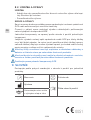
Manometr Průtokoměr
Výrobce
Čtěte návod k použití
Uchovávejte mimo místa
s výskytem oleje a tuku

13/20
CS
PŘÍLOHA:
Č. 1: Schéma sestavy
VÝROBCE:
GCE, s.r.o. Tel : +420 569 661 111
Žižkova 381 Fax : +420 569 661 602
583 01 Chotěboř http://www.gcegroup.com
Česká republika © GCE, s.r.o.
10. ZÁRUKA
Standardní záruční lhůta je dva roky od data obdržení zákazníkem
společnosti GCE (nebo pokud toto datum není známé, tak 2 roky od doby
vyrobení výrobku, jež je uvedena na výrobku).
Standardní záruční lhůta se vztahuje pouze na výrobky, s nimiž je
zacházeno podle návodu k použití (IFU) a v souladu s obecnými zásadami
a normami průmyslové praxe.

14/20
IT
ITALIANO
ISTRUZIONI PER L‘USO: SISTEMA DI PANNELLI PER
AMBULANZE
1. PREMESSA
Il sistema di pannelli per ambulanze GCE è un pacchetto compatibile di
component medici che, in qualità di insieme, sono classificati come classe
IIb in base alla direttiva sui dispositivi medici 93/42/CEE.
La loro conformità ai requisiti essenziali della direttiva 93/42/CEE sui dis-
positivi medici si basa sulla norma EN ISO 1789.
2. DESTINAZIONE D’USO
I sistemi di pannelli per ambulanze GCE (di seguito solo “SPA”) è un in-
sieme di singoli componenti che devono essere assemblati secondo il
disegno nell’appendice n. 1.
L’SPA è progettato per essere utilizzato come parte integrante di autoam-
bulanze. L’SPA è sempre costituito da un regolatore di pressione per ri-
durre la pressione della bombola, tubi flessibili e unità terminale (pannello
per ambulanze II).
I componenti sopra menzionati possono essere forniti in varie quantità e
opzionalmente dotati di un interruttore manuale, automatico e/o un rac-
cordo a T.
L’assemblaggio dell’SPA è descritto nell’appendice n. 1 ed è severamente
vietato cambiare la configurazione indicata.
L’SPA è destinato alla gestione dei seguenti gas medicali per il trattamento,
la gestione, la diagnostica, la valutazione e l’assistenza ai pazienti:
• O2
• ARIA
• Miscela di O2+N2O
L’SPA non è destinato alla gestione di strumenti chirurgici.
Le strutture, i materiali utilizzati e le procedure di tutti i componenti dell’SPA
sono conformi alla norma EN 1789 e ai requisiti di base dell’allegato n.
1 della direttiva sui dispositivi medici (DDM) 93/42/CEE e della direttiva
2007/47/CE
3. REQUISITI DI SICUREZZA PER LE OPERAZIONI, IL
TRASPORTO E LO STOCCAGGIO
Seguire le istruzioni descritte nei manuali dei singoli prodotti.

15/20
IT
4. DESCRIZIONE DEL PRODOTTO
L’SPA è un insieme di componenti quali regolatori di pressione, pannelli
per ambulanze II, tubi flessibili e, facoltativamente, interruttori, forniti con la
rispettiva documentazione.
Per i dettagli sul sistema assemblato, consultare l’appendice n. 1.
Per dettagli su ciascun componente, consultare le istruzioni per l’uso dedi-
cate a ciascun componente. Tutti i documenti sucienti dovrebbero far
parte di questo pacchetto.
Nel caso sia necessaria assistenza, contattare il rappresentante di vendita.
5. INSTALLAZIONE
L’installazione va eseguita secondo la configurazione di cui all’appendice
n. 1 e conformemente alla norma EN 1789.
L’installazione può essere eseguita solo da un tecnico specializzato e nel
rispetto di direttive e norme in vigore.
5.1. ANALISI PRIMA DELL’INSTALLAZIONE
5.1.1. CONTROLLO VISIVO PRIMA DELL’INSTALLAZIONE
• Controllare se si dispone delle parti necessarie per l’installazione in
base all’allegato n. 1
• Controllare se non ci sono danni visibili all’esterno del prodotto (tra cui
le etichette e la marcatura del prodotto) e le vie di passaggio del gas
non sono contaminate. In caso di danni o contaminazioni, contattare il
produttore.
• Controllare se il prodotto necessita di manutenzione o se è stato su-
perato il ciclo di vita completo di qualsiasi parte del prodotto e della
bombola di ga (fare riferimento a GCE o al sistema di codifica data del
proprietario). Se il periodo di manutenzione o il ciclo di vita è stato su-
perato, mettere fuori servizio il prodotto (o la bombola del gas) e identi-
ficarne opportunamente lo stato.
• Assicurarsi che la connessione di ingresso del regolatore sia compati-
bile con la valvola della bombola medicinale (tipo di gas/filettatura).
• Verificare la presenza e l’integrità delle guarnizioni della connessione di
ingresso /le dimensioni corrette della guarnizione.
• Eseguire inoltre un controllo visivo secondo le istruzioni per l’uso dedi-
cate di ciascun componente.
5.2. INSTALLAZIONE
• Montare i singoli componenti secondo l’appendice n. 1. Utilizzare le cop-
pie di serraggio prescritte. La coppia di serraggio dei dadi dei tubi flessi-
bili di collegamento è di 15 Nm

16/20
IT
È necessario assicurarsi che la bombola del gas collegata sia contrasseg-
nata in modo tale che l’utilizzatore qualificato per la sostituzione della
bombola del gas non possa sostituirla con una bombola del gas conte-
nente un tipo diverso di gas.
Usare solo attrezzi adatti e funzionanti e seguire sempre i requisiti di
sicurezza operativi, di trasporto e stoccaggio nonché le regole della puli-
zia (cfr. capitolo 3).
Non modificare mai la configurazione prescritta e le coppie di serraggio.
5.3. TEST DOPO L‘INSTALLAZIONE
• Eseguire tutti i test richiesti dalla documentazione dedicata dei singoli
prodotti e richiesti dalla norma EN 1789.
5.3.1. TEST DELLE PRESTAZIONI
• Misurare la pressione in uscita direttamente dalla connessione in uscita
del regolatore di pressione mentre la portata della connessione in uscita
dell’unità terminale è impostata su 40 l/min – cfr. appendice n. 1 – mar-
catura del TEST 1.
• Misurare la pressione in uscita della sonda più lontana dell’uscita
dell’unità terminale (APII) mentre la portata della connessione in uscita
dell’unità terminale è impostata su 40 l/min - cfr. appendice n. 1 – mar-
catura del TEST 2.
• Confrontare i due parametri. Se la dierenza non è superiore al 10%,
l’installazione è stata eseguita correttamente
Il test si può eseguire solo a bombola piena
La mancata esecuzione del test delle prestazioni può portare a fornire al
paziente una quantità di gas diversa da quella richiesta.
5.3.2. TEST DELLA TENUTA
• Controllare tutte le connessioni usando un fluido di rilevazione delle
perdite.
• Se si rileva una perdita, seguire le istruzioni del capitolo “Assistenza e
Riparazioni”.
6. FUNZIONAMENTO
6.1. CONTROLLO PRIMA DELL‘USO
• Controllare visivamente il/i regolatore/i di pressione, il/i pannello/i per
ambulanze II, l’interruttore/gli interruttori per verificare la presenza di
danni e/o contaminazioni.
6.2. USO DELL‘ APS
• Seguire le istruzioni per l’uso, capitolo “Operazioni” dei singoli prodotti

17/20
IT
(regolatore di pressione, pannello per ambulanze II, ecc.).
Durante la sostituzione del gas nella bombola, verificare che il gas
per cui è designato l’SPA corrisponda al gas all’interno della bombola.
Verificare attentamente se ci sono più sistemi di fornitura di gas usati
nell’ambulanza.
Tenere presente che l’utilizzo di un numero di QC con un consumo di gas
eccessivo allo stesso tempo può avere per conseguenza la fornitura al
paziente di una quantità di gas diversa da quella richiesta.
6.3. DOPO L‘USO
• Seguire le istruzioni per l’uso, capitolo “Operazioni” dei singoli prodotti
(regolatore di pressione, pannello per ambulanze II, ecc.).
7. PULIZIA
Seguire le procedure di pulizia descritte nel manuale dei singoli prodotti.
8. CICLO DI VITA DEL PRODOTTO,
MANUTENZIONE, ASSISTENZA
8.1. CICLO DI VITA DEL PRODOTTO
Ogni componente è dotato di numero di serie e/o di lotto. I dettagli sono
riportati nelle istruzioni per l’uso del singolo prodotto.
NUMERO DI SERIE DEL PRODOTTO E DATA DI PRODUZIONE APS
L’assemblaggio completo dell’SPA è stampato sul pannello per ambulanze
II come numero a otto cifre YMPXXXMY:
Y – ultima cifra dell’anno
M – prima cifra del mese
P – codice del prodotto
XXX – numero d’ordine del prodotto
M - ultima cifra del mese
Y – terza cifra dell’anno
Ad esempio, il numero di serie 80612351 indica che il prodotto è stato
fabbricato nel mese di maggio del 2018 con codice 6 = pannello per am-
bulanze e 123 come numero d’ordine del prodotto.
Nota: il numero di serie dell’APII e dell’SPA hanno numeri d’ordine molto
diversi e sono quindi facili da distinguere.
CICLO DI VITA
Il ciclo di vita massimo dei prodotti è di 10 anni. I dettagli di marcatura e cic-
lo di vita possono essere trovati nelle istruzioni per l’uso di ogni prodotto.
Alla fine del ciclo di vita del prodotto, esso deve essere messo fuori
servizio. Il proprietario deve seguire lna procedura rilevante per garantire
che il prodotto non possa essere riutilizzato.

18/20
IT
8.2. MANUTENZIONE E RIPARAZIONI
MANUTENZIONE
• Eseguire il test di rilevamento delle perdite e il test delle prestazioni
descritti nel capitolo Test dopo l’installazione ogni due anni.
• Eseguire il test delle prestazioni
ASSISTENZA E RIPARAZIONI
L’assistenza e le riparazioni sono eettuate solo da una persona autoriz-
zata GCE o da un tecnico di assistenza autorizzato.
Le attività di riparazione coprono la sostituzione dei seguenti componenti
danneggiati o mancanti APS.
I singoli componenti sono riparati secondo le istruzioni per l’uso rispettive.
Qualsiasi prodotto rispedito ad una persona autorizzata GCE per la ma-
nutenzione deve essere adeguatamente imballato. Lo scopo della ma-
nutenzione deve essere chiaramente specificato (riparazione, manuten-
zione generale). Per il prodotto da riparare può essere utile una breve
descrizione del guasto e qualsiasi riferimento ad un numero di reclamo
Tutte le etichette sull’apparecchiatura devono essere tenute in una buo-
na e leggibile condizione dal proprietario e utilizzatore durante l’intero
ciclo di vita del prodotto.
Tutti i sigilli e gli anelli a O devono essere tenuti in un ambiente asciutto,
buio e pulito dal proprietario e utilizzatore durante l’intero ciclo di vita
del prodotto.
Usare esclusivamente i ricambi GCE originali!
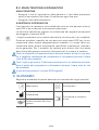
9. GLOSSARIO
Seguire le procedure di pulizia descritte nel manuale dei singoli prodotti.
Manometro Flussometro
Fabbricante
Consultare le istruzioni
d’uso
Tenere lontano da olio e
grasso

19/20
IT
ALLEGATO:
N. 1: Schema dell’assemblaggio
FABBRICANTE:
GCE, s.r.o. Tel : +420 569 661 111
Zizkova 381 Fax : +420 569 661 602
583 01 Chotebor http://www.gcegroup.com
Repubblica Ceca © GCE, s.r.o.
10. GARANZIA
Il periodo di garanzia standard è di due anni a partire dalla data di ricevi-
mento da parte del cliente GCE (o, se non è nota, 2 anni dal momento della
fabbricazione del prodotto riportata sul prodotto stesso).
La garanzia standard è valida solo per i prodotti gestiti secondo le istruzi-
oni per l’uso e le buone pratiche le norme generali del settore.

Manufacturer:
GCE, s.r.o.
Žižkova 381, 583 01 Chotěboř, Česká republika
http://www.gcegroup.com
Doc. Nr.: 735800000320; DOI: 2021-03-04; Rev.: 02; TI: A6, CB, V1
UNITED STATES
OF AMERICA
CHINA
INDIA
RUSSIA
MEXICO
SWEDEN
POLAND
GERMANY
FRANCE
SPAIN ITALY
IRELAND
UNITED
KINGDOM
PORTUGAL
ROMANIA
CZECH REPUBLIC
HUNGARY
PANAMA
-
 1
1
-
 2
2
-
 3
3
-
 4
4
-
 5
5
-
 6
6
-
 7
7
-
 8
8
-
 9
9
-
 10
10
-
 11
11
-
 12
12
-
 13
13
-
 14
14
-
 15
15
-
 16
16
-
 17
17
-
 18
18
-
 19
19
-
 20
20


GCE AMBULANCE PANEL SYSTEM Istruzioni per l'uso
- Tipo
- Istruzioni per l'uso
in altre lingue
Documenti correlati
-
GCE AMBULANCE PANEL II Istruzioni per l'uso
-
-
-
-
-
-
-
-
-