
PTD 901
PTD 901 LIFT
PTD 901 ECO
PTD 901 LIFT ECO
DE Anschlussplan 2
EN Connection diagram 6
FR Schéma de raccordement 10
IT Schema di collegamento 14
NL Aansluitschema 18
EL Σχέδιο σύνδεσης 22
DA Installationsanvisning 26
NO Tilkoblingsskjema 30
SV Anslutningsschema 34
PT Plano de ligações 38
ES Diagrama de conexiones 42

Technische Änderungen vorbehalten | 12020531/01; 2023-04 | 2
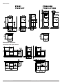
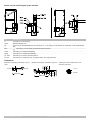
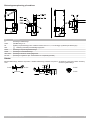
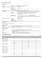
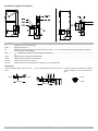
Abmessungen
PTD 901
PTD 901 LIFT
PTD 901 ECO
PTD 901 LIFT ECO
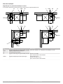
Abmessungen mit Tischen
Aufstellung Tischtiefe 700 mm

Technische Änderungen vorbehalten | 12020531/01; 2023-04 | 3
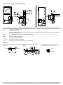
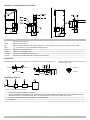
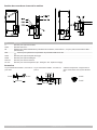
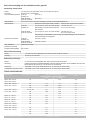
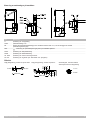
Position der Anschlüsse an der Maschine
Pos. Bezeichnung
A Anschluss für Ablaufschlauch
TWW Wasseranschluss G ¾“
EZ Einführung für Netzanschlussleitung (innerhalb der Maschine benötigt man ca. 1,7 m für das Verlegen und Anschließen
der Netzanschlussleitung)
PPE Anschluss für bauseitiges Potentialausgleichssystem
DOS1 Anschluss für Klarspülerschlauch
DOS2 Anschluss für Reinigerschlauch
ext. DOS Anschluss für externe Dosiergeräte
DT / RA Anschluss für Sauglanzen (DT: Reiniger / RA: Klarspüler)
Zubehör
flexibler Zulaufschlauch; an Punkt TWw an-
schließen
flexibler Ablaufschlauch; an Punkt A an-
schließen
Schmutzfänger; zwischen Wasserabsperr-
ventil und Zulaufschlauch einbauen
G 3/4" G 3/4"
1500 mm
1500 mm
Ø 24
Ø 28
Ø 46
Ø 18,5
Ø 22,2
Ø 39,7
G 3/4"
G 3/4"

Technische Änderungen vorbehalten | 12020531/01; 2023-04 | 4
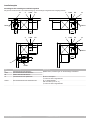
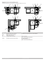
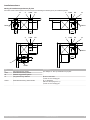
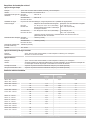
Installationsplan
Vorschlag für die bauseitigen Installationspunkte
Die genauen Maße müssen unter Berücksichtigung der bauseitigen Gegebenheiten festgelegt werden.
A EZTWW
AA1 EZ
TWW
TWW1
200
A1
TWW1
400
A1
TWW1
AEZ
TWW
200
AEZ
TWW A1
TWW1
400
200
Pos. Bezeichnung Bemerkung
A Abwasseranschluss Maschine Details siehe „Anforderungen an die bauseitige Installation“
TWW Frischwasseranschluss Maschine
EZ Elektro-Wandanschlussdose
A1 Abwasseranschluss Spülbecken Ø 50 mm mit Siphon
ca. 300 mm über Fertigfußboden
TWW1 Frischwasseranschluss Wasserarmatur G ½“ Außengewinde
kalt und warm (max. 60 °C)
ca. 500 mm über Fertigfußboden

Technische Änderungen vorbehalten | 12020531/01; 2023-04 | 5
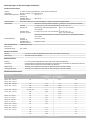
Anforderungen an die bauseitige Installation
Frischwasseranschluss
Position ca. 500 mm über Fertigfußboden; rechts neben der Maschine
Ausführung Absperrventil mit G¾“ Außengewinde
Zulaufwassertemperatur PTD 901,
PTD901 Lift
max. 60 °C
PTD 901 ECO,
PTD 901 Lift ECO
max. 20 °C
Wasserqualität Das Frischwasser muss in mikrobiologischer Hinsicht Trinkwasserqualität besitzen
Wasserhärte Maschinen ohne eingebauten Enthärter Maschinen mit eingebautem Enthärter
PTD 901,
PTD901 Lift
≤ 3 °dH (3,8°e / 5,34°TH / 0,54mmol/l)
Empfehlung, damit die Spülmaschine
nicht verkalkt.
≤ 31°dH (37,6°e /
53,4°TH / 5,35mmol/l)
PTD 901 ECO,
PTD 901 Lift ECO
≤ 3 °dH (3,8°e / 5,34°TH / 0,54mmol/l) ≤ 20°dH (25,1°e /
35,6°TH / 3,58mmol/l)
Anschluss an Osmosewasser ist wegen der Kupferrohre im Abluftwärmetauscher
nicht erlaubt
Wasserfließdruck PTD 901,
PTD901 Lift
100kPa (1,0bar)
PTD 901 ECO,
PTD 901 Lift ECO
150kPa (1,5bar)
Max. Eingangsdruck
(Staudruck)
1000kPa (10,0bar)
Durchflussmenge min. 4l/min
Abwasseranschluss
Position max. 650 mm über Fertigfußboden; links oder rechts neben der Maschine
Abmessung Ø40 oder 50 mm mit Siphon
Elektroanschluss
Position ca. 700 mm über Fertigfußboden; links oder rechts neben der Maschine
Ausführung Falls bauseitig ein Fehlerstromschutzschalter vorgesehen wird, empfehlen wir den Einbau eines all-
stromsensitiven Fehlerstromschutzschalters der Klasse B
Absicherung Abhängig vom Gesamtanschlusswert der Maschine (siehe separate Tabelle)
Leitungsquerschnitt Abhängig vom Gesamtanschlusswert der Maschine (siehe separate Tabelle)
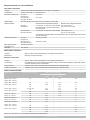
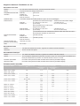
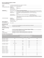
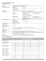
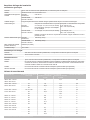
Gesamtanschlusswerte
Netzspannung Bauseitige Absicherung [A] Gesamtanschlusswert [kW] Leitungsquerschnitt [mm²]
Boilerheizung
6,4 kW
Boilerheizung
10,8 kW
380 V / 3N~ / 50 Hz
380 V / 3N~ / 60 Hz
16 7,1 8,3 2,5
400 V / 3N~ / 50 Hz
400 V / 3N~ / 60 Hz
16 7,9 9,1 2,5
25 10,2 13,2 4
32 - 14,7 6
415 V / 3N~ / 50 Hz
415 V / 3N~ / 60 Hz
15 / 16 / 20 8,4 9,7 2,5
25 10,9 11,5 4
32 - 15,7 6
200 V / 3~ / 50 Hz
200 V / 3~ / 60 Hz
25 6,6 7,1 4
32 8,0 9,0 6
230 V / 3~ / 50 Hz
230 V / 3~ / 60 Hz
25 7,8 - 4
32 10,1 - 6
230 V / 1N~ / 50 Hz
230 V / 1N~ / 60 Hz
32 6,9 - 6
240 V / 1N~ / 50 Hz
240 V / 1N~ / 60 Hz
25 5,1 - 4
32 7,0 - 6
40 9,0 - 10
50 10,9 - 10

Subject to technical alterations | 12020531/01; 2023-04 | 6
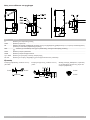
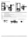
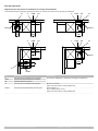
Dimensions
PTD 901
PTD 901 LIFT
PTD 901 ECO
PTD 901 LIFT ECO
Dimensions with tables
Installation table depth 700 mm

Subject to technical alterations | 12020531/01; 2023-04 | 7
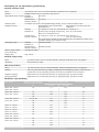
Location of connections on the machine
Item Name
A Connection for drain hose
TWW Water connection G ¾”
EZ Entry for mains cable (inside the machine approx. 1.7 m is required for laying and connecting the mains cable)
PPE Connection for on-site equipotential bonding system
DOS1 Connection for rinse aid hose
DOS2 Connection for detergent hose
ext. DOS Connection for external dosing devices
DT / RA Connection for suction tubes (DT: detergent / RA: rinse aid)
Accessories
Flexible supply hose; connect to point TWw Flexible drain hose; connect to point A Dirt trap; install between the water stop cock
and the supply hose
G 3/4" G 3/4"
1500 mm
1500 mm
Ø 24
Ø 28
Ø 46
Ø 18,5
Ø 22,2
Ø 39,7
G 3/4"
G 3/4"
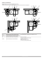
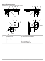
Installation diagram
1234
only for Australia and New Zealand
1 On-site water tap (provided by the customer)
2 Only for Australia and New Zealand: This appliance must be installed according to AS/NZS 3500.1 and AS/NZS 3500.2. This
dishwasher has been supplied separately with a separate backflow prevention device (dual check valve).
3 Water inlet filter (included in scope of delivery of the dishwasher)
4 Dishwasher

Subject to technical alterations | 12020531/01; 2023-04 | 8
Suggestion for the on-site installation points
The exact dimensions must be determined, taking local conditions into account.
A EZTWW
AA1 EZ
TWW
TWW1
200
A1
TWW1
400
A1
TWW1
AEZ
TWW
200
AEZ
TWW A1
TWW1
400
200
Item Name Note
A Machine waste water connection For details, see “Requirements for on-site installation”
TWW Machine inlet water connection
EZ Electric wall junction box
A1 Sink waste water connection Ø50 mm with trap
approx. 300 mm above finished floor
TWW1 Inlet water connection water armature G ½” external thread
cold and warm (max. 60 °C)
approx. 500 mm above finished floor

Subject to technical alterations | 12020531/01; 2023-04 | 9
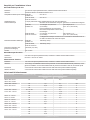
Requirements for on-site installation
Inlet water connection
Location approx. 500 mm above finished floor; to the right of the machine
Construction Isolation valve with G ¾” external thread
Inlet water temperature PTD 901,
PTD901 Lift
max. 60°C
PTD 901 ECO,
PTD 901 Lift ECO
max. 20°C
Water quality Microbiologically, fresh water must be of drinking water quality
Water hardness Machines without integrated softener Machines with integrated softener
PTD 901,
PTD901 Lift
≤ 3°dH (3.8°e / 5.34°TH / 0.54 mmol/l)
Recommended, to prevent warewasher
from scaling up.
≤ 31°dH (37.6°e /
53.4°TH / 5.35mmol/l)
PTD 901 ECO,
PTD 901 Lift ECO
≤ 3°dH (3.8°e / 5.34°TH / 0.54 mmol/l) ≤ 20°dH (25.1°e /
35.6°TH / 3.58mmol/l)
Connection of osmosis water is not permitted due to the copper pipes in the waste
air heat exchanger
Water flow pressure PTD 901,
PTD901 Lift
100kPa (1,0bar)
PTD 901 ECO,
PTD 901 Lift ECO
150kPa (1,5bar)
Max. inlet pressure
(back pressure)
1000kPa (10,0bar)
Flow rate min. 4l/min
Waste water connection
Location approx. 650 mm above finished floor; left or right of the machine
Dimensions Ø40 mm or 50 mm with trap
Electrical connection
Location approx. 700 mm above finished floor; left or right of the machine
Construction If a residual current circuit breaker is provided on-site, we recommend installing a Class B all-current
sensitive residual current circuit breaker
Fuse protection Depends on the total connected load of the machine (see separate table)
Cable cross-section Depends on the total connected load of the machine (see separate table)
Total connected loads
Mains voltage On-site fuse protection [A] Total connected load [kW] Cable cross-section [mm²]
Boiler heating
6.4 kW
Boiler heating
10.8 kW
380 V / 3N~ / 50 Hz
380 V / 3N~ / 60 Hz
16 7,1 8,3 2,5
400 V / 3N~ / 50 Hz
400 V / 3N~ / 60 Hz
16 7,9 9,1 2,5
25 10,2 13,2 4
32 - 14,7 6
415 V / 3N~ / 50 Hz
415 V / 3N~ / 60 Hz
15 / 16 / 20 8,4 9,7 2,5
25 10,9 11,5 4
32 - 15,7 6
200 V / 3~ / 50 Hz
200 V / 3~ / 60 Hz
25 6,6 7,1 4
32 8,0 9,0 6
230 V / 3~ / 50 Hz
230 V / 3~ / 60 Hz
25 7,8 - 4
32 10,1 - 6
230 V / 1N~ / 50 Hz
230 V / 1N~ / 60 Hz
32 6,9 - 6
240 V / 1N~ / 50 Hz
240 V / 1N~ / 60 Hz
25 5,1 - 4
32 7,0 - 6
40 9,0 - 10
50 10,9 - 10
230 V / 1N~ and 240 V / 1N~ don't apply for Australia and New Zealand.

Sous réserve de modifications techniques | 12020531/01; 2023-04 | 10
Dimensions
PTD 901
PTD 901 LIFT
PTD 901 ECO
PTD 901 LIFT ECO
Dimensions avec tables
Installation profondeur de table 700mm

Sous réserve de modifications techniques | 12020531/01; 2023-04 | 11
Position des raccords au niveau de la machine
Pos. Désignation
A Raccord pour tuyau d’évacuation
TWW Raccord d’eau G ¾“
EZ Entrée pour le câble d’alimentation (à l’intérieur de la machine, il faut environ 1,7m pour poser et raccorder le câble
d’alimentation)
PPE Raccord pour système de compensation du potentiel installé sur le site
DOS1 Raccord pour tuyau de liquide de rinçage
DOS2 Raccord pour tuyau de détergent
DOS ext. Raccord pour doseurs externes
DT / RA Raccord pour cannes d’aspiration (DT: détergent / RA: liquide de rinçage)
Accessoires
Tuyau d’alimentation flexible; raccorder au
point TWw
Tuyau d’évacuation flexible; raccorder au
point A
Collecteur d'impuretés; intégrer entre la
vanne d’arrêt d’eau et le tuyau d’alimenta-
tion
G 3/4" G 3/4"
1500 mm
1500 mm
Ø 24
Ø 28
Ø 46
Ø 18,5
Ø 22,2
Ø 39,7
G 3/4"
G 3/4"

Sous réserve de modifications techniques | 12020531/01; 2023-04 | 12
Schéma d’installation
Proposition pour les points d’installation sur site
Les dimensions exactes doivent être définies en prenant en compte les conditions sur site.
A EZTWW
AA1 EZ
TWW
TWW1
200
A1
TWW1
400
A1
TWW1
AEZ
TWW
200
AEZ
TWW A1
TWW1
400
200
Pos. Désignation Remarque
A Raccord des eaux usées machine Pour plus de détails, voir «Exigences relatives à l’installation sur
site»
TWW Raccord de l’eau claire machine
EZ Boîte de jonction murale électrique
A1 Raccord des eaux usées lavabo Ø 50mm avec siphon
env. 300mm au-dessus du sol fini
TWW1 Raccord d’eau claire robinetterie Filetage extérieur G ½“
froid et chaud (max. 60°C)
env. 500mm au-dessus du sol fini

Sous réserve de modifications techniques | 12020531/01; 2023-04 | 13
Exigences relatives à l’installation sur site
Raccord de l’eau claire
Position env. 500mm au-dessus du sol fini; à droite à côté de la machine
Version Soupape d’arrêt avec filetage extérieur G¾“
Température de l’eau d’ali-
mentation
PTD 901,
PTD901 Lift
max. 60°C
PTD 901 ECO,
PTD 901 Lift ECO
max. 20°C
Qualité de l’eau L’eau claire doit être de qualité potable d’un point de vue microbiologique
Dureté de l’eau Machines sans adoucisseur intégré Machines avec adoucisseur intégré
PTD 901,
PTD901 Lift
≤ 3 °dH (3,8°e / 5,34°TH /
0,54mmol/l)
Recommandation pour éviter l’entar-
trage du lave-vaisselle.
≤ 31°dH (37,6°e /
53,4°TH / 5,35mmol/l)
PTD 901 ECO,
PTD 901 Lift ECO
≤ 3 °dH (3,8°e / 5,34°TH /
0,54mmol/l)
≤ 20°dH (25,1°e /
35,6°TH / 3,58mmol/l)
Le raccordement en eau osmosée est interdit en raison des tuyaux en cuivre
de l'échangeur thermique de l'air évacué
Pression d’écoulement
d’eau
PTD 901,
PTD901 Lift
100kPa (1,0bar)
PTD 901 ECO,
PTD 901 Lift ECO
150kPa (1,5bar)
Pression d’entrée max.
(pression d’accumulation)
1000kPa (10,0bar)
Débit min. 4l/min
Raccord eaux usées
Position max. 650mm au-dessus du sol fini; à gauche ou à droite à côté de la machine
Dimension Ø40 ou 50mm avec siphon
Raccordement électrique
Position env. 700mm au-dessus du sol fini; à gauche ou à droite à côté de la machine
Version Si un interrupteur différentiel de protection est prévu sur site, nous recommandons l’installation d’un
interrupteur différentiel de protection de classe B sensible à tous les courants
Protection par fusibles En fonction de la puissance totale raccordée de la machine (voir tableau séparé)
Section de câble En fonction de la puissance totale raccordée de la machine (voir tableau séparé)
Puissance totale raccordée
Tension du réseau Protection par fusibles du site
[A]
Puissance totale raccordée [kW] Section de câble [mm²]
Surchauffeur
6,4kW
Surchauffeur
10,8 kW
380V / 3N~ / 50Hz
380V / 3N~ / 60Hz
16 7,1 8,3 2,5
400V / 3N~ / 50Hz
400V / 3N~ / 60Hz
16 7,9 9,1 2,5
25 10,2 13,2 4
32 - 14,7 6
415V / 3N~ / 50Hz
415V / 3N~ / 60Hz
15 / 16 / 20 8,4 9,7 2,5
25 10,9 11,5 4
32 - 15,7 6
200V / 3~ / 50Hz
200 V / 3~ / 60 Hz
25 6,6 7,1 4
32 8,0 9,0 6
230V / 3~ / 50Hz
230V / 3~ / 60Hz
25 7,8 - 4
32 10,1 - 6
230 V / 1N~ / 50 Hz
230 V / 1N~ / 60Hz
32 6,9 - 6
240V / 1N~ / 50Hz
240V / 1N~ / 60Hz
25 5,1 - 4
32 7,0 - 6
40 9,0 - 10
50 10,9 - 10

Con riserva di modifiche tecniche | 12020531/01; 2023-04 | 14
Dimensioni
PTD 901
PTD 901 LIFT
PTD 901 ECO
PTD 901 LIFT ECO
Dimensioni con i ripiani
Installazione profondità ripiano 700 mm

Con riserva di modifiche tecniche | 12020531/01; 2023-04 | 15
Posizione dei collegamenti sulla macchina
Pos. Denominazione
A Collegamento per tubo di scarico
TWW Raccordo dell’acqua G ¾“
EZ Ingresso per il cavo di alimentazione (all’interno della macchina occorre disporre di circa 1,7 m di spazio per la posa e il
collegamento del cavo di alimentazione)
PPE Collegamento per il sistema di collegamento equipotenziale in loco
DOS1 Collegamento per il tubo flessibile del brillantante
DOS2 Collegamento per il tubo flessibile del detersivo
DOS est. Attacco per dosatori esterni
DT / RA Collegamento per tubi di aspirazione (DT: detersivo / RA: brillantante)
Accessori
tubo flessibile di carico; collegare al punto
TWw
tubo di scarico flessibile; collegare al punto
A
filtro; da installare fra il rubinetto dell’acqua
e il tubo di carico
G 3/4" G 3/4"
1500 mm
1500 mm
Ø 24
Ø 28
Ø 46
Ø 18,5
Ø 22,2
Ø 39,7
G 3/4"
G 3/4"

Con riserva di modifiche tecniche | 12020531/01; 2023-04 | 16
Schema di installazione
Suggerimento per i punti di installazione in loco
Le misure esatte devono essere stabilite tenendo conto delle condizioni del sito di installazione.
A EZTWW
AA1 EZ
TWW
TWW1
200
A1
TWW1
400
A1
TWW1
AEZ
TWW
200
AEZ
TWW A1
TWW1
400
200
Pos. Denominazione Nota
A Raccordo acqua di scarico della macchina Per i dettagli vedere i “Requisiti per l’installazione in loco”
TWW Raccordo dell'acqua di rete della macchina
EZ Scatola di collegamento elettrica a parete
A1 Raccordo acqua di scarico del lavandino Ø50 mm con sifone
ca. 300 mm sopra il pavimento finito
TWW1 Raccordo dell'acqua di rete rubinetteria Filettatura esterna G ½“
fredda e calda (max. 60 °C)
ca. 500 mm sopra il pavimento finito

Con riserva di modifiche tecniche | 12020531/01; 2023-04 | 17
Requisiti per l’installazione in loco
Raccordo dell’acqua di rete
Posizione ca. 500 mm sopra il pavimento finito; a destra accanto alla macchina
Versione Valvola di arresto con filettatura esterna G ¾”
Temperatura dell'acqua in entrata PTD 901,
PTD901 Lift
max. 60 °C
PTD 901 ECO,
PTD 901 Lift ECO
max. 20 °C
Qualità dell’acqua L’acqua pulita deve essere potabile dal punto di vista microbiologico
Durezza dell’acqua Macchine senza addolcitore integrato Macchine con addolcitore integrato
PTD 901,
PTD901 Lift
≤ 3 °dH (3,8°e / 5,34°TH /
0,54mmol/l)
Raccomandazione per prevenire la
formazione di depositi di calcare nella
lavastoviglie.
≤31°dH (37,6°e /
53,4°TH / 5,35mmol/l)
PTD 901 ECO,
PTD 901 Lift ECO
≤ 3 °dH (3,8°e / 5,34°TH /
0,54mmol/l)
≤20°dH (25,1°e /
35,6°TH / 3,58mmol/l)
Il collegamento all'acqua osmotica non è consentito a causa dei tubi in ra-
me dello scambiatore di calore del vapore
Pressione dinamica dell'acqua PTD 901,
PTD901 Lift
100kPa (1,0bar)
PTD 901 ECO,
PTD 901 Lift ECO
150kPa (1,5bar)
Pressione d’ingresso max.
(pressione di ristagno)
1000kPa (10,0bar)
Portata min. 4l/min
Raccordo acqua di scarico
Posizione max. 650 mm sopra il pavimento finito; a sinistra o a destra accanto alla macchina
Dimensione Ø40 mm o 50 mm con sifone
Allacciamento elettrico
Posizione max. 700 mm sopra il pavimento finito; a sinistra o a destra accanto alla macchina
Versione Se nel luogo di installazione deve essere presente un interruttore differenziale di protezione, consi-
gliamo di installare un interruttore differenziale di protezione sensibile a tutte le correnti del tipo B
Protezione A seconda del valore totale di allacciamento della macchina (vedere tabella separata)
Sezione del cavo A seconda del valore totale di allacciamento della macchina (vedere tabella separata)
Valori totali di allacciamento
Tensione di rete Protezione in loco [A] Valore totale di allacciamento [kW] Sezione del cavo [mm²]
Riscaldamento boiler
6,4 kW
Riscaldamento boiler
10,8 KW
380 V / 3N~ 50 Hz
380 V / 3N~ / 60 Hz
16 7,1 8,3 2,5
400 V / 3N~ / 50 Hz
400 V / 3N~ 60 Hz
16 7,9 9,1 2,5
25 10,2 13,2 4
32 - 14,7 6
415 V / 3N~ / 50 Hz
415 V / 3N~ / 60 Hz
15 / 16 / 20 8,4 9,7 2,5
25 10,9 11,5 4
32 - 15,7 6
200 V / 3~ / 50 Hz
200 V / 3~ / 60 Hz
25 6,6 7,1 4
32 8,0 9,0 6
230 V / 3~ / 50 Hz
230 V / 3~ / 60 Hz
25 7,8 - 4
32 10,1 - 6
230 V / 1N~ / 50 Hz
230 V / 1N~ / 60 Hz
32 6,9 - 6
240 V / 1N~ / 50 Hz
240 V / 1N~ / 60 Hz
25 5,1 - 4
32 7,0 - 6
40 9,0 - 10
50 10,9 - 10

Technische wijzigingen voorbehouden | 12020531/01; 2023-04 | 18
Afmetingen
PTD 901
PTD 901 LIFT
PTD 901 ECO
PTD 901 LIFT ECO
Afmetingen met tafels
Installatie tafeldiepte 700 mm

Technische wijzigingen voorbehouden | 12020531/01; 2023-04 | 19
Positie van de aansluitingen op de machine
Pos. Omschrijving
A Aansluiting voor afvoerslang
TWW Wateraansluiting G ¾”
EZ Invoer van de netaansluitkabel (in de machine is ca. 1,7 m nodig voor het plaatsen en aansluiten van de netaansluitka-
bel)
PPE Aansluiting voor bouwzijdig potentiaalnivelleringssysteem
DOS1 Aansluiting voor naglansmiddelslang
DOS2 Aansluiting voor reinigingsmiddelslang
ext. DOS Aansluiting voor externe doseersystemen
DT / RA Aansluiting voor zuiglansen (DT: reinigingsmiddel / RA: naglansmiddel)
Toebehoren
flexibele toevoerslang; aansluiten op punt
TWw
flexibele afvoerslang; aansluiten op punt A Vuilvanger; tussen waterkraan en toe-
voerslang inbouwen
G 3/4" G 3/4"
1500 mm
1500 mm
Ø 24
Ø 28
Ø 46
Ø 18,5
Ø 22,2
Ø 39,7
G 3/4"
G 3/4"

Technische wijzigingen voorbehouden | 12020531/01; 2023-04 | 20
Installatieschema
Suggestie voor de bouwzijdige installatiepunten
De exacte maten moeten met inachtneming van de bouwzijdige omstandigheden worden vastgelegd.
A EZTWW
AA1 EZ
TWW
TWW1
200
A1
TWW1
400
A1
TWW1
AEZ
TWW
200
AEZ
TWW A1
TWW1
400
200
Pos. Omschrijving Opmerking
A Afvoerwateraansluiting machine Zie voor details "Eisen die bouwzijdig aan de installatie worden ge-
steld"
TWW Schoonwateraansluiting machine
EZ Elektrische wandcontactdoos
A1 Afvoerwateraansluiting spoelbak Ø 50 mm met sifon
ca. 300 mm boven afgewerkte vloer
TWW1 Schoonwateraansluiting waterarmatuur G ½” buitendraad
koud en warm (max. 60 °C)
ca. 500 mm boven afgewerkte vloer
La pagina si sta caricando...
La pagina si sta caricando...
La pagina si sta caricando...
La pagina si sta caricando...
La pagina si sta caricando...
La pagina si sta caricando...
La pagina si sta caricando...
La pagina si sta caricando...
La pagina si sta caricando...
La pagina si sta caricando...
La pagina si sta caricando...
La pagina si sta caricando...
La pagina si sta caricando...
La pagina si sta caricando...
La pagina si sta caricando...
La pagina si sta caricando...
La pagina si sta caricando...
La pagina si sta caricando...
La pagina si sta caricando...
La pagina si sta caricando...
La pagina si sta caricando...
La pagina si sta caricando...
La pagina si sta caricando...
La pagina si sta caricando...
La pagina si sta caricando...
La pagina si sta caricando...
La pagina si sta caricando...
La pagina si sta caricando...
-
 1
1
-
 2
2
-
 3
3
-
 4
4
-
 5
5
-
 6
6
-
 7
7
-
 8
8
-
 9
9
-
 10
10
-
 11
11
-
 12
12
-
 13
13
-
 14
14
-
 15
15
-
 16
16
-
 17
17
-
 18
18
-
 19
19
-
 20
20
-
 21
21
-
 22
22
-
 23
23
-
 24
24
-
 25
25
-
 26
26
-
 27
27
-
 28
28
-
 29
29
-
 30
30
-
 31
31
-
 32
32
-
 33
33
-
 34
34
-
 35
35
-
 36
36
-
 37
37
-
 38
38
-
 39
39
-
 40
40
-
 41
41
-
 42
42
-
 43
43
-
 44
44
-
 45
45
-
 46
46
-
 47
47
-
 48
48


