
EN
V3.1 Supplementary Manual
This supplementary manual explains mainly the functions that have been added or changed in QL5/QL1
firmware V3.1.
Use it in conjunction with the QL5/QL1 V3 Owner's Manual and Reference Manual.

Contents
V3.1 Supplementary Manual
2
Contents
Input channels .......................................................................... 3
Added pan function (Monaural input channels only) ............................................... 3
Changing input signal processing when setting LR-MONO
(Stereo input channels only) ......................................................................... 4
I/O Devices window .................................................................. 5
Added supported devices ........................................................................................ 5
Added third-party equipment’s HA control function ................................................ 7
Setup window ........................................................................... 8
Added functions for cascade connections ................................................................ 8
Channel job............................................................................. 10
Added parameters to Recall Safe function .............................................................. 10
Scene memory......................................................................... 11
Added parameters to Global Paste function ........................................................... 11
Added parameters to Focus Recall function............................................................ 11
SAVE/LOAD window ............................................................... 12
Added remount function to USB flash drives.......................................................... 12
Other functions....................................................................... 13
Changed update procedure for NAME SUB CPU firmware ..................................... 13
Added update function to Dante firmware............................................................. 13

Input channels
V3.1 Supplementary Manual
3
Input channels
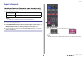
Added pan function (Monaural input channels only)
The pan setting for signals sent to the STEREO bus enables you to select PAN LAW settings.
You can select one of the following:
NOTE
The settings are also applied to the signals sent to the stereo MIX buses.
1 PAN LAW select button
This toggle button is used to set the PAN LAW for the Input Channel.
For CENTER NOMINAL For LR NOMINAL
NOTE
PAN LAW settings are also enabled in LCR mode. They are also enabled in Surround mode.
CENTER NOMINAL
The pan level is nominal at center and +3dB when panned 100%
either left or right.
LR NOMINAL
The pan level is -3dB at center and nominal when panned 100%
either left or right.
STEP
1. Select a monaural input channel.
2. In the STEREO/MONO field, press a knob to select the channel you want to adjust in
the OVERVIEW window, and then press the knob once again. Or, in the PAN/
BALANCE field, press a knob to select the channel you want to adjust in the
SELECTED CHANNEL window, and then press the knob once again.
3. Use the PAN LAW select button in the TO STEREO/MONO window to set the PAN
LAW for each channel.
1

Input channels
V3.1 Supplementary Manual
4
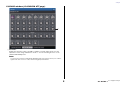
You can also check the status of PAN LAW settings in the window shown below. For channels
where the mark is on, PAN LAW is set to LR NOMINAL.
• TO STEREO/MONO window (CH1–32, CH33–64/ST IN (QL5), ST IN (QL1))
• OVERVIEW window (STEREO/MONO field)
• SELECTED CHANNEL VIEW window (PAN/BALANCE field)
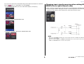
Changing input signal processing when setting LR-
MONO (Stereo input channels only)
In order to ensure the appropriate level, the signal processing regarding the LR-MONO setting
has been changed as follows. Although the result is a monaural signal that is the summation
of signals from both channels, the R channel of the stereo input channel is muted.
NOTE
• When you set LR-MONO, the PAN mode is selected at the same time. In addition, the PAN knob
is set to the center position.
• When you set LR, L-MONO, or R-MONO, the BALANCE mode is selected at the same time. In
addition, the BALANCE knob is set to the center position.

I/O Devices window
V3.1 Supplementary Manual
5
I/O Devices window
Added supported devices
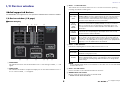
The RSio64-D is now supported. You can operate the RSio64-D in the I/O Devices window.
I/O Devices window (I/O page)
Q RSio64-D display
1
CARD NAME
This indicates the names of the cards installed in slots 1 to 4. If nothing is installed,
“----”
will
appear.
2 IN/OUT PORT
This indicates the number of input and output ports for the cards installed in slots 1 to
4. If no card is installed, “--” will appear.
3 SLOT 1 - 4 LOCK indicators
This indicates the word clock status for slots 1 to 4. If the word clock is operating
normally, this indicator will be green.
4 SLOT 1 - 4 SRC indicators
Indicate the Sampling Rate Converter (SRC) status for slots 1 to 4.
NOTE
Use the SRC WCLK DIP switches on the RSio64-D to set the SRC clock sent to the Mini-YGDAI
card inserted in the slot.
5 SLOT 1 to 4 SRC buttons
Used to turn SRC on/off at both IN and OUT for each slot.
6 WORD CLOCK select button
Used to select the word clock source for the RSio64-D.
• WORD CLOCK WCLK IN indicator
1 5243B
0A67 8 9
Off There is no card in the slot. Or, an unsupported card is in the slot.
Green (On)
LOCK
Indicates that a clock synchronized with the clock source selected with the
[WORD CLOCK] select key is being input from the card. If an external device
is connected to the corresponding slot, input/output is occurring properly
between that device and the RSio64-D. If the sampling frequency is close,
this status may be displayed even if not synchronized.
Green
(Flashing)
SYNC
ERROR
A valid clock is being input from the card, but is not synchronized with the
clock source selected with the [WORD CLOCK] select key. If an external
device is connected to the corresponding slot, input/output cannot occur
correctly between that device and the RSio64-D. Turn SRC ON for correct
input/output.
Red (On)
UNLOCK
A valid clock is not being input from the card. If an external device is
connected to the corresponding slot, input/output cannot occur correctly
between that device and the RSio64-D.
Red
(Flashing)
WRONG
WORD
CLOCK
The frequency of the clock source selected with the [WORD CLOCK] select
key is outside of the operating frequency range for the card inserted in the
slot. Either set the frequency of the clock source within the operating range
for the card, or turn [SRC] ON. For an analog card, if you turn [SRC] ON, the
frequency is set to the 48kHz built into the RSio64-D.
Off SRC is off.
Green (On)
SRC is on, and the clock selected with the SRC WCLK DIP switches on the
RSio64-D is being input correctly.
Red (On)
SRC is on, but an appropriate clock is not being input. The clock selected
with the SRC WCLK DIP switches on the RSio64-D is either not being input
or is not within the operating range. Either turn SRC off, or change the DIP
switch settings.

I/O Devices window
V3.1 Supplementary Manual
6
• WORD CLOCK SLOT1 1/2 indicator
• WORD CLOCK DANTE indicator
Indicates the word clock source status for the RSio64-D.
*1 When flashing, Dante word clock
*3
input/output is used.
*2 If you are using MY8-AEB, set the AEÙRSVD switch for the card to RSVD.
*3 If you make changes to the frequency of the Dante word clock, use Dante Controller.
7 CURRENT PATTERN button
If you press this button, the currently selected routing pattern on the RSio64-D is displayed.
If you switch the routing pattern on the RSio64-D, it will be applied in 3 seconds.
8 USER PATTERN button
Press this button to open the window for setting the audio routing user pattern in the
RSio64-D. Patch to the desired output ports of the slots and Dante.
NOTE
Patching from one slot to another is also available (including patching to the same slot). However,
you cannot patch from Dante to Dante.
9 OUTPUT PATCH button
Press this button to open the OUTPUT PATCH window, in which you can set the 64
Dante channels that will be output from the console to the RSio64-D.
0 POWER INT indicator
Indicates the status of the AC IN power supply for the RSio64-D. If the power switch is
off, no power is supplied to AC IN and the indicator remains off.
A POWER EXT indicator
Indicates the status of the EXT DC INPUT power supply for the RSio64-D. If the power
supply is on, this indicator will be on. This indicator is not affected by the status of the
power switch.
B Control status indicator
Indicates the control status of the device.
WCLK IN
On when using the word clock signal being input from the WORD
CLOCK IN connector on the rear panel of the RSio64-D. Flashes
*1
if
there is no valid word clock input.
SLOT1 1/2
On when using the word clock for channels 1/2 of slot 1 for the RSio64-
D. Flashes
*1
if there is no valid word clock input. When using MY8-
AEB
*2
, the word clock for channels 7/8 is used.
DANTE
On when using the word clock for the Dante network
*3
. (If there is no
valid Dante signal input, the internal Dante module will generate a
clock.)
Searching for device to be controlled
Connecting to device
Synchronizing with device
Device can be controlled

I/O Devices window
V3.1 Supplementary Manual
7
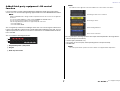
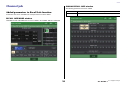
Added third-party equipment’s HA control
function
It is now possible to control supported third-party equipment’s head amps (HA) from the
console. You can control HA by registering supported devices in the DANTE SETUP window.
NOTE
While in PREVIEW mode, changes made to HA parameters from the console are not applied to
the device.
You can turn “WITH RECALL” on and off in the REMOTE HA ASSIGN window.
You can store/recall scene libraries and save/load files.
The following third-party products are supported by QL series V3.1:
• Focusrite RedNet 4
• Focusrite RedNet MP8R
You can register up to 8 devices, including R series units. You can also register a device that
has the same UNIT ID as a device that is already registered, including R series units. You can
adjust HA parameters in advance, even when a connection is not established with the device
to be controlled.
You can control the following parameters.
1 HA phantom power (+48V) on/off
2 HA gain
3 Head amp HPF on/off
NOTE
The indicator on the right side of the rack indicates the control status of the device.
You can perform the following operations from input channels patched to the target device:
• Store/recall input channel library
• Channel jobs (channel link, etc.)
• HA controls at user level (only when operating HA from an input channel)
• AG-DG LINK
NOTE
You cannot perform this operation on devices that do not support Gain Compensation.
1
2
3
Searching for device to be controlled
Connecting to device
Synchronizing with device
Device can be controlled

Setup window
V3.1 Supplementary Manual
8
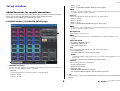
Setup window
Added functions for cascade connections
The number of operations that can be linked when making cascade connections between QL
series consoles has been increased. You can now select multiple operations.
An attenuator is now built into the CASCADE input signal.
CASCADE window (CASCADE IN PATCH page)
1 CASCADE LINK buttons
Used to select the operations to be linked when making cascade connections between
QL series consoles. Multiple selection is possible.
•DCA 1-8
The following parameters related to DCA 1 to 8 will be linked.
• DCA 1 - 8 level
• DCA 1 - 8 on/off
• DCA 1 - 8 cue
• DCA 1 - 8 DCA MUTE TARGET (DCA group mute targets)
NOTE
Even if the cue mode is LAST CUE, the cue for the target DCA will come on at the same time
for consoles linked by cascade connections.
•DCA 9-16
The following parameters related to DCA 9 to 16 will be linked.
•DCA 9 - 16 level
• DCA 9 - 16 on/off
• DCA 9 - 16 cue
• DCA 9 - 16 DCA MUTE TARGET (DCA group mute targets)
NOTE
Even if the cue mode is LAST CUE, the cue for the target DCA will come on at the same time
for consoles linked by cascade connections.
• MUTE MASTER
Links ON/OFF for mute masters.
NOTE
The settings of Dimmer function are not linked. Make these settings individually on each
console.
• SENDS ON FADER
Links SENDS ON FADER behavior.
• SENDS ON FADER mode
• The send destination bus
•CUE
The following cue-related parameters and events will be linked.
• Cue enable/disable
• Cue mode (MIX CUE or LAST CUE, 5.1 SOLO)
NOTE
Regarding 5.1 SOLO, no links are made if the console at the cascade destination is set to
Stereo mode.
• Cue point settings for input channels and output channels
•OTHERS
The following parameters will be linked.
• Scene recall operations
• Scene store operations
• Edit scene titles
• DIMMER (MONITOR window) operations
• Panel LED and display brightness (SETUP window) operations
2 Tabs
Switches between pages (CASCADE IN PATCH, CASCADE IN ATT, and CASCADE OUT
PATCH).
1
2

Setup window
V3.1 Supplementary Manual
9
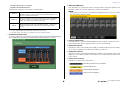
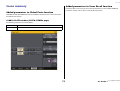
CASCADE window (CASCADE IN ATT page)
1 ATT knobs
Display the attenuator values (-96.0dB to 0.0dB) for cascade input signals. You can
adjust these values using multifunction knobs 1 - 8 in the Centralogic section or the
[TOUCH AND TURN] knob.
NOTE
You can use these knobs as SUB IN with adjustable input level. Doing so allows you to sum the
signals from other consoles to a bus, without using up inputs and buses.
1

Channel job
V3.1 Supplementary Manual
10
Channel job
Added parameters to Recall Safe function
Parameters that can be excluded from recall operations have been added.
RECALL SAFE MODE window
CASCADE IN and CASCADE OUT have been added to the GLOBAL RECALL SAFE field.
GLOBAL RECALL SAFE window
The following parameters have been added.
CASCADE IN CASCADE IN PATCH and CASCADE IN ATT settings
CASCADE OUT CASCADE OUT PATCH settings

Scene memory
V3.1 Supplementary Manual
11
Scene memory
Added parameters to Global Paste function
CASCADE IN and CASCADE OUT have been added as parameters that can be selected for
the Global Paste function.
GLOBAL PASTE window (PATCH/OTHERs page)
The following parameters have been added.
Added parameters to Focus Recall function
Parameters that can be set in the Focus Recall operations have been added. Additional
parameters are the same as those in the Recall Safe function.
CASCADE IN CASCADE IN PATCH and CASCADE IN ATT settings
CASCADE OUT CASCADE OUT PATCH settings

SAVE/LOAD window
V3.1 Supplementary Manual
12
SAVE/LOAD window
Added remount function to USB flash drives
If USB flash drive is not mounted, the FORMAT button will become a USB REMOUNT button.
Press this button to mount a USB flash drive. Use this button if a USB flash drive is not
recognized after it has been removed and reinserted.

Other functions
V3.1 Supplementary Manual
13
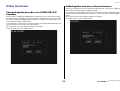
Other functions
Changed update procedure for NAME SUB CPU
firmware
The procedure for updating the NAME SUB CPU firmware for the QL console from a USB
flash drive has been changed. If the following window is displayed, the console has entered
the mode for updating the NAME SUB CPU firmware. For details about this operation, refer
to the “QL5/QL1 Firmware Update Guide”.
If you mistakenly use a file for CL to perform this update, the [TOUCH AND TURN] knobs will
stop functioning. Use this function only if that happens.
Do not power-off the console while the update is proceeding.
To exit this mode, press the CANCEL button.
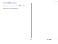
Added update function to Dante firmware
You can now update the firmware for the Dante module in the QL console from a USB flash
drive, without using Dante Firmware Update Manager.
If the following window is displayed, the console has entered the mode for updating the Dante
module firmware. For details about this operation, refer to the “QL5/QL1 Firmware Update
Guide”.
Do not power-off the console while the update is proceeding.
To exit this mode, press the CANCEL button.

Published 07/2015 MA-A0
© 2015 Yamaha Corporation
Manual Development Department
Yamaha Manual Library
http://www.yamaha.co.jp/manual/
Yamaha Pro Audio Global Web Site
http://www.yamahaproaudio.com/
-
 1
1
-
 2
2
-
 3
3
-
 4
4
-
 5
5
-
 6
6
-
 7
7
-
 8
8
-
 9
9
-
 10
10
-
 11
11
-
 12
12
-
 13
13
-
 14
14


Yamaha QL1 Manuale utente
- Categoria
- Controller DJ
- Tipo
- Manuale utente
in altre lingue
- English: Yamaha QL1 User manual
- français: Yamaha QL1 Manuel utilisateur
- español: Yamaha QL1 Manual de usuario
- Deutsch: Yamaha QL1 Benutzerhandbuch
- русский: Yamaha QL1 Руководство пользователя
- Nederlands: Yamaha QL1 Handleiding
- português: Yamaha QL1 Manual do usuário
- dansk: Yamaha QL1 Brugermanual
- čeština: Yamaha QL1 Uživatelský manuál
- polski: Yamaha QL1 Instrukcja obsługi
- svenska: Yamaha QL1 Användarmanual
- Türkçe: Yamaha QL1 Kullanım kılavuzu
- suomi: Yamaha QL1 Ohjekirja
- română: Yamaha QL1 Manual de utilizare