
1/8
Divisione della BETA UTENSILI SPA, Via Volta. 18 - 20845 SOVICO (MB) ITALY Tel. +39.039.20771-Fax + 39.039.2010742
SPECIFICA PRODOTTO
ISTRUZIONI PER L’USO E LA MANUTENZIONE
Informazioni tecniche
Condizioni d’uso previste e limiti operativi
Prescrizioni per gli operatori
Rischi residui
Modalità e frequenza delle ispezioni periodiche d’idoneità
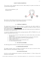
RADANCE INOX ARTICOLO 8220
La lingua originale della presente specifica è quella Italiana.
Sede produttiva Accessori per funi ROBUR
Zona Industriale – C.da S. Nicola
67039 SULMONA (L’AQUILA)
Tel. +39.0864.2504.1 – Fax +39.0864.253132
www.roburitaly.com – [email protected]
R/SP/8220/02
Data 15/01/2016

2/8
Divisione della BETA UTENSILI SPA, Via Volta. 18 - 20845 SOVICO (MB) ITALY Tel. +39.039.20771-Fax + 39.039.2010742
1) CARATTERISTICHE TECNICHE DELL’ACCESSORIO
Materiale:
Acciaio inox AISI 316
Il collaudo viene eseguito in base a specifiche e regole interne in riferimento alla norma UNI EN ISO
9001.

3/8
Divisione della BETA UTENSILI SPA, Via Volta. 18 - 20845 SOVICO (MB) ITALY Tel. +39.039.20771-Fax + 39.039.2010742
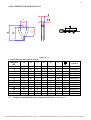
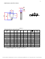
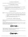
CARATTERISTICHE DIMENSIONALI:
TABELLA “A”
Le quote indicate sono espresse in mm.
MISURA
ØF
A B C D G T
g
CODICE
2
20 18 7.5 4.5 14 80 2
082200202
3
24 21 10 6.0 18 80 3
082200203
4
27 24 11 7.0 20 80 4
082200204
5
30 26 13 8.5 21 110 6
082200205
6
37 33 15 10 26 200 8
082200206
8
47 41 21 12.5 32 225 20
082200208
10
56 50 27 14.5 41 250 30
082200210
12
67 59 31 18 47 250 52
082200212
14
78 69 35 20 50 300 60
082200214
16
82 72 38 23 57 315 82
082200216
18
92 82 42 25 66 335 100
082200218
20
104 93 45 28 75 370 115
082200220
22
112 98 45 30 75 540 155
082200222
T = Lunghezza minima del tratto terminale della fune (vedi figura 1)

4/8
Divisione della BETA UTENSILI SPA, Via Volta. 18 - 20845 SOVICO (MB) ITALY Tel. +39.039.20771-Fax + 39.039.2010742
Definizioni:
• Morsetto: gruppo costituito da cavallotto filettato, un corpo e dadi che consentono la compressione
assieme di due parti di fune quando si serrano i dadi.
• Coppia di serraggio:
è il prodotto tra la forza impiegata per serrare una vite e la lunghezza della
leva con la quale si applica.
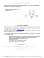
• Radancia: è un anello che viene posto all’interno dell’asola di un cavo per proteggerlo dall’usura
dovuta allo sfregamento con altri elementi, garantendone così l’integrità nel tempo. Ha la forma a
goccia e la sezione a U, che deve essere di misura adeguata al cavo che vi deve trovare
alloggiamento.
• Ispezione: controllo visivo relativo allo stato della radancia per individuare evidenti
danneggiamenti o usure che possono alterarne l’utilizzo.
• Esame accurato: esame visivo effettuato da una persona competente e, se necessario, coadiuvato
da altri mezzi, quali i controlli non-distruttivi, al fine di individuare danneggiamenti o usure che
possono alterare l’utilizzo del componente.
• Persona competente: persona designata, istruita correttamente, qualificata per conoscenza ed
esperienza pratica, che ha ricevuto le istruzioni necessarie per eseguire le prove e gli esami
richiesti.
2) SPECIFICHE DI COLLAUDO
L’accessorio è sottoposto a una serie di severi controlli a campione per accertarne la funzionalità
prestazionale e la rispondenza alle specifiche.
La numerosità dei campioni e i relativi piani di campionamento sono scelti in funzione della
caratteristica da verificare in accordo e per quanto previsto dalla norma UNI ISO 2859/1, e i risultati
archiviati nell’ufficio qualità dello stabilimento di Sulmona.
2.A Controllo dimensionale
Verifica che le dimensioni dell’articolo rientrino nelle tolleranze stabilite dalla
norma.
2.B Controllo visivo
Ha lo scopo di escludere eventuali imperfezioni dovute a processo di fabbricazione,
ammaccature e rispondenza della marcatura a disegni di fase interni.
2.C Analisi chimica
Verifica la rispondenza della composizione chimica del materiale, entro i limiti
stabiliti dalle relative norme.

5/8
Divisione della BETA UTENSILI SPA, Via Volta. 18 - 20845 SOVICO (MB) ITALY Tel. +39.039.20771-Fax + 39.039.2010742
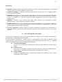
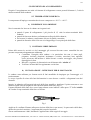
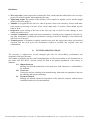
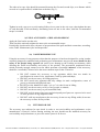
3) COME LEGGERE LA MARCATURA
Sull’accessorio sono stampate in maniera indelebile marcature e sigle che identificano il prodotto e
ne definiscono le caratteristiche e applicazioni.
1) Misura (diametro della fune es. 10)
2) Materiale (316)
La posizione della marcatura sul disegno è solo indicativa.
Realmente le posizioni delle varie voci possono trovarsi in punti differenti.
3) AVVERTENZE GENERALI
Il manuale deve essere custodito da persona responsabile allo scopo preposta, in un luogo idoneo,
affinché esso risulti sempre disponibile per la consultazione nel miglior stato di conservazione. In
caso di smarrimento o deterioramento, la documentazione dovrà essere prontamente sostituita
scaricandola dal sito del costruttore: www.roburitaly.com.
Il costruttore si riserva la proprietà materiale ed intellettuale del presente manuale e ne vieta la
duplicazione, anche parziale, per fini commerciali.
Con riferimento a quanto riportato in queste istruzioni d’uso, la BETA UTENSILI SPA declina ogni
responsabilità in caso di:
• uso degli accessori contrario alle leggi nazionali sulla sicurezza e sull’antinfortunistica;
• errata scelta o predisposizione dell’apparecchio con il quale saranno connessi;
• mancata o errata osservanza delle istruzioni per l’uso;
• modifiche agli accessori;
• uso improprio e omessa manutenzione ordinaria;
• uso combinato ad accessori non conformi.
4) CRITERI DI SCELTA
I parametri che devono essere attentamente considerati nella scelta delle radance sono:
5.A DIAMETRO DELLA FUNE
Le radance devono essere scelte in funzione del diametro della fune da utilizzare (la misura della
radancia corrisponde al diametro nominale della fune).
3
1
6
1
0

6/8
Divisione della BETA UTENSILI SPA, Via Volta. 18 - 20845 SOVICO (MB) ITALY Tel. +39.039.20771-Fax + 39.039.2010742
5.B ELEMENTO DI ACCOPPIAMENTO
Eseguire l’accoppiamento tra asola ed elemento di collegamento con un perno di diametro 1,5 volte la
misura nominale della radancia.
5.C TEMPERATURE D’IMPIEGO
La temperatura d’impiego consentita dovrà essere compresa tra –20 °C e +80 °C.
6) CONDIZIONI NON AMMESSE
Non è consentito far lavorare le radance nei seguenti casi:
• quando il perno di collegamento è più piccolo di 1,5 volte la misura nominale della
radancia;
• quando la fune non aderisce perfettamente nella gola della radancia;
• far lavorare le radance a temperature diverse da quelle consentite;
• quando la direttrice delle forze non si sviluppa lungo l’asse principale della fune.
7) CONTROLLI PRELIMINARI
Prima della messa in servizio e/o del montaggio gli accessori devono essere controllati da una
persona competente adeguatamente addestrata.
• Controllare l’integrità delle radance e in particolare che non vi siano tagli,
piegature, incisioni, abrasioni, incrinature o cricche, corrosioni, bave taglienti,
usure provocate dall’utilizzo o difetti dovuti a cattivo stoccaggio, che possano
danneggiare la fune.
• Rilevare e registrare le dimensioni con riferimento alla “tabella A”.
• Verificare la bontà dell’accoppiamento con la fune.
8) INSTALLAZIONE – ISTRUZIONI PER IL MONTAGGIO
Le radance sono utilizzate per formare asole di funi metalliche da impiegare per l’ancoraggio e il
tensionamento.
Lo scopo è quello di evitare alle funi deformazioni e usure dovute a carichi e sfregamenti con altri
elementi.
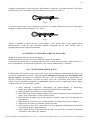
Inserire la radancia nell’estremità ad asola della fune metallica.
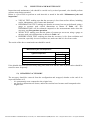
Applicare il primo morsetto a una
distanza uguale alla sua larghezza dall’estremità morta della fune (Fig. 1).
Il tratto terminale della fune deve essere lungo almeno come indicato nella quota “T” della “tabella
A”. Inoltre il capo terminale della fune va fasciato
.
Fig. 1
Applicare il cavallotto filettato sulla parte rinviata della fune (capo morto). La parte attiva della fune,
quella che esercita la trazione, è supportata dal corpo del morsetto.
Serrare uniformemente i dadi, alternando l’applicazione della coppia di serraggio.

7/8
Divisione della BETA UTENSILI SPA, Via Volta. 18 - 20845 SOVICO (MB) ITALY Tel. +39.039.20771-Fax + 39.039.2010742
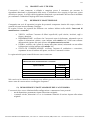
Adagiare perfettamente la fune nella sede della radancia e applicare il secondo morsetto il più vicino
possibile alla stessa, bloccando i dadi fermamente, ma senza serrare (Fig. 2).
Fig. 2
Gli altri morsetti devono essere montati tra il primo e il secondo, distanziati fra di loro di una quota
maggiore o uguale alla loro larghezza “S” (Fig. 3).
Fig. 3
Tendere l’imbando in modo da non creare pieghe o zone lasche sulla corda; quindi serrare
uniformemente i dadi di ogni cavallotto filettato, alternando da un dado all’altro fino al
raggiungimento della coppia raccomandata.
9) USO DELL’ACCESSORIO - PRESA E MANOVRA
Applicare il primo carico per provare il gruppo.
Quindi controllare l’insieme e riserrare i dadi alla coppia raccomandata.
Controllare periodicamente le condizioni della trazione, lo stato di conservazione degli elementi e il
loro accoppiamento, in riferimento alla tabella “Interventi di manutenzione e controllo”.
10) CONTROINDICAZIONI D’USO
L’utilizzo dell’accessorio per scopi non previsti, il suo uso in condizioni estremamente pericolose e la
carenza di manutenzione possono comportare gravi situazioni di pericolo per l’incolumità delle
persone esposte e di danno per l’ambiente di lavoro, oltre che pregiudicare la funzionalità e la
sicurezza effettiva del prodotto. Le azioni di seguito citate, che, ovviamente, non possono coprire
l’intero arco di potenziali possibilità di “cattivo uso” dell’accessorio, costituiscono tuttavia quelle
“ragionevolmente” più prevedibili. Quindi:
• NON utilizzare l’accessorio collegandolo ad apparecchiature di dimensioni,
temperatura, punto d’aggancio e forma non idonei alle sue caratteristiche;
• NON utilizzare l’accessorio per il sollevamento;
• NON mettere in tensione apparecchiature che possono cambiare la loro configurazione
statica, il loro baricentro o lo stato chimico-fisico;
• NON utilizzare le radance per la realizzazione di tiranti “asola–asola” da impiegare nel
sollevamento;
• NON utilizzare l’accessorio per il sollevamento o il trasporto di persone o animali;
• NON usare l’accessorio per trainare carichi vincolati;
• NON operare in aree dove è prescritto l’uso di componenti antideflagranti/antiscintilla
o in presenza di forti campi magnetici;
• NON saldare sull’accessorio particolari metallici, né intervenire con riporti di saldatura
o utilizzarlo come massa per saldatrici.

8/8
Divisione della BETA UTENSILI SPA, Via Volta. 18 - 20845 SOVICO (MB) ITALY Tel. +39.039.20771-Fax + 39.039.2010742
11) IDONEITÀ ALL’UTILIZZO
L’accessorio è stato sottoposto a collaudo a campione presso il costruttore per accertare la
rispondenza funzionale e prestazionale dello stesso. L’utilizzatore deve eseguire in ogni caso, prima
di iniziare a operare, la verifica della rispondenza funzionale e prestazionale dell’accessorio installato
per confermare l’idoneità all’impiego dell’intera installazione.
12) ISPEZIONE E MANUTENZIONE
Comprende una serie di operazioni eseguite da personale competente istruito allo scopo, relative a
controlli ed esami accurati durante l’impiego.
Di seguito l’elenco dei controlli da effettuare con cadenze indicate nella tabella “Interventi di
manutenzione e controllo”.
• VISIVO: verificare l’assenza di difetti superficiali, quali cricche, incisioni, tagli o
fessure, abrasioni.
• DEFORMAZIONE: verificare che l’accessorio non sia deformato, misurando con un
calibro le dimensioni critiche, come indicato nella tabella “A”. NON sono tollerate
deformazioni rispetto alle quote rilevate alla prima messa in servizio.
• USURA: verificare che i punti di contatto non siano usurati, misurando con un calibro
le dimensioni critiche indicate nella tabella “A”.
• STATO DI CONSERVAZIONE: verificare l’assenza di ossidazione e corrosione,
soprattutto in caso di utilizzo all’aperto; verificare l’assenza di cricche.
Le registrazioni di questi controlli devono essere conservate.
Nel caso in cui la radancia sia sottoposta a un utilizzo gravoso, è necessario effettuare le verifiche di
usura e stato di conservazione con maggiore frequenza.
13) DEMOLIZIONE E ROTTAMAZIONE DELL’ACCESSORIO
L’accessorio deve essere eliminato dalla configurazione e rottamato nel caso presenti:
- una deformazione permanente rispetto alla misura originale;
- eventuali cricche, distorsioni e/o se si riscontrano riduzioni di sezione rispetto alla misura
originale.
Tabella interventi di manutenzione e controllo
Tipi d controllo
F
requenza
intervento
Trimestre Anno
Controllo visivo
x
Deformazione
x
Usura
x
Stato di conservazione
x

1/8
Division of BETA UTENSILI SPA, Via Volta, 18 - 20845 SOVICO (MB) ITALY Tel. +39.(0)39.20771-Fax + 39.(0)39.2010742
PRODUCT SPECIFICATIONS
OPERATING AND MAINTENANCE INSTRUCTIONS
Technical Specifications
Operating Conditions and Limits
Operator’s Instructions
Residual Risks
How and how often periodical fitness inspections should be conducted
STAINLESS STEEL THIMBLES ITEM 8220
The original language of this technical specification is Italian
Manufacturing site ROBUR wire rope accessories
Zona Industriale – C.da S. Nicola
I-67039 SULMONA (L’AQUILA)
Tel. +39.(0)864.2504.1 – Fax +39.(0)864.253132
www.roburitaly.com – [email protected]
R/SP/8220/02
Date 15/01/2016

2/8
Division of BETA UTENSILI SPA, Via Volta, 18 - 20845 SOVICO (MB) ITALY Tel. +39.(0)39.20771-Fax + 39.(0)39.2010742
1) TECHNICAL SPECIFICATIONS OF ACCESSORY
Material:
Stainless steel AISI 316
The test is performed on the basis of in-house specifications and rules in accordance with UNI EN
ISO 9001.

3/8
Division of BETA UTENSILI SPA, Via Volta, 18 - 20845 SOVICO (MB) ITALY Tel. +39.(0)39.20771-Fax + 39.(0)39.2010742
DIMENSIONAL SPECIFICATIONS:
TABLE “A”
All measurements are expressed in mm.
SIZE
ØF
A B C D G T
g
ITEM
NUMBER
2
20 18 7.5 4.5 14 80 2
082200202
3
24 21 10 6.0 18 80 3
082200203
4
27 24 11 7.0 20 80 4
082200204
5
30 26 13 8.5 21 110 6
082200205
6
37 33 15 10 26 200 8
082200206
8
47 41 21 12.5 32 225 20
082200208
10
56 50 27 14.5 41 250 30
082200210
12
67 59 31 18 47 250 52
082200212
14
78 69 35 20 50 300 60
082200214
16
82 72 38 23 57 315 82
082200216
18
92 82 42 25 66 335 100
082200218
20
104 93 45 28 75 370 115
082200220
22
112 98 45 30 75 540 155
082200222
T = Minimum length of wire rope end (see Figure 1)

4/8
Division of BETA UTENSILI SPA, Via Volta, 18 - 20845 SOVICO (MB) ITALY Tel. +39.(0)39.20771-Fax + 39.(0)39.2010742
Definitions:
• Wire rope clip: a unit composed of a threaded U-bolt, a body and nuts which allow two wire rope
parts to be pressed together when tightening the nuts.
• Tightening torque:
the product of the amount of force applied to tighten a screw and the length
of the lever used to apply it.
• Thimble: a ring placed in the slot of a cable to protect it from wear caused by friction with other
parts, thereby preserving it in time. It has a drop shape and a U section, which should suit the
cable to fit in.
• Inspection: visual testing of the state of the wire rope clip, to check for clear damage or wear
which may affect its use.
• Accurate examination: visual inspection performed by a trained person, supported, if need be, by
any other instruments, including non-destructive testing, to check for damage or wear which may
affect the use of the part.
• Trained person: a designated, suitably trained person who has proper know-how and practical
expertise and has been given the instructions needed to perform any required tests and
examinations.
2) TESTING SPECIFICATIONS
The accessory is subjected to several stringent spot tests for serviceability, performance and
compliance with specifications.
The number of samples and the related sampling plans are chosen according to the characteristic to
test under UNI ISO 2859/1, and the results are filed in the quality department of the factory in
Sulmona.
2.A Dimensional test
Making sure that the dimensions of the item meet such tolerances as established by
the standard.
2.B Visual test
Testing for defects resulting from manufacturing, dents and correspondence between
the marking and in-house drawings.
2.C Chemical analysis
Making sure that the chemical composition of the material complies with the limits
established under the relevant standards.

5/8
Division of BETA UTENSILI SPA, Via Volta, 18 - 20845 SOVICO (MB) ITALY Tel. +39.(0)39.20771-Fax + 39.(0)39.2010742
3) HOW TO READ MARKINGS
The accessory carries indelible marks and codes which identify the product and define the
specifications and applications.
1) Size (wire rope diameter e.g. 10)
2) Material (316)
The positions of the markings in the drawings are given purely as an indication.
The various items may actually be found in different positions.
4) GENERAL WARNINGS
The manual must be kept by the person in charge in a suitable place and readily available for
consultation, in optimal conditions. Should it be lost or damaged, the manual can easily be retrieved
on the constructor's web site: www.roburitaly.com
The constructor detains all material and intellectual rights on the manual, and restricts its duplication,
albeit partial, for any commercial use.
As regards the information provided in these operating instructions, BETA UTENSILI S.P.A. will
accept no responsibility in the event of:
• any use of the accessories other than the uses under national safety and accident
prevention laws;
• mistaken choice or arrangement of the apparatus they are going to be connected to;
• failure to comply with, or properly follow, the operating instructions;
• changes to the accessories;
• misuse or failure to carry out routine maintenance jobs;
• use with noncompliant accessories.
5) SELECTION CRITERIA
The following parameters should be carefully considered in choosing the thimbles:
5.A WIRE ROPE DIAMETER
The thimbles should be chosen according to the diameter of the wire rope to use (the size of the
thimble matches the nominal diameter of the wire rope).
5.B CONNECTING PART
Join the eye to the connecting part by means of a pin whose diameter is 1.5 times as large as the
nominal size of the thimble.
3
1
6
1
0

6/8
Division of BETA UTENSILI SPA, Via Volta, 18 - 20845 SOVICO (MB) ITALY Tel. +39.(0)39.20771-Fax + 39.(0)39.2010742
5.C OPERATING TEMPERATURES
The permissible operating temperature should range between –20 °C and +80 °C.
6) NONPERMISSIBLE CONDITIONS
The thimbles should not be operated under the following circumstances:
• when the connecting pin is at least 1.5 times smaller than the nominal size of the thimble;
• when the wire rope does not fit into the thimble groove perfectly;
• when the thimbles are operated under any temperatures other than the permissible
temperatures;
• when the directrix of forces does not develop along the main axis of the wire rope.
7) PRELIMINARY TESTS
Before the accessories are operated and/or assembled, they should be tested by a suitably trained
person.
• Check the state of the thimbles; in particular make sure that they are free from
cuts, bends, indentations, abrasions, cracks, irregular threads, corrosions, sharp
burrs, wear or defects resulting from improper storage, which might damage the
wire rope.
• Measure and record the dimensions according to Table “A”.
• Make sure that the thimbles match the wire rope.
8) INSTALLATION – ASSEMBLY INSTRUCTIONS
Thimbles are used to form eyes of metal wire ropes for use in anchoring and pulling.
The goal is to prevent wire ropes from getting deformed and worn as the result of loads and friction
with other parts.
Fit the thimble into the eye end of the metal wire rope. Apply the first wire rope clip at a distance
equalling its width from the dead end of the wire rope (Fig. 1).
The end part of the wire rope should be at least as long as shown in
“Table A”
(T value); in addition,
the end of the wire rope should be bound up
.
Fig. 1
Apply the threaded U-bolt to the end part of the wire rope (dead end); the active part of the wire rope
– that is, the pulling one – is supported by the body of the wire rope clip.
Tighten the nuts uniformly, alternating torque application.
Fit the wire rope into the thimble seat perfectly, and apply the second wire rope clip as near as
possible to it, locking the nuts firmly, without tightening them (Fig. 2).
Fig. 2

7/8
Division of BETA UTENSILI SPA, Via Volta, 18 - 20845 SOVICO (MB) ITALY Tel. +39.(0)39.20771-Fax + 39.(0)39.2010742
The other wire rope clips should be mounted between the first and second clips, at a distance which
exceeds or is equal to their S-width from each other (Fig. 3).
Fig. 3
Tighten in such a way as to avoid creating folds or loose parts in the wire rope; then tighten the nuts
of each threaded U-bolt uniformly, alternating from one nut to the other, until the recommended
torque is reached.
9) USING ACCESSORY – GRIP AND HANDLING
Apply the first load to test the unit.
Then check the unit and retighten the nuts to the recommended torque.
Periodically check tensile stress, the state of preservation of the parts and their connection, according
to the Table “Maintenance jobs and inspections”.
10) NONPERMISSIBLE USE
Using the accessory for any purposes other than the purposes it has been designed for, using it under
extremely dangerous conditions and performing poor maintenance may pose a severe hazard to the
safety of the people being exposed and cause severe damage to the working environment, while
affecting the actual serviceability and safety of the product. The precautions mentioned below,
which, obviously enough, cannot cover the whole spectrum of potential “misuses” of the accessory,
should be “reasonably” deemed to be the most common steps to take. Therefore:
• DO NOT connect the accessory to any apparatus which does not match its
specifications in terms of size, temperature, hook-up point and shape;
• DO NOT use the accessory for lifting purposes;
• DO NOT stretch any apparatus that may change its static configuration, centre of
gravity or chemical and physical state;
• DO NOT use the thimbles to make “eye-eye” tie rods for use in lifting;
• DO NOT use the accessory to lift or carry people or animals;
• DO NOT use the accessory to pull restrained loads;
• DO NOT work in areas where any explosion/spark-proof parts are expected to be used
or in the presence of big magnetic fields;
• DO NOT weld any metal parts to the accessory; do not use any filling welds; do not use
the accessory as mass for any welder.
11) FITNESS FOR USE
The accessory was subjected to spot check in order to test serviceability and performance at the
manufacturer’s. However, before starting working, the user should test the installed accessory for
serviceability and performance, to prove the entire system is fit for use.

8/8
Division of BETA UTENSILI SPA, Via Volta, 18 - 20845 SOVICO (MB) ITALY Tel. +39.(0)39.20771-Fax + 39.(0)39.2010742
12) INSPECTION AND MAINTENANCE
Inspections and maintenance jobs should be carried out by trained personnel, who should perform
accurate tests during operation.
Below is a list of tests to perform at such intervals as stated in the table “Maintenance jobs and
inspections”.
• VISUAL TEST: making sure that the accessory is free from surface defects, including
cracks, indentations, cuts, fissures and abrasions.
• DEFORMATION TEST: making sure that the accessory has not got deformed, using a
gauge to measure such critical dimensions as shown in Table “A”. NO
DEFORMATIONS will be tolerated compared to the measurements made when the
accessory was first put into operation.
• WEAR TEST: making sure that the points of contact are not worn, using a gauge to
measure such critical dimensions as shown in Table “A”.
• PRESERVATION TEST: making sure that the accessory is free from oxidation and
corrosion, especially in case of outdoor use; make sure that it is free from cracks.
The results of the above-mentioned tests should be stored.
If the thimble has been used for heavy-duty jobs, both wear and the state of preservation should be
tested for more frequently.
13) SCRAPPING ACCESSORY
The accessory should be removed from the configuration and scrapped, whether at the end of its
expected lifetime or if:
- it is permanently worn compared to the original size;
- any cracks or distortions are shown, and/or the sections have become small compared to the
original size.
Maintenance jobs and inspections
Types of inspection
Frequency of jobs
Quarter Year
Visual inspection
x
Deformation
x
Wear
x
State of preservation
x
-
 1
1
-
 2
2
-
 3
3
-
 4
4
-
 5
5
-
 6
6
-
 7
7
-
 8
8
-
 9
9
-
 10
10
-
 11
11
-
 12
12
-
 13
13
-
 14
14
-
 15
15
-
 16
16


in altre lingue
- English: Beta 8220 Operating instructions
Documenti correlati
-
Beta 8020 Istruzioni per l'uso
-
-
-
-
-
-
-
-
-