Yamaha A4000 Manuale del proprietario
- Categoria
- Strumenti musicali
- Tipo
- Manuale del proprietario
Questo manuale è adatto anche per

1
Contents
Introduction..................................................2
Starting Up ..................................................3
Menu Bar ......................................................4
The Memory List Window............................6
The Toolbar ......................................................7
The Program Edit Window ..........................8
The Sample Edit Window ..........................13
The Toolbar ....................................................24
OMS Settings (Macintosh) ................................25
Troubleshooting ........................................27
• The software and this owner’s manual are exclusive copyrights of Yamaha Corporation.
• Copying of the software or reproduction of this manual in whole or in part by any means is expressly
forbidden without the written consent of the manufacturer.
• Yamaha makes no representations or warranties with regard to the use of the software and
documentation and cannot be held responsible for the results of the use of this manual and the
software.
• Copying of the commercially available music sequence data and/or digital audio files is strictly
prohibited except for your personal use.
• The company names and product names in this Owner’s Manual are the trademarks or registered
trademarks of their respective companies.
• The screen displays as illustrated in this Owner’s Manual are for instructional purposes, and may
appear somewhat different from the screens which appear on your computer.
This owner’s manual is applicable to both the A5000 Editor and the A4000 Editor (for both Windows and
Macintosh).
The screen illustrations are mainly taken from the A5000 Editor for Windows, although and differences
between versions are explained.
This owner’s manual assumes that you are already familiar with basic Windows/Macintosh operation. If you
are not,please refer to the owner’s manual which came with your Windows/Mac OS software before using
A5000/A4000 Editor.
For information about hardware requirements, the interconnection of devices and the installation of the
A5000/A4000 Editor software, refer to the separate “Installation Manual” as well as the Owner’s Manual for
the respective MIDI device.
© 1999 Yamaha Corporation. All rights reserved.
se_e.qx 9/16/99 12:14 PM Page 1

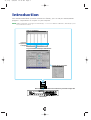
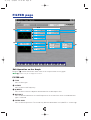
Introduction
With A5000/A4000 Editor (hereafter referred to as Editor), you can edit your A5000/A4000’s
programs, sample banks or samples via your computer.
n Editor for Windows is a plug-in for XGworks(lite). To use Voice Editor for Windows, XGworks(lite) must
be installed beforehand.
Transmit/Receive bulk data or parameter change dataMIDI Cable
A5000/A4000
Memory List Window
Program Edit Window/Sample Edit Window
Program,
sample bank
or sample
Set the effects parameters
2
se_e.qx 9/16/99 12:14 PM Page 2

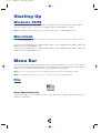
Starting Up
Windows 95/98
If you have a A5000, you can start Editor by starting XGworks and choosing “A5000 Editor”
from the “Plug-in” menu. If you have an A4000, choose “A4000 Editor” instead.
n Set the MIDI Out port appropriately to send the edited data to the A5000/A4000 (Page 7).
Macintosh
n If you are using Voice Editor on a Macintosh computer, open the “Chooser” from the Apple menu and
turn off “Apple Talk.”
If you have an A5000, open the “A5000 Editor” folder in the “YAMAHA Voice Editor” folder and
double-click the “A5000Editor” icon.
If you have an A4000, open the “A4000 Editor” folder in the “YAMAHA Voice Editor” folder and
double-click the “A4000Editor” icon.
Menu Bar
The Menu Bar holds various editing and setup functions/commands in its menus. Click each of
the menu names to open their pull-down menu, and choose the function/command you wish to
apply. Those functions/commands which are unavailable are grayed out.
n The most commonly-used menus in the Menu Bar are available as buttons in Editor's toolbar.
n To use Editor for Windows, refer to the documentation that came with XGworks(lite).
File
Close (Macintosh only)
Closes the window. This is the same as the “Close” box in the Title Bar. (Not effective for the
Memory List Window.)
Macintosh
3
se_e.qx 9/16/99 12:14 PM Page 3

Edit
A5000/A4000 Editor Edit (Edit)
This is the same as the “Edit Window” button in the toolbar (Page 7).
Windows Macintosh
4
se_e.qx 9/16/99 12:14 PM Page 4

Setup (Windows) / MIDI (Macintosh)
A5000/A4000 Editor Setup (Editor Setup)
This is the same as the “Editor Setup” button in the toolbar (Page 7).
A5000/A4000 Editor Receive Memory List (Receive Memory List)
This is the same as the “Receive Memory List” button in the toolbar (Page 7).
OMS Port Setup (Macintosh only)
Opens the OMS Port Setup window for Editor. Refer to the section “OMS Port Setup” (Page 26)
for further details.
OMS MIDI Setup (Macintosh only)
Opens the OMS MIDI Setup window. Refer to the documentation that came with OMS for
further details.
OMS Studio Setup (Macintosh only)
Opens the OMS Studio Setup window. Refer to the documentation that came with OMS for
further details.
Windows Macintosh
5
se_e.qx 9/16/99 12:14 PM Page 5

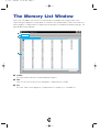
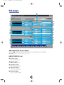
The Memory List Window
When you start Editor, you will first see the Memory List Window consisting of tabs, each
representing the program, sample bank or sample in your A5000/A4000. When you choose to
edit a program, sample bank or sample from the Memory List Window by double-clicking it, the
Edit Window will be opened.
1 Toolbar
This area holds the buttons controlling Editor (Page 7).
2 Tabs
Click any of these to view the list of program, sample bank or sample.
3 List
This area shows all the programs, sample banks or samples as a scrollable list.
1
2
3
6
se_e.qx 9/16/99 12:14 PM Page 6

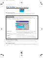
The Toolbar (Memory List Window)
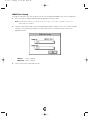
1 “Editor Setup” button
Click this to open the “Editor Setup” dialog and specify the MIDI Out port settings.
“Editor Setup” Dialog
This is where you set up the Editor to allow the transmission of edited data to your
A5000/A4000. Click the [OK] button to apply the settings and quit the dialog. Click the
[Cancel] button to quit without applying the settings.
1 “MIDI Out Port:” ..........................Click this and choose the MIDI Out port. You can use the Voice Editor to
control and edit the device connected to this port. Select the port which
has been assigned to your A5000/A4000 within XGworks(lite).
n If you are using a Macintosh, the MIDI Out Port setting is assigned in the OMS Port Setup. For
further details, see section “OMS Settings.” (Page 27)
2
“MIDI Ch:” ..................................Click this and choose the MIDI Out channel. This is used when
monitoring sounds using the on-screen keyboard in the Edit Windows.
3
“Device No.:” ..............................Click this and choose the MIDI device number of your A5000/A4000.
2 “Receive Memory List” button
Click this to receive all the programs, sample banks or samples data in bulk from your
A5000/A4000.
3 “Edit Window” button
Click this to open the Edit Window for the selected program, sample bank or sample in the
list.
1
2
3
1 2 3
7
se_e.qx 9/16/99 12:14 PM Page 7

8
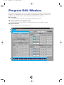
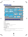
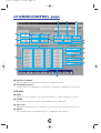
Program Edit Window
The Program Edit Window allows you to edit the parameters related to the A5000/A4000
programs. The edited data are transmitted to the A5000/A4000 via MIDI in realtime. For
information on each parameter, refer to the A5000/A4000 Owner’s Manual.
1 The Toolbar
This area includes the buttons controlling the Edit Window (P.24).
2 “EFFECT/SETUP” and “CONTROL”Tabs
Click the tabs to switch between the “EFFECT/SETUP” and “CONTROL” pages.
3 Keyboard button
Click or drag this to hear the edited results.
1
2
3
se_e.qx 9/16/99 12:14 PM Page 8

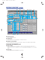
EFFECT/SETUP page
1 PROGRAM LEVEL
Sets the program volume.
2 TRANSPOSE
Sets the pitch of the entire program in semitone intervals.
3 SAMPLE LFO S/H SPEED
Sets the frequency of the LFO S/H waveform. Higher values produce higher speed.
PROGRAM PORTAMENTO unit
4 MODE (MONO)
Selects the PROGRAM PORTAMENTO mode. The mode indicated in parenthesis is
effective only when the sample that uses the PROGRAM PORTAMENTO is in the mono
mode.
5 RATE/TIME
Sets the PROGRAM PORTAMENTO rate or time.
3 @ ! $ % ^ & *
)98
#
1
2
4
6
7
5
9
se_e.qx 9/16/99 12:14 PM Page 9

AD INPUT unit
6 AD INPUT ON/OFF
Turns the AD INPUT function on or off.
7 SOURCE
Sets the input source of the AD INPUT.
8 PAN
Sets the pan position of the input signal via the AD INPUT function. If the source is set to
2Mono, separate settings for INPUT L and INPUT R are available.
9 LEVEL
Sets the levels for OUTPUT 1 and OUTPUT 2, respectively. If the source is set to 2Mono,
separate settings for INPUT L and INPUT R are available.
) OUTPUT
Selects the output destination of the input signal via the AD INPUT function. Two
independent stereo outputs are available for OUTPUT 1 and 2. If the source is set to
2Mono, separate settings are available for INPUT L and INPUT R for both OUTPUT 1 and
2, for a total of four independent stereo outputs.
EFFECT1-3 unit
! CONNECTION
Sets the connections for EFFECT 1, 2 and 3.
@ LEVEL
Sets the input levels for EFFECT 1, 2 and 3.
# DETAIL
Opens the EFFECT 1, 2 and 3 dialog for editing in detail.
$ EFFECT TYPE
Shows the effect types assigned to EFFECT 1, 2 and 3. Click the boxes to see the effect
type list and assign other effects.
% PAN
Sets the output pan positions for EFFECT 1, 2 and 3.
^ WIDTH
Sets the output pan widths for EFFECT 1, 2 and 3.
& LEVEL
Sets the output levels for EFFECT 1, 2 and 3.
* OUTPUT
Selects the output destination for EFFECT 1, 2 and 3. This function is not available for an
effect block which is connected to another effect block.
EFFECT4-6 unit
The same functions are provided for EFFECT 4, 5 and 6 as for EFFECT 1, 2 and 3 above. This
unit is not available for the A4000.
10
se_e.qx 9/16/99 12:14 PM Page 10

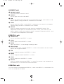
CONTROL page
PROGRAM CONTROL unit
1 DEVICE
Selects the control devices for PROGRAM CONTROLs 1 through 4.
2 FUNCTION
Selects the control functions for PROGRAM CONTROLs 1 through 4.
3 RANGE
Selects the control value ranges for PROGRAM CONTROLs 1 through 4.
4 TYPE
Selects the control methods for PROGRAM CONTROLs 1 through 4.
1 2 3 4 7 8 9 $
5 6 5 6 )! @ % #^
11
se_e.qx 9/16/99 12:14 PM Page 11

CHANNEL SETUP unit
5 CTRL RESET
Determines whether the control value is reset or maintained for each MIDI channel when
the program is switched by a program change message or other mean. Select ON to reset
or NO to maintain. MIDI channels B01 through B16 are not available on the A4000.
6 NOTE ON TYPE
Selects the type of playback which will occur when note-on messages are received for
each MIDI channel. MIDI channels B01 through B16 are not available on the A4000.
PROGRAM LFO unit
7 WAVE
Selects the PROGRAM LFO waveform. The selected waveform is used to modulate the
sound in synchronization with the received MIDI clock and the playback tempo.
8 CYCLE
Selects the note type corresponding to the one PROGRAM LFO cycle.
9 INIT PHASE
Selects the initial phase of the PROGRAM LFO.
) SYNC
Selects the PROGRAM LFO synchronization method. MANUAL allows the PROGRAM LFO
to be synchronized to the specified tempo, and MIDI allows the PROGRAM LFO to be
synchronized to a received MIDI clock.
! TEMPO
Sets the tempo for MANUAL synchronization. This has no effect when MIDI synchronization
is selected.
@ RESET CH
Specifies the MIDI channel via which a received note-on message will initialize the phase
of the PROGRAM LFO when MANUAL synchronization is selected. This has no effect when
MIDI synchronization is selected.
# NOTE
Specifies the note number which will initialize the phase of PROGRAM LFO. This has no
effect when MIDI synchronization is selected.
$ VALUE
Sets the values for STEP 1 through 16 of the step wave waveform. This has no effect on
waves other than the step wave.
% SLOPE
Selects the method by which the step wave steps will be smoothly connected. This has no
effect on waves other than the step wave.
^ TOTAL STEPS
Sets the total number of steps for the step wave. Values for steps beyond the total step
number have no effect.
12
se_e.qx 9/16/99 12:14 PM Page 12

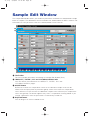
Sample Edit Window
The Sample Edit Window allows you to edit the parameters related to the A5000/A4000 sample
banks or samples. The edited data are transmitted to the A5000/A4000 via MIDI in realtime. For
information on each parameter, refer to the A5000/A4000 Owner’s Manual.
1 The Toolbar
This area includes the buttons controlling the Sample Edit Window (P.24).
2 “MAP/OUT”,“FILTER”,“EG” and “LFO/MIDI/CONTROL” tabs
Click the tabs to switch between the “MAP/OUT”, “FILTER”, “EG” and
“LFO/MIDI/CONTROL” pages.
3 ON/OFF button
Determines whether the sample bank values or the individual sample values will be
effective for each parameter or parameter group. Select ON to make the sample bank
values effective, or OFF to make the inbdividual sample values effective (the sample bank
values are ignored). This button appears only when a sample bank is being edited. If you
change a parameter value this parameter is automatically turned ON.
4 Keyboard button
Click or drag this to hear the edited results.
1
2
3
4
13
se_e.qx 9/16/99 12:14 PM Page 13

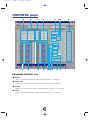
MAP/OUT page
1 LEVEL
Sets the volume level.
2 PAN
Sets the pan position.
3 VELOCITY SENSITIVITY
Sets the velocity sensitivity to control the volume level.
4 POLY/MONO
Selects polyphonic or mono playback.
KEY RANGE unit
5 ORIGINAL
Specifies the original key note number at which the sample sounds at its original pitch. This
cannot be set when a sample bank is being edited.
6 LOW
Sets the lowest key note number for the sample’s key range. This cannot be set when a
sample bank is being edited.
991 9
))
)
&&
& (((
ºº
º ¡¡¡
™™
™ £££
¢¢
¢ ∞∞∞
**
*
!!!
##@
##
#
$$
$
%%%
^^^
2
3
4
5
6
7
8
14
se_e.qx 9/16/99 12:14 PM Page 14

7 HIGH
Sets the highest key note number for the sample’s key range. This cannot be set when a
sample bank is being edited.
8 KEY X-FADE
Turns key crossfade OFF or ON.
PITCH unit
9 COARSE
Adjusts the sample’s pitch in semitone intervals.
) FINE
Fine-tunes the sample’s pitch. This cannot be set when a sample bank is being edited.
! RANDOM
Sets the amount of random pitch variation.
@ FIXED
Determines whether the sample sounds at the same pitch over the entire key range or not.
VELOCITY RANGE unit
# HIGH
Sets the maximum velocity for the velocity range.
$ LOW
Sets the minimum velocity for the velocity range.
% HIGH X-FADE
Sets the crossfade depth at the maximum velocity.
^ LOW X-FADE
Sets the crossfade depth at the minimum velocity.
EXPAND unit
& DETUNE
Sets the detune depth.
* DEPHASE
Sets the dephase depth.
( WIDTH
Sets the pan width for the detuned or dephased sound.
SAMPLE PORTAMENTO unit
º MODE (MONO)
Selects the sample portamento mode. The mode in parentheses is effective only when the
sample or sample bank is set to the mono mode.
¡ RATE/TIME
Sets the portamento rate or time.
15
se_e.qx 9/16/99 12:14 PM Page 15

LEVEL SCALING unit
™ BREAK POINT
Sets the note number for level scaling BREAK POINT 1, 2.
£ LEVEL
Sets the BREAK POINT 1, 2 volume level.
OUTPUT unit
¢ LEVEL
Sets the OUTPUT 1, 2 volume level.
∞ OUTPUT
Selects the output destination of the sample or sample bank. Two independent stereo
outputs are available for OUTPUT 1 and 2.
16
se_e.qx 9/16/99 12:14 PM Page 16

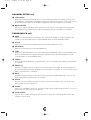
FILTER page
Edit Operation on the Graph
Drag the “■” marker toward the arrow mark to set the parameter on the graph.
n “■” markers may be overlapped sometimes.
FILTER unit
1 TYPE
Sets the filter type.
2 CUTOFF
Sets the filter cutoff frequency.
3 Q/WIDTH
Sets the filter resonance depth or band width for the band pass filter.
4 DISTANCE
Sets the distance between the cutoff frequencies of the two filters when a combined filter
type is selected.
5 FILTER GAIN
Sets the filter output level. The sound may become distorted if the Q/WIDTH is set too high.
1
8
6
7
@@
@ #
222
333
444
999
)))
!!!
555
17
se_e.qx 9/16/99 12:14 PM Page 17

6 VELOCITY→CUTOFF
Determines how the cutoff frequency changes in response to velocity.
7 VELOCITY→Q/WIDTH
Determines how the Q/WIDTH value changes in response to velocity.
EQ unit
8 TYPE
Sets the EQ type.
9 FREQUENCY
Sets the EQ frequency point.
) GAIN
Sets the gain at the selected frequency point.
! WIDTH
Sets the band width. This may not be available for some filter types.
FILTER SCALING unit
@ BREAK POINT
Sets the filter scaling BREAK POINT 1, 2 note.
# CUTOFF
Sets the amount of cutoff increase or decrease at BREAK POINT 1, 2.
18
se_e.qx 9/16/99 12:14 PM Page 18

EG page
Edit Operation on the Graph
Drag the “■” marker toward the arrow mark to set the parameter on the graph.
n “■” markers may be overlapped sometimes.
AMPLITUDE EG unit
1 ATTACK RATE
Sets the attack rate.
2 DECAY RATE
Sets the decay rate.
3 RELEASE RATE
Sets the release rate.
4 SUSTAIN LEVEL
Sets the sustain level.
5 ATTACK MODE
Sets the attack mode.
!!
1
2
3
8
9
)
(
º
¡
5
4
6
7
!
@@
@
##
#
$$
$
^
%
&
*
™™
™
££
£
¢¢
¢
∞∞
∞
¶
§
•
ª
19
se_e.qx 9/16/99 12:14 PM Page 19

6 RATE SCALING
Determines how the amplitude EG rates vary according to the note played.
7 VELOCITY→RATE
Determines how the amplitude EG rates vary in response to the velocity of the played note.
FILTER EG unit
8 ATTACK RATE
Sets the rate at which the cutoff frequency moves from its initial level (at note on) to the
attack level.
9 DECAY RATE
Sets the rate at which the cutoff frequency moves from the attack level to the sustain level.
) RELEASE RATE
Sets the rate at which the cutoff frequency moves from the sustain level to the release level
following note off.
! INIT LEVEL
Sets the cutoff frequency offset value at the time of note on.
@ ATTACK LEVEL
Sets the cutoff frequency offset value at the attack level.
# SUSTAIN LEVEL
Sets the cutoff frequency offset value at the sustain level.
$ RELEASE LEVEL
Sets the cutoff frequency offset value at the release level.
% RATE SCALING
Determines how the filter EG rates vary according to the note played.
^ VELOCITY→RATE
Determines how the filter EG rates vary in response to the velocity of the played note.
& VELOCITY→ATTACK LEVEL
Sets the first velocity-sensitivity value for the filter EG’s initial level and attack level.
* VELOCITY→LEVEL
Sets the general velocity sensitivity for all filter EG levels.
PITCH EG unit
( ATTACK RATE
Sets the rate at which the pitch moves from its initial level (at note on) to the attack level.
º DECAY RATE
Sets the rate at which the pitch moves from the attack level to the sustain level.
¡ RELEASE RATE
Sets the rate at which the pitch moves from the sustain level to the release level following
note off.
™ INIT LEVEL
Sets the pitch offset value at the time of note on.
20
se_e.qx 9/16/99 12:14 PM Page 20
La pagina si sta caricando...
La pagina si sta caricando...
La pagina si sta caricando...
La pagina si sta caricando...
La pagina si sta caricando...
La pagina si sta caricando...
La pagina si sta caricando...
-
 1
1
-
 2
2
-
 3
3
-
 4
4
-
 5
5
-
 6
6
-
 7
7
-
 8
8
-
 9
9
-
 10
10
-
 11
11
-
 12
12
-
 13
13
-
 14
14
-
 15
15
-
 16
16
-
 17
17
-
 18
18
-
 19
19
-
 20
20
-
 21
21
-
 22
22
-
 23
23
-
 24
24
-
 25
25
-
 26
26
-
 27
27


Yamaha A4000 Manuale del proprietario
- Categoria
- Strumenti musicali
- Tipo
- Manuale del proprietario
- Questo manuale è adatto anche per
in altre lingue
- English: Yamaha A4000 Owner's manual
- français: Yamaha A4000 Le manuel du propriétaire
- español: Yamaha A4000 El manual del propietario
- Deutsch: Yamaha A4000 Bedienungsanleitung
- русский: Yamaha A4000 Инструкция по применению
- Nederlands: Yamaha A4000 de handleiding
- português: Yamaha A4000 Manual do proprietário
- dansk: Yamaha A4000 Brugervejledning
- čeština: Yamaha A4000 Návod k obsluze
- polski: Yamaha A4000 Instrukcja obsługi
- svenska: Yamaha A4000 Bruksanvisning
- Türkçe: Yamaha A4000 El kitabı
- suomi: Yamaha A4000 Omistajan opas
- română: Yamaha A4000 Manualul proprietarului