Sony MEX-BT4000U Manuale del proprietario
- Categoria
- Microfoni
- Tipo
- Manuale del proprietario

FRONT
AUDIO OUT
REAR / SUB
AUDIO OUT
*
4
REMOTE
IN
*
5
MIC IN
*
6
Let op
Installeer dit apparaat in het dashboard van de auto
omdat de achterkant van het apparaat tijdens gebruik
heet kan worden.
Dit apparaat is ontworpen voor gebruik op een
auto-accu van 12 V gelijkstroom, negatieve aarde.
Zorg ervoor dat de draden niet onder een schroef of
tussen bewegende onderdelen (bv. rail van de autostoel)
terechtkomen.
Voordat u de aansluitingen maakt, moet u het contact
uitzetten om kortsluiting te vermijden.
Sluit de voedingskabel aan op het apparaat en de
luidsprekers voordat u de kabel aansluit op de
hulpvoedingsaansluiting.
Sluit alle aardingskabels op een
gemeenschappelijk aardpunt aan.
Voorzie niet-aangesloten kabels om veiligheidsredenen
altijd van isolatietape.
Opmerkingen bij de voedingskabel (geel)
Wanneer u dit apparaat aansluit samen met andere
componenten, moet het vermogen van de aangesloten
autostroomkring groter zijn dan de som van de
zekeringen van elke component afzonderlijk.
Wanneer het vermogen ontoereikend is, moet u het
apparaat rechtstreeks aansluiten op de accu.
Onderdelenlijst
De nummers in de afbeelding verwijzen naar die in de
montage-aanwijzingen.
De beugel en de beschermende rand worden
bevestigd op het apparaat voordat dit wordt verzonden.
Voordat u het apparaat plaatst, moet u de
ontgrendelingssleutels gebruiken om de beugel te
verwijderen van het apparaat. Zie "De beschermende
rand en de beugel verwijderen ()" aan de achterzijde
van dit vel voor meer informatie.
Bewaar de ontgrendelingssleutels voor
toekomstig gebruik omdat u deze ook nodig hebt
om het apparaat uit de auto te verwijderen.
Let op
Houd de beugel voorzichtig vast zodat u uw vingers
niet verwondt.
Greep
Opmerking
Voordat u het apparaat installeert, moet u de grepen aan beide zijden
van de beugel 2 mm naar binnen buigen. Als de grepen recht zijn of
naar buiten gebogen, kan het apparaat niet goed worden bevestigd en
kan dit losschieten.
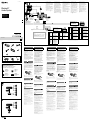
Voorbeeldaansluitingen
Opmerkingen (-
A
)
Sluit eerst de aarddraad aan voordat u de versterker aansluit.
U hoort de pieptoon alleen als de ingebouwde versterker wordt
gebruikt.
Aansluitschema
Naar AMP REMOTE IN van een optionele
eindversterker
Deze aansluiting is alleen bedoeld voor versterkers. Door een ander
systeem aan te sluiten kan het apparaat worden beschadigd.
Naar het interface-snoer van een autotelefoon
Waarschuwing
Indien u een elektrische antenne hebt zonder relaiskast,
kan het aansluiten van dit apparaat met de bijgeleverde
voedingskabel de antenne beschadigen.
Opmerkingen over de bedienings- en voedingskabels
De bedieningskabel voor de elektrische antenne (blauw) levert +12 V
gelijkstroom wanneer u de tuner inschakelt of de AF (Alternative
Frequency) of TA (Traffic Announcement) functie activeert.
Wanneer uw auto is uitgerust met een FM/MW/LW-antenne in de
achterruit/zijruit, moet u de bedieningskabel voor de elektrische
antenne (blauw) of de hulpvoedingskabel (rood) aansluiten op de
voedingsingang van de bestaande antenneversterker. Raadpleeg uw
dealer voor meer details.
Met dit apparaat is het niet mogelijk een elektrische antenne zonder
relaiskast te gebruiken.
Instandhouden van het geheugen
Zolang de gele voedingskabel is aangesloten, blijft de stroomvoorziening
van het geheugen intact, ook wanneer het contact van de auto wordt
uitgeschakeld.
Opmerkingen betreffende het aansluiten van de luidsprekers
Zorg dat het apparaat is uitgeschakeld, alvorens de luidsprekers aan
te sluiten.
Gebruik luidsprekers met een impedantie van 4 tot 8 ohm en let op dat
die het vermogen van de versterker kunnen verwerken. Als u dit niet
doet, kunnen de luidsprekers ernstig beschadigd raken.
Verbind in geen geval de aansluitingen van de luidsprekers met het
chassis van de auto en sluit de aansluitingen van de rechter- en
linkerluidspreker niet op elkaar aan.
Verbind de aarddraad van dit apparaat niet met de negatieve (–)
aansluiting van de luidspreker.
Probeer nooit de luidsprekers parallel aan te sluiten.
Sluit geen actieve luidsprekers (met ingebouwde versterkers) aan op
de luidsprekeraansluiting van dit apparaat. Dit zal leiden tot
beschadiging van de actieve luidsprekers. Sluit dus altijd uitsluitend
luidsprekers zonder ingebouwde versterker aan.
Om defecten te vermijden mag u de bestaande luidsprekerbedrading
in uw auto niet gebruiken wanneer er een gemeenschappelijke
negatieve (–) draad is voor de rechter- en linkerluidsprekers.
Verbind de luidsprekerdraden niet met elkaar.
Opmerking over aansluiten
Als de luidspreker en versterker niet correct zijn aangesloten, wordt
"FAILURE" in het display weergegeven. In dit geval moet u zorgen dat de
luidspreker en versterker correct zijn aangesloten.
Précautions
Installez cet appareil sur le tableau de bord de la
voiture, car l’arrière de l’appareil chauffe en cours
d’utilisation.
Cet appareil est conçu pour fonctionner uniquement
sur un courant continu de 12 V avec masse négative.
Evitez de coincer les câbles sous des vis ou dans des
pièces mobiles (par exemple, armature de siège).
Avant d’effectuer des raccordements, éteignez le moteur
pour éviter les courts-circuits.
Branchez le câble d’alimention sur l’appareil et les
haut-parleurs avant de le brancher sur le connecteur
d’alimentation auxiliaire.
Rassemblez tous les câbles de mise à la masse en
un point de masse commun.
Veillez à isoler tout câble lâche non raccordé avec du
ruban isolant.
Remarques sur le câble d’alimentation (jaune)
Lorsque cet appareil est raccordé à d’autres équipements
stéréo, la valeur nominale du circuit raccordé du
véhicule doit être supérieure à la somme des fusibles de
chaque élément.
Si aucun circuit de la voiture n’est assez puissant,
raccordez directement l’appareil à la batterie.
Liste des composants
Les numéros de la liste correspondent à ceux des
instructions.
Le support et le tour de protection sont fixés à
l’appareil en usine. Avant le montage de l’appareil,
utilisez les clés de déblocage pour détacher le
support de l’appareil. Pour de plus amples
informations, reportez-vous à la section « Retrait du
tour de protection et du support () » au verso de la
feuille.
Conservez les clés de déblocage pour une
utilisation ultérieure car vous en aurez également
besoin pour retirer l’appareil de votre véhicule.
Avertissement
Manipulez le support avec soin pour éviter de vous
blesser aux doigts.
Loquet
Remarque
Avant l’installation, assurez-vous que les loquets des deux côtés du
support sont bien pliés de 2 mm vers l’intérieur. Si les loquets sont
droits ou pliés vers l’extérieur, l’appareil ne peut pas être fixé solidement
et peut se détacher.
Exemple de raccordement
Remarques (-
A
)
Raccordez d’abord le câble de mise à la masse avant de connecter
l’amplificateur.
L’alarme est émise uniquement lorsque l’amplificateur intégré est
utilisé.
Schéma de raccordement
Vers la prise AMP REMOTE IN d’un amplificateur
de puissance facultatif
Ce raccordement existe seulement pour les amplificateurs. Le
raccordement à tout autre système peut endommager l’appareil.
Vers le câble d'interface d’un téléphone de
voiture
Avertissement
Si vous disposez d’une antenne électrique sans boîtier de
relais, le branchement de cet appareil au moyen du
cordon d’alimentation fourni risque d’endommager
l’antenne.
Remarques sur les câbles de commande et d’alimentation
Le câble de commande d’antenne électrique (bleu) fournit du courant
continu de +12 V lorsque vous mettez le tuner sous tension ou lorsque
vous activez la fonction AF (fréquence alternative) ou TA (informations
de circulation).
Lorsque votre voiture est équipée d’une antenne FM/MW (PO)/LW (GO)
intégrée dans la vitre arrière/latérale, raccordez le câble de commande
d’antenne électrique (bleu) ou le câble d’alimentation des accessoires
(rouge) à la borne d'alimentation de l’amplificateur d’antenne
existant. Pour plus de détails, consultez votre revendeur.
Une antenne électrique sans boîtier de relais ne peut pas être utilisée
avec cet appareil.
Raccordement pour la conservation de la mémoire
Lorsque le câble d’alimentation jaune est raccordé, le circuit de la
mémoire est alimenté en permanence même si la clé de contact est en
position d’arrêt.
Remarques sur le raccordement des haut-parleurs
Avant de raccorder les haut-parleurs, mettre l’appareil hors tension.
Utiliser des haut-parleurs ayant une impédance de 4 à 8 ohms et une
capacité adéquate sous peine de les endommager.
Ne pas raccorder les bornes du système de haut-parleurs au châssis de
la voiture et ne pas connecter les bornes des haut-parleurs droit à
celles des haut-parleurs gauche.
Ne pas raccorder le câble de mise à la masse de cet appareil à la borne
négative (–) du haut-parleur.
Ne pas tenter de raccorder les haut-parleurs en parallèle.
Connecter uniquement des haut-parleurs passifs. La connexion de
haut-parleurs actifs (avec des amplificateurs intégrés) aux bornes des
haut-parleurs pourrait endommager l’appareil.
Pour éviter tout problème de fonctionnement, n’utilisez pas les câbles
des haut-parleurs intégrés (–) installés dans votre voiture si l’appareil
dispose d’un câble négatif commun pour les haut-parleurs droit et
gauche.
Ne raccordez pas entre eux les cordons des haut-parleurs de l’appareil.
Remarque sur le raccordement
Si les haut-parleurs et l’amplificateur ne sont pas raccordés
correctement, le message « FAILURE » s’affiche. Dans ce cas, assurez-vous
que les haut-parleurs et l’amplificateur sont raccordés correctement.
Warnhinweise
Installieren Sie das Gerät unbedingt im
Armaturenbrett des Fahrzeugs, denn die Rückseite des
Geräts erwärmt sich bei Betrieb.
Dieses Gerät ist ausschließlich für den Betrieb bei 12 V
Gleichstrom (negative Erdung) bestimmt.
Achten Sie darauf, dass die Kabel nicht unter einer
Schraube oder zwischen beweglichen Teilen wie
z. B. in einer Sitzschiene eingeklemmt werden.
Schalten Sie, bevor Sie irgendwelche Anschlüsse
vornehmen, die Zündung des Fahrzeugs aus, um
Kurzschlüsse zu vermeiden.
Verbinden Sie das Stromversorgungskabel mit dem
Gerät und den Lautsprechern, bevor Sie es mit dem
Hilfsstromanschluss verbinden.
Schließen Sie alle Erdungskabel an einen
gemeinsamen Massepunkt an.
Aus Sicherheitsgründen müssen alle losen, nicht
angeschlossenen Drähte mit Isolierband abgeklebt
werden.
Hinweise zum Stromversorgungskabel (gelb)
Wenn Sie dieses Gerät zusammen mit anderen
Stereokomponenten anschließen, muss der
Autostromkreis, an den die Geräte angeschlossen sind,
eine höhere Leistung aufweisen als die Summe der
Sicherungen der einzelnen Komponenten.
Wenn kein Autostromkreis eine so hohe Leistung
aufweist, schließen Sie das Gerät direkt an die Batterie
an.
Teileliste
Die Nummern in der Liste sind dieselben wie im
Erläuterungstext.
Die Halterung und die Schutzumrandung
werden vor dem Ausliefern am Gerät angebracht. Bevor
Sie das Gerät montieren, nehmen Sie die Halterung
mithilfe der Löseschlüssel bitte vom Gerät ab.
Einzelheiten dazu finden Sie unter „Abnehmen der
Schutzumrandung und der Halterung ()“ auf der
Rückseite dieses Blattes.
Bewahren Sie die Löseschlüssel für den
späteren Gebrauch auf. Sie werden
z. B. benötigt, wenn Sie das Gerät aus dem
Fahrzeug ausbauen wollen.
Vorsicht
Seien Sie beim Umgang mit der Halterung vorsichtig,
damit Sie sich nicht die Hände verletzen.
Verriegelung
Hinweis
Vergewissern Sie sich vor dem Installieren, dass die Verriegelungen an
beiden Seiten der Halterung um 2 mm nach innen gebogen sind.
Wenn die Verriegelungen gerade oder nach außen gebogen sind, lässt
sich das Gerät nicht sicher installieren und kann herausspringen.
Anschlussbeispiel
Hinweise (-
A
)
Schließen Sie unbedingt zuerst das Massekabel an, bevor Sie den
Verstärker anschließen.
Der Warnton wird nur ausgegeben, wenn der integrierte Verstärker
verwendet wird.
Anschlussdiagramm
An AMP REMOTE IN des gesondert erhältlichen
Endverstärkers
Dieser Anschluss ist ausschließlich für Verstärker gedacht. Schließen
Sie nichts anderes daran an. Andernfalls kann das Gerät beschädigt
werden.
An Schnittstellenkabel eines Autotelefons
Warnung
Wenn Sie eine Motorantenne ohne Relaiskästchen
verwenden, kann durch Anschließen dieses Geräts mit
dem mitgelieferten Stromversorgungskabel die
Antenne beschädigt werden.
Hinweise zu den Steuer- und Stromversorgungsleitungen
Die Motorantennen-Steuerleitung (blau) liefert +12 V Gleichstrom,
wenn Sie den Tuner einschalten oder die AF- (Alternativfrequenzsuche)
oder die TA-Funktion (Verkehrsdurchsagen) aktivieren.
Wenn das Fahrzeug mit einer in der Heck-/Seitenfensterscheibe
integrierten FM (UKW)/MW/LW-Antenne ausgestattet ist, schließen Sie
die Motorantennen-Steuerleitung (blau) oder die
Zubehörstromversorgungsleitung (rot) an den
Stromversorgungsanschluss des vorhandenen Antennenverstärkers
an. Näheres dazu erfahren Sie bei Ihrem Händler.
Es kann nur eine Motorantenne mit Relaiskästchen angeschlossen
werden.
Stromversorgung des Speichers
Wenn die gelbe Stromversorgungsleitung angeschlossen ist, wird der
Speicher stets (auch bei ausgeschalteter Zündung) mit Strom versorgt.
Hinweise zum Lautsprecheranschluss
Schalten Sie das Gerät aus, bevor Sie die Lautsprecher anschließen.
Verwenden Sie Lautsprecher mit einer Impedanz zwischen 4 und 8
Ohm und ausreichender Belastbarkeit. Ansonsten können die
Lautsprecher beschädigt werden.
Verbinden Sie die Lautsprecheranschlüsse nicht mit dem
Wagenchassis und verbinden Sie auch nicht die Anschlüsse des
rechten mit denen des linken Lautsprechers.
Verbinden Sie die Masseleitung dieses Geräts nicht mit dem negativen
(–) Lautsprecheranschluss.
Versuchen Sie nicht, Lautsprecher parallel anzuschließen.
An die Lautsprecheranschlüsse dieses Geräts dürfen nur
Passivlautsprecher angeschlossen werden. Schließen Sie keine
Aktivlautsprecher (Lautsprecher mit eingebauten Verstärkern) an, da
das Gerät sonst beschädigt werden könnte.
Um Fehlfunktionen zu vermeiden, verwenden Sie nicht die im
Fahrzeug installierten, integrierten Lautsprecherleitungen, wenn am
Ende eine gemeinsame negative (–) Leitung für den rechten und den
linken Lautsprecher verwendet wird.
Verbinden Sie nicht die Lautsprecherkabel des Geräts miteinander.
Hinweis zum Anschließen
Wenn Lautsprecher und Verstärker nicht richtig angeschlossen sind,
erscheint „FAILURE“ im Display. Vergewissern Sie sich in diesem Fall, dass
Lautsprecher und Verstärker richtig angeschlossen sind.
Attenzione
Assicurarsi di installare l’apparecchio nel cruscotto
dell’auto, poiché la parte posteriore dell’apparecchio
stesso si surriscalda durante l’uso.
Questo apparecchio è stato progettato per l’uso solo a
12 V CC con massa negativa.
Evitare che i cavi rimangano bloccati da una vite o
incastrati nelle parti mobili (ad esempio nelle guide
scorrevoli dei sedili).
Prima di effettuare i collegamenti, spegnere il motore
dell’automobile onde evitare di causare cortocircuiti.
Collegare il cavo di alimentazione all’apparecchio e
ai diffusori prima di collegarlo al connettore di
alimentazione ausiliaria.
Portare tutti i cavi di messa a terra a un punto di
massa comune.
Per sicurezza, assicurarsi di isolare qualsiasi cavo non
collegato utilizzando del nastro adesivo.
Note sul cavo di alimentazione (giallo)
Se questo apparecchio viene collegato in combinazione
con altri componenti stereo, la potenza nominale dei
circuiti dell’automobile deve essere superiore a quella
prodotta dalla somma dei fusibili di ciascun
componente.
Se la potenza nominale dei circuiti dell’automobile non
è sufficiente, collegare l’apparecchio direttamente alla
batteria.
Elenco dei componenti
I numeri nella lista corrispondono a quelli riportati
nelle istruzioni.
La staffa e la cornice protettiva vengono applicati
all’unità in fabbrica. Prima di installare l’unità,
utilizzare le chiavette di rilascio per rimuovere la
staffa dall’apparecchio. Per ulteriori informazioni,
vedere “Rimozione della staffa e della cornice protettiva
()” sul lato opposto del foglio.
Conservare le chiavette di rilascio per un uso
futuro in quanto sono necessarie per rimuovere
l’unità dall’auto.
Attenzione
Maneggiare la staffa con cautela per evitare di ferirsi le
mani.
Fermo
Nota
Prima di installare l’unità, accertarsi di ripiegare i fermi presenti su
entrambi i lati della staffa verso l’interno di 2 mm. Se i fermi sono
diritti o ripiegati verso l’esterno, l’apparecchio non verrà installato in
modo sicuro e potrebbe fuoriuscire.
Esempio di collegamento
Note (-
A
)
Assicurarsi di collegare il cavo di terra prima di collegare l’apparecchio
all’amplificatore.
L’allarme viene emesso solo se è in uso l’amplificatore incorporato.
Schema di collegamento
A AMP REMOTE IN di un amplificatore di
potenza opzionale
Questo collegamento è riservato esclusivamente agli amplificatori.
Non collegare un tipo di sistema diverso onde evitare di causare
danni all’apparecchio.
Al cavo di interfaccia di un telefono per auto
Avvertenza
Quando si collega l’apparecchio con il cavo di
alimentazione in dotazione , si potrebbe danneggiare
l’antenna elettrica se questa non dispone di scatola a relè.
Note sui cavi di controllo e di alimentazione
Il cavo (blu) di controllo dell’antenna elettrica fornisce alimentazione
pari a +12 V CC quando si attiva il sintonizzatore oppure la funzione
TA (notiziario sul traffico) o AF (frequenza alternativa).
Se l’automobile è dotata di antenna FM/MW/LW incorporata nel vetro
posteriore/laterale, collegare il cavo (blu) di controllo dell’antenna
elettrica o il cavo (rosso) di ingresso dell’alimentazione accessoria al
terminale di alimentazione del preamplificatore dell’antenna
esistente. Per ulteriori informazioni, consultare il proprio fornitore.
Non è possibile usare un’antenna elettrica senza scatola a relè con
questo apparecchio.
Collegamento per la conservazione della memoria
Quando il cavo di ingresso alimentazione giallo è collegato, viene
sempre fornita alimentazione al circuito di memoria anche quando
l’interruttore di accensione è spento.
Note sul collegamento dei diffusori
Prima di collegare i diffusori spegnere l’apparecchio.
Usare diffusori di impedenza compresa tra 4 e 8 ohm e con capacità di
potenza adeguata, altrimenti i diffusori potrebbero venire
danneggiati.
Non collegare i terminali del sistema diffusori al telaio dell’auto e non
collegare i terminali del diffusore destro a quelli del diffusore sinistro.
Non collegare il cavo di terra di questo apparecchio al terminale
negativo (–) del diffusore.
Non collegare i diffusori in parallelo.
Assicurarsi di collegare soltanto diffusori passivi, poiché il
collegamento di diffusori attivi, dotati di amplificatori incorporati, ai
terminali dei diffusori potrebbe danneggiare l’apparecchio.
Per evitare problemi di funzionamento, non utilizzare i cavi dei
diffusori incorporati installati nell’automobile se l’apparecchio
condivide un cavo comune negativo (–) per i diffusori destro e sinistro.
Non collegare fra loro i cavi dei diffusori dell’apparecchio.
Nota sui collegamenti
Se l’amplificatore e il diffusore non sono collegati correttamente,
“FAILURE” viene visualizzato nel display. In tal caso, accertarsi che
l’amplificatore e il diffusore siano collegati correttamente.
Cautions
Be sure to install this unit in the dashboard of the car
as the rear side of the unit becomes hot during use.
This unit is designed for negative ground (earth) 12 V
DC operation only.
Do not get the leads under a screw, or caught in moving
parts (e.g. seat railing).
Before making connections, turn the car ignition off to
avoid short circuits.
Connect the power supply lead to the unit and
speakers before connecting it to the auxiliary power
connector.
Run all ground (earth) leads to a common ground
(earth) point.
Be sure to insulate any loose unconnected leads with
electrical tape for safety.
Notes on the power supply lead (yellow)
When connecting this unit in combination with other
stereo components, the connected car circuit’s rating
must be higher than the sum of each component’s fuse.
When no car circuits are rated high enough, connect
the unit directly to the battery.
Parts list
The numbers in the list are keyed to those in the
instructions.
The bracket and the protection collar are
attached to the unit before shipping. Before mounting
the unit, use the release keys to remove the bracket
from the unit. For details, see “Removing the
protection collar and the bracket ()” on the reverse
side of the sheet.
Keep the release keys for future use as they are
also necessary if you remove the unit from your
car.
Caution
Handle the bracket carefully to avoid injuring your
fingers.
Catch
Note
Before installing, make sure that the catches on both sides of the bracket
are bent inwards 2 mm (
3
/32 in). If the catches are straight or bent
outwards, the unit will not be installed securely and may spring out.
Connection example
Notes (-
A
)
Be sure to connect the ground (earth) lead before connecting the
amplifier.
The alarm will only sound if the built-in amplifier is used.
Connection diagram
To AMP REMOTE IN of an optional power
amplifier
This connection is only for amplifiers. Connecting any other system
may damage the unit.
To the interface cable of a car telephone
Warning
If you have a power antenna (aerial) without a relay box,
connecting this unit with the supplied power supply lead
may damage the antenna (aerial).
Notes on the control and power supply leads
The power antenna (aerial) control lead (blue) supplies +12 V DC when
you turn on the tuner, or when you activate the AF (Alternative
Frequency) or TA (Traffic Announcement) function.
When your car has built-in FM/MW/LW antenna (aerial) in the rear/
side glass, connect the power antenna (aerial) control lead (blue) or
the accessory power supply lead (red) to the power terminal of the
existing antenna (aerial) booster. For details, consult your dealer.
A power antenna (aerial) without a relay box cannot be used with this
unit.
Memory hold connection
When the yellow power supply lead is connected, power will always be
supplied to the memory circuit even when the ignition switch is turned
off.
Notes on speaker connection
Before connecting the speakers, turn the unit off.
Use speakers with an impedance of 4 to 8 ohms, and with adequate
power handling capacities to avoid its damage.
Do not connect the speaker terminals to the car chassis, or connect the
terminals of the right speakers with those of the left speaker.
Do not connect the ground (earth) lead of this unit to the negative (–)
terminal of the speaker.
Do not attempt to connect the speakers in parallel.
Connect only passive speakers. Connecting active speakers (with
built-in amplifiers) to the speaker terminals may damage the unit.
To avoid a malfunction, do not use the built-in speaker leads installed
in your car if the unit shares a common negative (–) lead for the right
and left speakers.
Do not connect the unit’s speaker leads to each other.
Note on connection
If speaker and amplifier are not connected correctly, “FAILURE” appears
in the display. In this case, make sure the speaker and amplifier are
connected correctly.
× 2
4
Yellow
Gelb
Jaune
Giallo
Geel
continuous power supply
permanente Stromversorgung
alimentation continue
alimentazione continua
continu voeding
7
Red
Rot
Rouge
Rosso
Rood
switched power supply
geschaltete Stromversorgung
alimentation commutée
alimentazione commutata
geschakelde voeding
5
Blue
Blau
Bleu
Blu
Blauw
power antenna (aerial) control
Motorantennensteuerung
commande d'antenne électrique
comando dell’antenna elettrica
elektrische antenne
8
Black
Schwarz
Noir
Nero
Zwart
ground (earth)
Masse
masse
terra
aarding
6
Orange/White
Orangeweiß
gestreift
Rayé orange/
blanc
Arancione/
bianco
Oranje/wit
switched illumination power
supply
geschaltete
Beleuchtungsstromversorgung
alimentation de l’éclairage
commuté
alimentazione illuminazione
commutata
geschakelde voeding voor
verlichting
Negative polarity positions 2, 4, 6, and 8 have striped leads.
An den negativ gepolten Positionen 2, 4, 6 und 8 befinden sich gestreifte Adern.
Les positions de polarité négative 2, 4, 6 et 8 sont dotées de cordons rayés.
Le posizioni a polarità negativa 2, 4, 6 e 8 hanno cavi rigati.
De posities voor negatieve polariteit (2, 4, 6 en 8) hebben gestreepte kabels.
1
Purple
Violett
Violet
Viola
Paars
+
Speaker, Rear, Right
Lautsprecher hinten rechts
Haut-parleur, arrière, droit
Diffusore, posteriore, destro
Luidspreker, achter, rechts
5
White
Weiß
Blanc
Bianco
Wit
+
Speaker, Front, Left
Lautsprecher vorne links
Haut-parleur, avant, gauche
Diffusore, anteriore, sinistro
Luidspreker, voor, links
2 –
Speaker, Rear, Right
Lautsprecher hinten rechts
Haut-parleur, arrière, droit
Diffusore, posteriore, destro
Luidspreker, achter, rechts
6 –
Speaker, Front, Left
Lautsprecher vorne links
Haut-parleur, avant, gauche
Diffusore, anteriore, sinistro
Luidspreker, voor, links
3
Gray
Grau
Gris
Grigio
Grijs
+
Speaker, Front, Right
Lautsprecher vorne rechts
Haut-parleur, avant, droit
Diffusore, anteriore, destro
Luidspreker, voor, rechts
7
Green
Grün
Vert
Verde
Groen
+
Speaker, Rear, Left
Lautsprecher hinten links
Haut-parleur, arrière, gauche
Diffusore, posteriore, sinistro
Luidspreker, achter, links
4 –
Speaker, Front, Right
Lautsprecher vorne rechts
Haut-parleur, avant, droit
Diffusore, anteriore, destro
Luidspreker, voor, rechts
8 –
Speaker, Rear, Left
Lautsprecher hinten links
Haut-parleur, arrière, gauche
Diffusore, posteriore, sinistro
Luidspreker, achter, links
Fuse (10 A)
Sicherung (10 A)
Fusible (10 A)
Fusibile (10 A)
Zekering (10 A)
from the car’s power connector
vom Stromanschluss des Fahrzeugs
du connecteur d’alimentation de la voiture
dal connettore di alimentazione dell’auto
van de autovoedingsaansluiting
See “Power connection diagram” on the reverse side for details.
Näheres dazu finden Sie im „Stromanschlussdiagramm“. Blättern Sie
dazu bitte um.
Voir le « Schéma de raccordement d’alimentation » au verso pour plus
de détails.
Per ulteriori informazioni, vedere “Diagramma dei collegamenti di
alimentazione” che si trova sul retro.
Zie "Voedingsaansluitschema" op de achterkant voor meer details.
from the car’s speaker connector
vom Lautsprecheranschluss des Fahrzeugs
du connecteur de haut-parleur de la voiture
dal connettore dei diffusori dell’auto
van de autoluidsprekeraansluiting
*
2
from car antenna (aerial)
von Autoantenne
de l’antenne de la voiture
dall’antenna dell’auto
van een auto-antenne
*
3
*
7
*
3
*
1
Speaker impedance: 4 – 8 ohms × 4
*
2
Note for the antenna (aerial) connecting
If your car antenna (aerial) is an ISO (International
Organization for Standardization) type, use the
supplied adaptor to connect it. First connect
the car antenna (aerial) to the supplied adaptor,
then connect it to the antenna (aerial) jack of the
master unit.
*
3
RCA pin cord (not supplied)
*
4
AUDIO OUT can be switched SUB or REAR. For
details, see the supplied Operating Instructions.
*
5
Separate adaptor may be required.
*
6
Whether in use or not, route the microphone input
cord such that it does not interfere with driving.
Secure the cord with a clamp, etc., if it is installed
around your feet.
*
7
For details on installing the microphone, see
“Installing the microphone ()” on the reverse
side.
*
1
Lautsprecherimpedanz: 4 – 8 Ohm × 4
*
2
Hinweis zum Anschließen der Antenne
Wenn Ihre Autoantenne der ISO-Norm
(Internationale Normungsgemeinschaft)
entspricht, schließen Sie sie mithilfe des
mitgelieferten Adapters an. Verbinden Sie
zuerst die Autoantenne mit dem mitgelieferten
Adapter und verbinden Sie diesen dann mit der
Antennenbuchse des Hauptgeräts.
*
3
Cinchkabel (nicht mitgeliefert)
*
4
AUDIO OUT kann zwischen SUB und REAR
umgeschaltet werden. Näheres hierzu finden Sie in
der mitgelieferten Bedienungsanleitung.
*
5
Möglicherweise ist ein separater Adapter
erforderlich.
*
6
Führen Sie das Mikrofoneingangskabel so, dass es
beim Fahren nicht hinderlich ist, unabhängig
davon, ob es gerade in Gebrauch ist oder nicht.
Sichern Sie das Kabel mit einer Kabelklemme usw.,
falls es durch den Fußraum geführt werden muss.
*
7
Erläuterungen zur Installation des Mikrofons
finden Sie unter „Installieren des Mikrofons ()“
auf der Rückseite.
*
1
Impédance des haut-parleurs : 4 – 8 ohms × 4
*
2
Remarque sur le raccordement de l’antenne
Si votre antenne de voiture est de type ISO
(Organisation internationale de normalisation),
utilisez l’adaptateur fourni pour la raccorder.
Raccordez d’abord l’antenne de voiture à
l’adaptateur fourni et, ensuite, à la prise d’antenne
de l’appareil principal.
*
3
Cordon à broche RCA (non fourni)
*
4
AUDIO OUT peut être commuté sur SUB ou REAR.
Pour obtenir plus de détails, reportez-vous au
mode d’emploi.
*
5
Un adaptateur séparé peut être nécessaire.
*
6
Que vous utilisiez ou non le microphone,
acheminez son cordon de manière à ce qu’il ne
gêne pas la conduite. Fixez le cordon à l’aide d’une
attache, par exemple, si vous l’installez à
proximité des pieds.
*
7
Pour plus d’informations sur l’installation du
microphone, reportez-vous à la section
« Installation du microphone () » au verso.
*
1
Impedenza diffusori: 4 – 8 ohm × 4
*
2
Nota per il collegamento dell’antenna
Se l’antenna dell’auto è di tipo ISO (International
Organization for Standardization), utilizzare
l’adattatore in dotazione per collegarla.
Collegare prima l’antenna della macchina
all’adattatore in dotazione, quindi collegarla alla
presa dell’antenna dell’apparecchio principale.
*
3
Cavo a piedini RCA (non in dotazione)
*
4
AUDIO OUT può essere impostato su SUB o su
REAR. Per ulteriori informazioni, consultare il
manuale di istruzioni per l’uso in dotazione.
*
5
Potrebbe essere necessario un adattatore
separato.
*
6
Indipendentemente dal fatto che venga utilizzato
o meno, sistemare il cavo di ingresso del
microfono in modo che non interferisca con la
guida. Se il cavo è installato nella parte
dell’abitacolo riservato ai piedi, fissarlo con un
fermacavo o simili.
*
7
Per ulteriori informazioni sull’installazione del
microfono, consultare “Installazione del
microfono ()” sul lato opposto.
*
1
Luidsprekerimpedantie: 4 – 8 ohm × 4
*
2
Opmerking bij de antenne-aansluiting
Indien uw auto is uitgerust met een antenne van
het type ISO (International Organization for
Standardization), moet u die aansluiten met
behulp van de bijgeleverde adapter . Sluit eerst
de auto-antenne aan op de bijgeleverde adapter
en vervolgens de antennestekker op het
hoofdtoestel.
*
3
Tulpstekkersnoer (niet bijgeleverd)
*
4
AUDIO OUT kan worden ingesteld op SUB of REAR.
Raadpleeg de gebruiksaanwijzing voor meer
informatie.
*
5
Er is mogelijk een afzonderlijke adapter vereist.
*
6
Zorg ervoor dat de microfooningangskabel u niet
kan hinderen tijdens het rijden. Bevestig de kabel
met een klem enz. als deze in de buurt van uw
voeten geïnstalleerd is.
*
7
Meer informatie over de installatie van de
microfoon vindt u onder "De microfoon installeren
()" op de keerzijde.
REAR
/
SUB
AUDIO OUT
REAR
/
SUB
AUDIO OUT
A
Equipment used in illustrations (not supplied)
In Abbildungen dargestellte Geräte (nicht mitgeliefert)
Appareils utilisés dans les illustrations (non fournis)
Apparecchiatura utilizzata nelle illustrazioni (non in dotazione)
Apparatuur gebruikt in de afbeeldingen (niet bijgeleverd)
Power amplifier
Endverstärker
Amplificateur de puissance
Amplificatore di potenza
Eindversterker
Rear speaker
Hecklautsprecher
Haut-parleur arrière
Diffusore posteriore
Achterluidspreker
Front speaker
Frontlautsprecher
Haut-parleur avant
Diffusore anteriore
Voorluidspreker
Subwoofer
Tiefsttonlautsprecher
Caisson de graves
Subwoofer
Subwoofer
AMP REM
AT T
Blue/white striped
Blauweiß gestreift
Rayé bleu/blanc
Rigato blu e bianco
Blauw/wit gestreept
Light blue
Hellblau
Bleu ciel
Azzurro
Lichtblauw
Max. supply current 0.3 A
max. Versorgungsstrom 0,3 A
Courant d’alimentation maximum 0,3 A
Alimentazione massima fornita 0,3 A
Max. voedingsstroom 0,3 A
B
MEX-BT4000U
Installation/Connections
Installation/Anschluss
Installation/Connexions
Installazione/Collegamenti
Montage/Aansluitingen
Bluetooth
®
Audio System
4-296-018-21(1)
Positions 1, 2 and 3 do not have pins.
An Position 1, 2 und 3 befinden sich keine Stifte.
Les positions 1, 2 et 3 ne comportent pas de broches.
Le posizioni 1, 2 e 3 non hanno piedini.
De posities 1, 2 en 3 hebben geen pins.
b
ca
*
1

Power connection diagram
Auxiliary power connector may vary depending on the
car. Check your car’s auxiliary power connector diagram
to make sure the connections match correctly. There are
three basic types (illustrated below). You may need to
switch the positions of the red and yellow leads in the car
stereo’s power supply lead.
After matching the connections and switched power
supply leads correctly, connect the unit to the car’s power
supply. If you have any questions and problems
connecting your unit that are not covered in this manual,
please consult the car dealer.
Auxiliary power connector
Hilfsstromanschluss
Connecteur d’alimentation auxiliaire
Connettore di alimentazione ausiliaria
Hulpvoedingsaansluiting
Red
Rot
Rouge
Rosso
Rood
Red
Rot
Rouge
Rosso
Rood
Yellow
Gelb
Jaune
Giallo
Geel
Yellow
Gelb
Jaune
Giallo
Geel
Red
Rot
Rouge
Rosso
Rood
Red
Rot
Rouge
Rosso
Rood
Yellow
Gelb
Jaune
Giallo
Geel
Yellow
Gelb
Jaune
Giallo
Geel
Red
Rot
Rouge
Rosso
Rood
Red
Rot
Rouge
Rosso
Rood
Yellow
Gelb
Jaune
Giallo
Geel
Yellow
Gelb
Jaune
Giallo
Geel
Voedingsaansluitschema
De hulpvoedingsaansluiting kan verschillen afhankelijk
van de auto. Controleer het hulpvoedingsaansluitschema
dat bij dit apparaat wordt geleverd om te zien of de
aansluitingen kloppen. Er zijn drie basistypes (zie
afbeelding hieronder). Het is mogelijk dat u de posities
van de rode en gele kabels in de voedingskabel van het
autoaudiosysteem moet omwisselen.
Als de aansluitingen en geschakelde voedingskabels
kloppen, sluit u het apparaat aan op de voeding van de
auto. Indien u nog vragen of problemen hebt in verband
met het aansluiten van het apparaat die niet in deze
handleiding worden behandeld, raadpleeg dan de
autodealer.
Diagramma dei collegamenti
di alimentazione
Il connettore di alimentazione ausiliaria può variare a
seconda della macchina. Controllare il diagramma del
connettore di alimentazione ausiliaria della macchina per
essere sicuri che i collegamenti corrispondano
correttamente. Vi sono tre tipi di base (illustrazione
sotto). Potrà essere necessario cambiare le posizioni dei
fili rosso e giallo nel cavo di alimentazione dello stereo
della macchina.
Dopo aver fatto corrispondere i collegamenti e aver
commutato i cavi di alimentazione, collegare
l’apparecchio all’alimentazione della macchina. Se si
hanno domande o se sorgono problemi che non sono
stati trattati nel manuale nel collegare l’apparecchio,
contattare l’autoconcessionario.
Schéma de raccordement
d’alimentation
Le connecteur d’alimentation auxiliaire peut varier
suivant le type de voiture. Vérifiez le schéma du
connecteur d’alimentation auxiliaire de votre voiture pour
vous assurer que les connexions correspondent. Il en
existe trois types de base (illustrés ci-dessous). Il se peut
que vous deviez commuter la position des fils rouge et
jaune du câble d’alimentation de l’autoradio.
Après avoir établi les connexions et commuté
correctement les câbles d’alimentation, raccordez
l’appareil à l’alimentation de la voiture. Si vous avez des
questions ou des difficultés à propos de cet appareil qui
ne sont pas abordées dans le présent mode d’emploi,
consultez votre concessionnaire automobile.
Stromanschlussdiagramm
Der Hilfsstromanschluss kann je nach Fahrzeugtyp
unterschiedlich sein. Sehen Sie im Hilfsstroman-
schlussdiagramm für Ihr Fahrzeug nach, wie die
Verbindung ordnungsgemäß vorgenommen werden
muss. Es gibt, wie unten abgebildet, drei grundlegende
Typen. Sie müssen möglicherweise die rote und gelbe
Leitung des Stromversorgungskabels der
Autostereoanlage vertauschen.
Stellen Sie die Anschlüsse her, schließen Sie die
geschalteten Stromversorgungsleitungen richtig an und
verbinden Sie dann das Gerät mit der Stromversorgung
Ihres Fahrzeugs. Wenn beim Anschließen des Geräts
Fragen oder Probleme auftreten, die in dieser Anleitung
nicht erläutert werden, wenden Sie sich bitte an den
Autohändler.
Précautions
Choisir soigneusement l’emplacement de l’installation afin que l’appareil
ne gêne pas la conduite normale du véhicule.
Eviter d’installer l’appareil dans un endroit exposé à de la poussière, de la
saleté, des vibrations violentes ou à des températures élevées, comme en
plein soleil ou à proximité d’un conduit de chauffage.
Pour garantir un montage sûr, n’utiliser que le matériel fourni.
Réglage de l’angle de montage
Ajuster l’inclinaison à un angle inférieur à 45°.
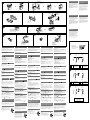
Retrait du tour de protection et du
support
Avant d’installer l’appareil, retirez le tour de protection et le
support de l’appareil.
1 Retirez le tour de protection .
Saisissez les deux bords du tour de protection , puis tirez pour
l'extraire.
2 Retirez le support .
Insérez les deux clés de déblocage simultanément entre
l’appareil et le support jusqu’au déclic indiquant qu’elles sont
en place.
Tirez le support vers le bas, puis tirez l’appareil vers le haut
pour les séparer.
Exemple de montage
Installation dans le tableau de bord
Remarques
Pliez ces griffes vers l’extérieur pour assurer une prise correcte si nécessaire (-2).
Assurez-vous que les 4 loquets du tour de protection sont correctement insérés dans les
fentes de l’appareil (-3).
Retrait et fixation de la façade
Avant d’installer l’appareil, retirez la façade.
-A Pour la retirer
Avant de détacher la façade, n’oubliez pas d’appuyer sur la touche
et de la maintenir enfoncée. Appuyez sur la touche de
déverrouillage de la façade et détachez-la en la tirant vers vous.
-B Pour la fixer
Fixez la partie de la façade sur la partie de l’appareil, comme indiqué
sur l’illustration, puis appuyez sur le côté gauche jusqu’au déclic.
Installation du microphone
Pour capturer la voix pendant un appel en mains libres, vous devez installer
le microphone (fourni).
Avertissements
Conservez le microphone à l’abri de la chaleur et de l’humidité
extrêmement élevées.
Il est extrêmement dangereux que le cordon s’enroule autour de la
colonne de direction ou du changement de vitesse. Veillez à ce que le
cordon et les autres pièces n’entravent pas la conduite.
Si votre véhicule est équipé d’airbags ou d’autres dispositifs d’absorption
des chocs, contactez le revendeur de l’appareil ou votre concessionnaire
avant de procéder à l’installation.
-A Installation sur le pare-soleil
1 Fixez le microphone
a
au clip
b
.
2 Fixez le clip
b
au pare-soleil.
3 Fixez des clips (non fournis), puis réglez la longueur et la
position du cordon afin qu’il n’entrave pas la conduite.
-B Installation sur le tableau de bord
1 Fixez le microphone
a
au clip
b
, puis placez le cordon dans la
rainure du clip
b
.
2 Fixez le clip
b
au tableau de bord avec de l’adhésif double face
c
.
3 Fixez un clip (non fourni), puis réglez la longueur et la position
du cordon afin qu’il n’entrave pas la conduite.
Remarques
Avant de fixer l’adhésif double face
c
, nettoyez la surface du tableau de bord avec un chiffon
sec.
Réglez l’angle du microphone sur la position correcte.
Le microphone
a
peut être installé sans utiliser le clip
b
.
Dans ce cas, fixez le microphone directement au tableau de bord avec de l’adhésif double
face
c
. Conservez le clip de réserve
b
en vue d’une utilisation ultérieure.
Avertissement au cas où le contact de
votre voiture ne dispose pas d’une
position ACC
Veillez à régler la fonction de mise hors tension automatique. Pour obtenir
davantage d’informations, reportez-vous au mode d’emploi fourni.
L’appareil s’éteint complètement et automatiquement après le laps de temps
choisi une fois l’appareil mis hors tension afin d’éviter que la batterie ne se
décharge.
Si vous ne réglez pas la fonction de mise hors tension automatique, appuyez
sur la touche et maintenez-la enfoncée jusqu’à ce que
l’affichage disparaisse à chaque fois que vous coupez le contact.
Remplacement du fusible
Lorsque vous remplacez le fusible, veillez à utiliser un
fusible dont l’intensité, en ampères, correspond à la
valeur indiquée sur le fusible usagé.
Si le fusible saute, vérifiez le branchement de
l’alimentation et remplacez-le.
Si le nouveau fusible saute également, il est possible
que l’appareil soit défectueux. Dans ce cas, consultez
votre revendeur Sony le plus proche.
Fusible (10 A)
Sicherheitshinweise
Wählen Sie den Einbauort sorgfältig so aus, dass das Gerät beim Fahren
nicht hinderlich ist.
Bauen Sie das Gerät so ein, dass es keinen hohen Temperaturen (keinem
direkten Sonnenlicht, keiner Warmluft von der Heizung), keinem Staub,
keinem Schmutz und keinen starken Vibrationen ausgesetzt ist.
Für eine sichere Befestigung verwenden Sie stets die mitgelieferten
Montageteile.
Hinweis zum Montagewinkel
Das Gerät sollte in einem Winkel von weniger als 45° montiert werden.
Abnehmen der Schutzumrandung und
der Halterung
Nehmen Sie vor dem Installieren des Geräts die Schutzumrandung
und die Halterung vom Gerät ab.
1 Entfernen Sie die Schutzumrandung .
Fassen Sie die Schutzumrandung mit den Fingern an den
Seitenkanten und ziehen Sie sie heraus.
2 Entfernen Sie die Halterung .
Führen Sie beide Löseschlüssel zwischen dem Gerät und der
Halterung ein, bis sie mit einem Klicken einrasten.
Ziehen Sie die Halterung nach unten und das Gerät nach
oben, um die beiden zu trennen.
Montagebeispiel
Installation im Armaturenbrett
Hinweise
Falls erforderlich, biegen Sie diese Klammern für einen sicheren Halt nach außen (-2).
Achten Sie darauf, die 4 Verriegelungen an der Schutzumrandung korrekt in die
Aussparungen am Gerät einzusetzen (-3).
Abnehmen und Anbringen der
Frontplatte
Nehmen Sie die Frontplatte vor dem Einbau des Geräts ab.
-A Abnehmen
Halten Sie vor dem Abnehmen der Frontplatte unbedingt
gedrückt. Drücken Sie die Taste zum Lösen der Frontplatte und ziehen Sie
die Frontplatte auf sich zu und heraus.
-B Anbringen
Setzen Sie Teil der Frontplatte wie in der Abbildung dargestellt an Teil
des Geräts an und drücken Sie die linke Seite der Frontplatte an, bis sie
mit einem Klicken einrastet.
Installieren des Mikrofons
Damit bei Freisprechanrufen Ihre Stimme übertragen werden kann,
müssen Sie das Mikrofon (mitgeliefert) installieren.
Sicherheitshinweise
Schützen Sie das Mikrofon vor extrem hohen Temperaturen und
Feuchtigkeit.
Es ist sehr gefährlich, wenn sich das Kabel um die Lenksäule oder den
Schalthebel wickelt. Achten Sie unbedingt darauf, dass das Kabel und
andere Teile beim Fahren nicht hinderlich sind.
Wenn Ihr Auto mit Airbags oder anderen Aufprallschutzsystemen
ausgestattet ist, wenden Sie sich vor der Installation an den Händler, bei
dem Sie dieses Gerät erworben haben, oder an den Autohändler.
-A Befestigung an der Sonnenblende
1 Befestigen Sie das Mikrofon
a
am Clip
b
.
2 Bringen Sie den Clip
b
an der Sonnenblende an.
3 Bringen Sie Clips (nicht mitgeliefert) an und wählen Sie die
Länge und Verlegung des Kabels so, dass es beim Fahren nicht
hinderlich ist.
-B Befestigung am Armaturenbrett
1 Befestigen Sie das Mikrofon
a
am Clip
b
und führen Sie das
Kabel entlang der Kerbe des Clips
b
.
2 Bringen Sie den Clip
b
mit dem doppelseitigen Klebeband
c
am Armaturenbrett an.
3 Bringen Sie einen Clip (nicht mitgeliefert) an und wählen Sie die
Länge und Verlegung des Kabels so, dass es beim Fahren nicht
hinderlich ist.
Hinweise
Reinigen Sie die Oberfläche des Armaturenbretts mit einem trockenen Tuch, bevor Sie das
doppelseitige Klebeband
c
anbringen.
Stellen Sie den Mikrofonwinkel nach Bedarf ein.
Das Mikrofon
a
kann auch ohne Clip
b
befestigt werden.
Bringen Sie das Mikrofon in diesem Fall mit dem doppelseitigen Klebeband
c
direkt am
Armaturenbrett an. Bewahren Sie den nicht verwendeten Clip
b
zum späteren Gebrauch auf.
Warnhinweis, wenn die Zündung Ihres
Fahrzeugs nicht über eine
Zubehörposition (ACC oder I) verfügt
Aktivieren Sie unbedingt die Abschaltautomatik. Näheres dazu finden Sie
in der mitgelieferten Bedienungsanleitung.
Nach dem Ausschalten wird das Gerät dann nach der voreingestellten Zeit
automatisch vollständig abgeschaltet, so dass der Autobatterie kein Strom
mehr entzogen wird.
Wenn Sie die Abschaltautomatik nicht aktivieren, müssen Sie jedes Mal,
wenn Sie die Zündung ausschalten, die Taste gedrückt
halten, bis die Anzeige ausgeblendet wird.
Austauschen der Sicherung
Wenn Sie eine Sicherung austauschen, achten Sie
darauf, eine Ersatzsicherung mit dem gleichen
Ampere-Wert wie die Originalsicherung zu
verwenden. Dieser ist auf der Originalsicherung
angegeben.
Wenn die Sicherung durchbrennt, überprüfen Sie den
Stromanschluss und tauschen die Sicherung aus.
Brennt die neue Sicherung ebenfalls durch, kann eine
interne Fehlfunktion vorliegen. Wenden Sie sich in
einem solchen Fall an Ihren Sony-Händler.
Sicherung (10 A)
Precauzioni
Scegliere con attenzione la posizione per l’installazione in modo che
l’apparecchio non interferisca con le operazioni di guida del conducente.
Evitare di installare l’apparecchio dove sia soggetto ad alte temperature,
come alla luce solare diretta o al getto di aria calda dell’impianto di
riscaldamento, o dove possa essere soggetto a polvere, sporco e vibrazioni
eccessive.
Usare solo il materiale di montaggio in dotazione per un’installazione
stabile e sicura.
Regolazione dell’angolo di montaggio
Regolare l’angolo di montaggio in modo che sia inferiore a 45°.
Rimozione della staffa e della cornice
protettiva
Prima di installare l’apparecchio, rimuovere la cornice protettiva
e la staffa dall’apparecchio.
1 Rimuovere la cornice protettiva .
Afferrare la cornice di protezione dai bordi laterali, quindi
estrarla.
2 Rimuovere la staffa .
Inserire contemporaneamente entrambe le chiavette di rilascio
tra l’apparecchio e la staffa fino a che non scattano in
posizione.
Estrarre la staffa quindi sollevare l’apparecchio per
rimuoverlo.
Esempio di montaggio
Installazione nel cruscotto
Note
Piegare verso l’esterno questi morsetti per un’installazione più sicura, se necessario (-2).
Assicurarsi che i 4 fermi sulla cornice protettiva siano correttamente inseriti negli
alloggiamenti dell’apparecchio (-3).
Come rimuovere e reinserire il pannello
anteriore
Prima di installare l’apparecchio rimuovere il pannello anteriore.
-A Per rimuoverlo
Prima di staccare il pannello anteriore, assicurarsi di tenere premuto
. Premere il tasto rilascio pannello anteriore, quindi tirare
il pannello verso di sé.
-B Per reinserirlo
Applicare la parte del pannello anteriore alla parte dell’apparecchio
come mostrato nell’illustrazione e premere il lato sinistro fino a sentire uno
scatto.
Installazione del microfono
Per catturare la voce durante le chiamate vivavoce, è necessario installare il
microfono (in dotazione).
Attenzione
Non sottoporre il microfono a temperature e umidità eccessivamente
elevate.
Se il cavo rimane avvolto al piantone dello sterzo o alla leva del cambio,
possono verificarsi situazioni di estremo pericolo. Accertarsi quindi di
posizionare il cavo e altri componenti in modo che non ostruiscano la guida.
Se nell’auto sono presenti air-bag o altri dispositivi di assorbimento degli
urti, prima dell’installazione contattare il negozio in cui è stato acquistato
l’apparecchio o l’autoconcessionario.
-A Installazione sull’aletta parasole
1 Installare il microfono
a
sul fermaglio
b
.
2 Installare il fermaglio
b
sull’aletta parasole.
3 Installare i fermagli (non in dotazione) e regolare la lunghezza e
la posizione del cavo in modo che non ostacoli la guida.
-B Installazione sul cruscotto
1 Installare il microfono
a
sul fermaglio
b
, quindi inserire il cavo
nella scanalatura del fermaglio stesso
b
.
2 Applicare il fermaglio
b
al cruscotto utilizzando il nastro
biadesivo
c
.
3 Installare un fermaglio (non in dotazione) e regolare la lunghezza
e la posizione del cavo in modo che non ostacoli la guida.
Note
Prima di applicare il nastro biadesivo
c
, pulire la superficie del cruscotto con un panno
asciutto.
Regolare l’angolazione del microfono sulla posizione corretta.
È possibile anche installare il microfono
a
senza utilizzare il fermaglio
b
.
In questo caso, applicare direttamente il microfono al cruscotto utilizzando il nastro
biadesivo
c
. Conservare il fermaglio inutilizzato
b
per usi futuri.
Avvertenza relativa all’installazione su
un’auto sprovvista della posizione ACC
(accessoria) sul blocchetto di accensione
Accertarsi di impostare la funzione di spegnimento automatico. Per
ulteriori informazioni, fare riferimento alle istruzioni per l’uso in dotazione.
L’apparecchio si spegne completamente e automaticamente all’ora impostata
dopo che è stato disattivato, onde evitare che la batteria si scarichi.
Se la funzione di spegnimento automatico non è stata impostata, ogni volta
che il motore viene spento tenere premuto finché il
display non viene disattivato.
Sostituzione del fusibile
Per la sostituzione del fusibile, assicurarsi di utilizzare
un fusibile dello stesso amperaggio di quello indicato
sull’originale.
Se il fusibile si brucia, controllare i collegamenti
dell’alimentazione e sostituire il fusibile.
Se dopo la sostituzione il fusibile si brucia di nuovo, è
possibile che si tratti di un problema interno. In tal
caso, rivolgersi al più vicino rivenditore Sony.
Fusibile (10 A)
Voorzorgsmaatregelen
Kies de installatieplaats zorgvuldig zodat het apparaat de bestuurder niet
hindert tijdens het rijden.
Installeer het apparaat niet op plaatsen waar het blootgesteld wordt aan
hoge temperaturen, bv. in direct zonlicht of bij de warme luchtstroom van
de autoverwarming, aan sterke trillingen, of waar het in contact komt met
veel stof of vuil.
Gebruik voor het veilig en stevig monteren van het apparaat uitsluitend
de bijgeleverde montage-onderdelen.
Maximale montagehoek
Installeer het apparaat nooit in een hoek van meer dan 45° met het
horizontale vlak.
De beschermende rand en de beugel
verwijderen
Voordat u het apparaat gaat installeren, moet u de beschermende
rand en de beugel verwijderen van het apparaat.
1 Verwijder de beschermende rand .
Druk beide zijden van de beschermende rand in en trek de rand
naar u toe.
2 Verwijder de beugel .
Plaats de ontgrendelingssleutels tussen het apparaat en de
beugel tot deze vastklikken.
Trek de beugel omlaag en trek het apparaat omhoog om
deze van elkaar te scheiden.
Montagevoorbeeld
Montage in het dashboard
Opmerkingen
Indien nodig kunt u deze klemhaken ombuigen voor een stevigere bevestiging (-2).
De 4 grepen op de beschermende rand moeten goed in de sleuven van het apparaat zijn
geplaatst (-3).
Het voorpaneel verwijderen en
bevestigen
Verwijder, alvorens met het installeren te beginnen, het afneembare
voorpaneel.
-A Verwijderen
Voordat u het voorpaneel verwijdert, moet u ingedrukt
houden. Druk op de toets om het voorpaneel los te maken en trek het
voorpaneel naar u toe.
-B Bevestigen
Breng deel van het voorpaneel aan op deel van het apparaat zoals
afgebeeld en druk op de linkerzijde tot deze vastklikt.
De microfoon installeren
Om uw stem te kunnen registreren tijdens het handsfree bellen, moet u de
microfoon (bijgeleverd) installeren.
Opgelet
Stel de microfoon niet bloot aan extreem hoge temperaturen of aan een
hoge vochtigheidsgraad.
Het is uiterst gevaarlijk als de kabel rond de stuurkolom of de
versnellingspook verstrikt raakt. Zorg ervoor dat de kabel en andere
onderdelen u niet kunnen hinderen tijdens het rijden.
Als uw auto uitgerust is met airbags of andere schokdempende
apparatuur, contacteert u de winkel waar u dit apparaat hebt gekocht of
uw autodealer voor u het apparaat installeert.
-A Bevestigen aan de zonneklep
1 Bevestig de microfoon
a
aan de klem
b
.
2 Bevestig de klem
b
aan de zonneklep.
3 Gebruik klemmen (niet bijgeleverd) en pas de lengte en positie
van de kabel aan zodat deze u niet hindert tijdens het rijden.
-B Bevestigen op het dashboard
1 Bevestig de microfoon
a
aan de klem
b
en plaats de kabel in de
gleuf in de klem
b
.
2 Bevestig de klem
b
op het dashboard met behulp van de
dubbelzijdige kleefband
c
.
3 Gebruik een klem (niet bijgeleverd) en pas de lengte en positie
van de kabel aan zodat deze u niet hindert tijdens het rijden.
Opmerkingen
Voor u de dubbelzijdige kleefband vastmaakt
c
, reinigt u het oppervlak van het dashboard
met een droge doek.
Breng de microfoon in de juiste hoek.
De microfoon
a
kan ook geïnstalleerd worden zonder de klem
b
te gebruiken.
Bevestig in dit geval de microfoon rechtstreeks op het dashboard met behulp van de
dubbelzijdige kleefband
c
. Bewaar de ongebruikte klem
b
voor toekomstig gebruik.
Waarschuwing als het contactslot van
de auto geen ACC-positie heeft
Zorg ervoor dat u de functie voor automatisch uitschakelen instelt.
Raadpleeg de bijgeleverde gebruiksaanwijzing voor meer informatie.
Het apparaat wordt na de ingestelde tijd automatisch volledig uitgeschakeld
nadat het apparaat is uitgeschakeld. Zo wordt voorkomen dat de accu
leegloopt.
Als u de functie voor automatisch uitschakelen niet instelt, moet u
ingedrukt houden tot het display verdwijnt telkens
wanneer u het contact uitschakelt.
Zekering vervangen
Vervang een zekering altijd door een exemplaar van
een zelfde ampèrage als op de oorspronkelijke
zekering wordt vermeld.
Als de zekering doorbrandt, moet u de
voedingsaansluiting controleren en de zekering
vervangen.
Brandt de zekering vervolgens nogmaals door, dan
kan er sprake zijn van een defect in het apparaat.
Raadpleeg in dat geval de Sony-dealer bij u in de
buurt.
Zekering (10 A)
the car without ACC position
Fahrzeug ohne Zubehörposition (ACC oder I)
Véhicule sans position ACC
Auto priva della posizione ACC
Auto zonder ACC-positie
4
Yellow
Gelb
Jaune
Giallo
Geel
continuous power supply
permanente Stromversorgung
alimentation continue
alimentazione continua
continue voeding
7
Red
Rot
Rouge
Rosso
Rood
switched power supply
geschaltete Stromversorgung
alimentation commutée
alimentazione commutata
geschakelde voeding
4
Yellow
Gelb
Jaune
Giallo
Geel
switched power supply
geschaltete Stromversorgung
alimentation commutée
alimentazione commutata
geschakelde voeding
7
Red
Rot
Rouge
Rosso
Rood
continuous power supply
permanente Stromversorgung
alimentation continue
alimentazione continua
continue voeding
Precautions
Choose the installation location carefully so that the unit will not
interfere with normal driving operations.
Avoid installing the unit in areas subject to dust, dirt, excessive vibration,
or high temperature, such as in direct sunlight or near heater ducts.
Use only the supplied mounting hardware for a safe and secure
installation.
Mounting angle adjustment
Adjust the mounting angle to less than 45°.
Removing the protection collar and the
bracket
Before installing the unit, remove the protection collar and the
bracket from the unit.
1 Remove the protection collar .
Pinch both edges of the protection collar , then pull it out.
2 Remove the bracket .
Insert both release keys together between the unit and the
bracket until they click.
Pull down the bracket , then pull up the unit to separate.
Mounting example
Installation in the dashboard
Notes
Bend these claws outward for a tight fit, if necessary (-2).
Make sure that the 4 catches on the protection collar are properly engaged in the slots of
the unit (-3).
How to detach and attach the front
panel
Before installing the unit, detach the front panel.
-A To detach
Before detaching the front panel, be sure to press and hold
. Press the front panel release button, and pull it off
towards you.
-B To attach
Engage part of the front panel with part of the unit, as illustrated, and
push the left side into position until it clicks.
Installing the microphone
To capture your voice during handsfree calling, you need to install the
microphone (supplied).
Cautions
Keep the microphone away from extremely high temperatures and
humidity.
It is extremely dangerous if the cord becomes wound around the steering
column or gearstick. Be sure to keep it and other parts from obstructing
your driving.
If airbags or any other shock-absorbing equipment is in your car, contact
the store where you purchased this unit, or the car dealer, before
installation.
-A Installing on the sun visor
1 Install the microphone
a
on the clip
b
.
2 Install the clip
b
on the sun visor.
3 Install clips (not supplied) and adjust the length and position of
the cord so that it does not obstruct your driving.
-B Installing on the dashboard
1 Install the microphone
a
on the clip
b
, then place the cord
along the groove of the clip
b
.
2 Attach the clip
b
to the dashboard with the double-sided tape
c
.
3 Install a clip (not supplied) and adjust the length and position of
the cord so that it does not obstruct your driving.
Notes
Before attaching the double-sided tape
c
, clean the surface of the dashboard with a dry
cloth.
Adjust the microphone angle to the proper position.
The microphone
a
can be installed without using the clip
b
.
In this case, directly attach the microphone to the dashboard with the double-sided tape
c
.
Keep the unused clip
b
for future use.
Warning if your car’s ignition has no ACC
position
Be sure to set the Auto Off function. For details, see the supplied Operating
Instructions.
The unit will shut off completely and automatically in the set time after the
unit is turned off, which prevents battery drain.
If you do not set the Auto Off function, press and hold
until the display disappears each time you turn the ignition off.
Fuse replacement
When replacing the fuse, be sure to use one matching
the amperage rating stated on the original fuse.
If the fuse blows, check the power connection and
replace the fuse.
If the fuse blows again after replacement, there may be
an internal malfunction. In such a case, consult your
nearest Sony dealer.
Fuse (10 A)
1 2
Face the hook inwards.
Der Haken muss nach innen weisen.
Tournez le crochet vers l’intérieur.
Con il gancetto rivolto verso l’interno.
Het haakje moet naar binnen wijzen.
1
2 3
Dashboard
Armaturenbrett
Tableau de bord
Cruscotto
Dashboard
Fire wall
Motorraumtrennwand
Paroi ignifuge
Parete tagliafiamma
Brandschot
Claws
Klammern
Griffes
Morsetti
Klemhaken
A
B
Front panel release button
Taste zum Lösen der Frontplatte
Touche de déverrouillage de la façade
Tasto rilascio pannello anteriore
Toets om het voorpaneel los te maken
A
21 2
B
1
b
a
b
a
b
a
Clips (not supplied)
Clips (nicht mitgeliefert)
Clips (non fournis)
Fermagli (non in dotazione)
Klemmen (niet bijgeleverd)
c
b
a
Clip (not supplied)
Clip (nicht mitgeliefert)
Clip (non fourni)
Fermaglio (non in dotazione)
Klem (niet bijgeleverd)
-
 1
1
-
 2
2


Sony MEX-BT4000U Manuale del proprietario
- Categoria
- Microfoni
- Tipo
- Manuale del proprietario
in altre lingue
- English: Sony MEX-BT4000U Owner's manual
- français: Sony MEX-BT4000U Le manuel du propriétaire
- Deutsch: Sony MEX-BT4000U Bedienungsanleitung
- Nederlands: Sony MEX-BT4000U de handleiding
Documenti correlati
-
Sony MEX-DV1000 Guida d'installazione
-
Sony MEX-N4000BT Manuale del proprietario
-
Sony MEX-BT2900 Guida d'installazione
-
Sony MEX-BT3100U Guida d'installazione
-
Sony DSX-A50BT Guida d'installazione
-
Sony CDX-GT550UI Guida d'installazione
-
Sony CDX-GT260MP Manuale del proprietario
-
Sony MEX-BT5700U Manuale del proprietario