MSI MAG B550 Tomahawk Max Wifi Motherboard Guida utente
- Categoria
- Schede madri
- Tipo
- Guida utente

I
MAG B550 TOMAHAWK MAX WIFI
Motherboard
User Guide
Benutzerhandbuch
Manuel d’utilisation
Руководство пользователя
取扱説明書
사용 명서
使用手冊
使用手册


III
Quick Start
Quick Start
Thank you for purchasing the MSI® motherboard. This Quick Start section provides
demonstration diagrams about how to install your computer. Some of the installations
also provide video demonstrations. Please link to the URL to watch it with the web
browser on your phone or tablet. You may have even link to the URL by scanning the
QR code.
Kurzanleitung
Danke, dass Sie das MSI® Motherboard gewählt haben. Dieser Abschnitt der
Kurzanleitung bietet eine Demo zur Installation Ihres Computers. Manche
Installationen bieten auch die Videodemonstrationen. Klicken Sie auf die URL, um
diese Videoanleitung mit Ihrem Browser auf Ihrem Handy oder Table anzusehen. Oder
scannen Sie auch den QR Code mit Ihrem Handy, um die URL zu öffnen.
Présentation rapide
Merci d’avoir choisi la carte mère MSI®. Ce manuel fournit une rapide présentation
avec des illustrations explicatives qui vous aideront à assembler votre ordinateur.
Des tutoriels vidéo sont disponibles pour certaines étapes. Cliquez sur le lien fourni
pour regarder la vidéo sur votre téléphone ou votre tablette. Vous pouvez également
accéder au lien en scannant le QR code qui lui est associé.
Благодарим вас за покупку материнской платы MSI®. В этом разделе представлена
информация, которая поможет вам при сборке комьютера. Для некоторых этапов
сборки имеются видеоинструкции. Для просмотра видео, необходимо открыть
соответствующую ссылку в веб-браузере на вашем телефоне или планшете. Вы
также можете выполнить переход по ссылке, путем сканирования QR-кода.
この度は MSI® マザーボードをお買い上げいただき、誠にありがとうございます。このクイッ
クスタートにはPCの組み立て方法のデモンストレーション図を掲載しています。いくつかの
組み立て手順に付きましては、実演ビデオを提供しています。スマートフォンやタブレット端
末のウェブブラウザで本書に記載されたURLにアクセスしてご覧ください。QRコードをスキ
ャンすることでもURLのリンク先をご参照頂けます。
MSI® 메인보드를 선택해주셔서 감사합니다. 이 부분에서는 컴퓨터를 설치하는 방법에 대한
데모 다이어그램과 일부 데모 동영상을 제공하고 있습니다. 휴대전화 또는 태블릿의 웹
브라우저를 통하여 URL에 링크한 후 설치 동영상을 감상하시기 바랍니다. 또는 QR 코드를
스캔하여 URL에 링크할 수도 있습니다.
感謝您購買 MSI® 主機板。本快速指引章節提供您安裝電腦的示範圖解,亦提供部分組件
的安裝示範影片;請您以智慧型手機或平板的瀏覽器連上 URL 網址進行觀看。您也可以
掃描 QR code 的方式快速連接至網址。
感谢您购买 MSI® 主板。本快速入门部分提供了有关如何安装计算机演示图。某些设施还
提供了视频演示。请使用您的手机或平板电脑上的网页浏览器链接至网址观看。您也可以
通过扫描QR码链接到URL。

IV Quick Start
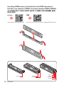
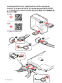
Installing a Processor/ Installation des Prozessors/ Installer un
1
2
3
6
4
5
7
8
9
Youtube
http://v.youku.com/v_show/id_
XMTg2MjMwOTE2NA==.html
https://youtu.be/Xv89nhFk1vc

V
Quick Start
1
2
3
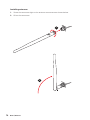
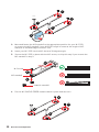
If you are installing the screw-type CPU heatsink, please follow the figure below
to remove the retention module first and then install the heatsink.
Wenn Sie einen CPU-Kühler mit Schraubenbefestigung einsetzen, folgen Sie bitte
den Anweisungen unten um das Retention-Modul zu entfernen und den Kühler zu
installieren.
Si vous voulez installer un ventirad pour processeur à vis, veuillez suivre les
instructions ci-dessous pour d’abord retirer le module de rétention puis installer le
ventirad.
В случае установки процессорного кулера с системой крепления на винтах,
следуйте указаниям на рисунке ниже для снятия пластикового модуля крепления.
Затем установите кулер.
スクリュータイプのCPUクーラーを取り付ける場合は、下記の図のように、まずリテンション
モジュールを外してからCPUクーラーを取り付けて下さい。
나사타입의 CPU 히트싱크를 장착 할 경우, 아래 그림과 같이 쿨러 지지대를 제거 후
히트싱크를 장착 하십시오.
如果要安裝螺絲式的CPU散熱器,請遵照下圖步驟先移除固定模組,再安裝散熱器。
如果要安装螺丝式CPU散热器,请按照如下图步骤先移除固定模块,然后再安装散热器。

VI Quick Start
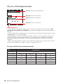
Installing DDR5 memory/ Installation des DDR5-Speichers/
http://youtu.be/T03aDrJPyQs
DIMMA2 DIMMA2
DIMMB2
DIMMA1
DIMMA2
DIMMB1
DIMMB2
Youtube
http://v.youku.com/v_show/id_XNzUyMTI5ODI4.html

VII
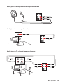
Quick Start
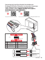
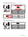
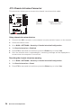
HDD LED
RESET SW
JFP1
HDD LED HDD LED -
HDD LED +
POWER LED -
POWER LED +
POWER LED
1
2 10
9
+
+
+---
-
+
Power LED
HDD LED Reset Switch
Reserved
Power Switch
JFP1
1 HDD LED + 2 Power LED +
3HDD LED - 4Power LED -
5 Reset Switch 6 Power Switch
7 Reset Switch 8 Power Switch
9 Reserved 10 No Pin
RESET SW
POWER SW
POWER LED+
POWER LED-
HDD LED
http://youtu.be/DPELIdVNZUI
Youtube
http://v.youku.com/v_show/id_XNjcyMTczMzM2.html

VIII Quick Start
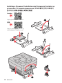
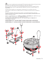
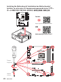
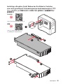
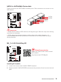
Installing the Motherboard/ Installation des Motherboards/
https://youtu.be/wWI6Qt51Wnc
Youtube
https://v.youku.com/v_show/id_
XNDUwMDUyNTkwOA==.html
1
3
Torque:
3 kgf·cm*
*3 kgf·cm
= 0.3 N·m
= 2.6 lbf·in

IX
Quick Start
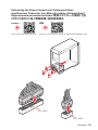
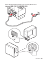
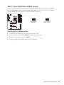
ATX_PWR1
CPU_PWR1
http://youtu.be/gkDYyR_83I4 http://v.youku.com/v_show/id_XNDkzODU0MDQw.html
Youtube


XII Quick Start
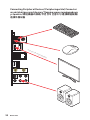
Processor with integrated graphics

XIII
Quick Start
4
3
12

1
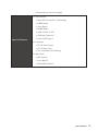
Safety Information ................................................................................................. 3
Specifications ......................................................................................................... 4
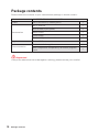
Package contents ................................................................................................ 10
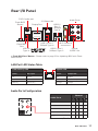
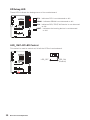
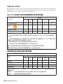
Rear I/O Panel ..................................................................................................... 11
LAN Port LED Status Table .................................................................................. 11
Audio Ports Configuration .................................................................................... 11
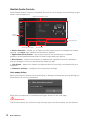
Realtek Audio Console ......................................................................................... 12
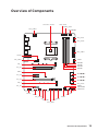
.................................................................................... 15
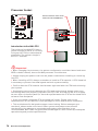
Processor Socket ................................................................................................. 16
DIMM Slots ............................................................................................................ 17
PCI_E1~4: PCIe Expansion Slots .......................................................................... 18
SATA1~6: SATA 6Gb/s Connectors ....................................................................... 19
M2_1~2: M.2 Slots (Key M) ................................................................................... 19
JFP1, JFP2: Front Panel Connectors ................................................................... 21
JAUD1: Front Audio Connector ............................................................................ 21
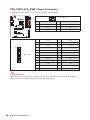
CPU_PWR1, ATX_PWR1: Power Connectors ....................................................... 22
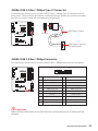
JUSB4: USB 3.2 Gen 1 5Gbps Type-C Connector ................................................. 23
JUSB3: USB 3.2 Gen 1 5Gbps Connector ............................................................. 23
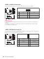
JUSB1~2: USB 2.0 Connectors ............................................................................. 24
JTPM1: TPM Module Connector ........................................................................... 24
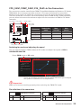
CPU_FAN1, PUMP_FAN1, SYS_FAN1~6: Fan Connectors .................................. 25
JCI1: Chassis Intrusion Connector ....................................................................... 26
JBAT1: Clear CMOS (Reset BIOS) Jumper ........................................................... 27
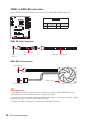
JRGB1~2: RGB LED connectors ........................................................................... 28
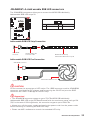
JRAINBOW1~2: Addressable RGB LED connectors ............................................ 29
EZ Debug LED ....................................................................................................... 30
LED_SW1: EZ LED Control ................................................................................... 30
......................................................................... 31
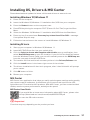
Installing Windows® 10 ......................................................................................... 31
Installing Drivers .................................................................................................. 31
Installing Utilities ................................................................................................. 31
............................................................................................................. 32
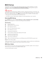
BIOS Setup ............................................................................................................ 33
Entering BIOS Setup ............................................................................................. 33
Resetting BIOS ...................................................................................................... 34
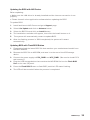
Updating BIOS ....................................................................................................... 34
EZ Mode ................................................................................................................ 36
English

2
Advanced Mode .................................................................................................... 39
OC Menu................................................................................................................ 40

3
Safety Information
Safety Information
The components included in this package are prone to damage from electrostatic
discharge (ESD). Please adhere to the following instructions to ensure successful
computer assembly.
Ensure that all components are securely connected. Loose connections may cause
the computer to not recognize a component or fail to start.
Hold the motherboard by the edges to avoid touching sensitive components.
It is recommended to wear an electrostatic discharge (ESD) wrist strap when
handling the motherboard to prevent electrostatic damage. If an ESD wrist strap is
not available, discharge yourself of static electricity by touching another metal object
before handling the motherboard.
Store the motherboard in an electrostatic shielding container or on an anti-static
pad whenever the motherboard is not installed.
Before turning on the computer, ensure that there are no loose screws or metal
components on the motherboard or anywhere within the computer case.
Do not boot the computer before installation is completed. This could cause
permanent damage to the components as well as injury to the user.
If you need help during any installation step, please consult a certified computer
technician.
Always turn off the power supply and unplug the power cord from the power outlet
before installing or removing any computer component.
Keep this user guide for future reference.
Keep this motherboard away from humidity.
Make sure that your electrical outlet provides the same voltage as is indicated on
the PSU, before connecting the PSU to the electrical outlet.
Place the power cord such a way that people can not step on it. Do not place
anything over the power cord.
All cautions and warnings on the motherboard should be noted.
If any of the following situations arises, get the motherboard checked by service
personnel:
Liquid has penetrated into the computer.
The motherboard has been exposed to moisture.
The motherboard does not work well or you can not get it work according to user
guide.
The motherboard has been dropped and damaged.
The motherboard has obvious sign of breakage.
Do not leave this motherboard in an environment above 60°C (140°F), it may damage
the motherboard.

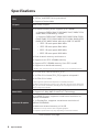
4Specifications
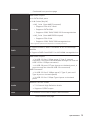
Specifications
Supports AMD Ryzen™ 5000 Series, 5000 G-Series, 4000
G-Series, and 3000 Series processors
Supports Socket AM4
AMD B550 Chipset
Memory
4x DDR4 memory slots, support up to 128GB*
Supports DDR4 1866/ 2133/ 2400/ 2667/ 2800/ 2933/
3000/ 3066/ 3200 MHz by JEDEC
Supports DDR4 2667/ 2800 /2933 /3000 /3066 /3200
/3466 /3600/ 3733 /3866 /4000 /4133 /4266 /4400 /4533
/4600 /4733/ 4800/ 4866+ MHz by A-XMP OC MODE
1DPC 1R max speed 4866 MHz
1DPC 2R max speed 3866 MHz
2DPC 1R max speed 4000 MHz
2DPC 2R max speed 3600 MHz
Dual channel memory architecture
Supports non-ECC UDIMM memory
Supports ECC UDIMM memory (non-ECC mode)
Supports un-buffered memory
* Please refer www.msi.com for more information on compatible memory.
Expansion Slot
1x PCIe 4.0/ 3.0 x16 slot (PCI_E1)*
1x PCIe 3.0 x16 slot (PCI_E3), supports x4 speed**
2x PCIe 3.0 x1 slots
* The supported specification depends on installed processor.
** When installing devices in M.2_2, PCI_E2 & PCI_E3 slots at the same time,
PCI_E3 slot will be unavailable, and M2_2 slot only supports PCIe x2. Please
refer to page 18 for details.
Supports 2-Way AMD CrossFire™ Technology
Onboard Graphics
1x HDMI 2.1 port, supports a maximum resolution of
4096x2160 @60Hz*
1x DisplayPort, supports a maximum resolution of
4096x2160 @60Hz*
Maximum shared memory of 16 GB
* Available for the processor with integrated graphics.
** Graphics specifications may vary depending on the CPU installed.
Continued on next page

5
Specifications
Continued from previous page
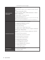
Storage
AMD B550 Chipset
6x SATA 6Gb/s ports
2x M.2 slots (Key M)
M2_1 slot (from AMD Processor)
Supports PCIe 4.0/ 3.0 x4*
Supports SATA 6Gb/s
Supports 2242/ 2260/ 2280/ 22110 storage devices
M2_2 slot (from AMD B550 chipset)
Supports PCIe 3.0x4
Supports 2242/ 2260/ 2280 storage devices
* The supported specification depends on installed processor.
RAID
Supports RAID 0, RAID 1 and RAID 10 for SATA storage
devices
Supports RAID 0 and RAID 1 for M.2 NVMe storage devices
AMD B550 Chipset
3x USB 3.2 Gen 1 5Gbps ports (1 Type-C internal
connector, and 2 ports are available through the internal
USB 3.2 Gen 1 5Gbps connector)
6x USB 2.0 ports (2 Type-A ports on the back panel, 4
ports through the internal USB 2.0 connectors)
AMD Processor
2x USB 3.2 Gen 2 10Gbps ports (1 Type-C port and 1
Type-A port on the back panel)
2x USB 3.2 Gen 1 5Gbps Type-A ports on the back
panel
Audio
Realtek® ALC897 Codec
7.1-Channel High Definition Audio
Supports S/PDIF output
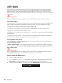
LAN 1x Realtek® RTL8125B 2.5Gbps LAN controller
Continued on next page

6Specifications
Continued from previous page
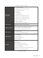
Wireless LAN &
Bluetooth®
AMD® Wi-Fi 6E*
The Wireless module is pre-installed in the M.2 (Key-E)
slot
Supports MU-MIMO TX/RX
Supports 20MHz, 40MHz, 80MHz bandwidth in 2.4GHz/
5GHz or 6GHz bands
Supports 802.11 a/ b/ g/ n/ ac/ ax
Supports Bluetooth® 5.2**
* Wi-Fi 6E 6GHz may depend on every country’s regulations and will be ready in
Windows 10 version 21H1 and Windows 11.
** Bluetooth 5.2 will be ready in Windows 10 version 21H1 and Windows 11.
1x 24-pin ATX main power connector
1x 8-pin ATX 12V power connector
6x SATA 6Gb/s connectors
2x M.2 slots (M-Key)
1x USB 3.2 Gen 1 5Gbps Type-C port
1x USB 3.2 Gen 1 5Gbps connector (supports additional 2
USB 3.2 Gen 1 5Gbps ports)
2x USB 2.0 connectors (supports additional 4 USB 2.0
ports)
1x 4-pin CPU fan connector
1x 4-pin water-pump fan connector
6x 4-pin system fan connectors
1x Front panel audio connector
2x System panel connectors
1x Chassis Intrusion connector
2x 4-pin RGB LED connectors
2x 3-pin RAINBOW LED connectors
1x TPM module connector
1x Clear CMOS jumper
LED Features 1x EZ LED Control switch
4x EZ Debug LED
Continued on next page

7
Specifications
Continued from previous page
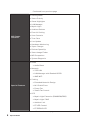
Back Panel
1x Flash BIOS Button
1x PS/2 keyboard/ mouse combo port
2x USB 2.0 Type-A ports
1x Display port
1x HDMI port
1x LAN (RJ45) port
2x USB 3.2 Gen 1 5Gbps Type-A ports
1x USB 3.2 Gen 2 10Gbps Type-A port
1x USB 3.2 Gen 2 10Gbps Type-C port
2x Wi-Fi Antenna connectors
5x OFC audio jacks
1x Optical S/PDIF Out connector
NUVOTON NCT6687-R Controller Chip
CPU/ System/ Chipset temperature detection
CPU/ System/ Pump fan speed detection
CPU/ System/ Pump fan speed control
Form Factor ATX Form Factor
12 in. x 9.6 in. (30.5 cm x 24.4 cm)
BIOS Features
1x 256 Mb flash
UEFI AMI BIOS
ACPI 6.0, SMBIOS 2.8
Multi-language
Drivers
MSI CENTER
MSI APP Player (BlueStacks)
Open Broadcaster Software (OBS)
CPU-Z MSI GAMING
Google Chrome™, Google Toolbar, Google Drive
Norton™ Internet Security Solution
Continued on next page
La pagina sta caricando ...
La pagina sta caricando ...
La pagina sta caricando ...
La pagina sta caricando ...
La pagina sta caricando ...
La pagina sta caricando ...
La pagina sta caricando ...
La pagina sta caricando ...
La pagina sta caricando ...
La pagina sta caricando ...
La pagina sta caricando ...
La pagina sta caricando ...
La pagina sta caricando ...
La pagina sta caricando ...
La pagina sta caricando ...
La pagina sta caricando ...
La pagina sta caricando ...
La pagina sta caricando ...
La pagina sta caricando ...
La pagina sta caricando ...
La pagina sta caricando ...
La pagina sta caricando ...
La pagina sta caricando ...
La pagina sta caricando ...
La pagina sta caricando ...
La pagina sta caricando ...
La pagina sta caricando ...
La pagina sta caricando ...
La pagina sta caricando ...
La pagina sta caricando ...
La pagina sta caricando ...
La pagina sta caricando ...
La pagina sta caricando ...
La pagina sta caricando ...
La pagina sta caricando ...
La pagina sta caricando ...
La pagina sta caricando ...
-
 1
1
-
 2
2
-
 3
3
-
 4
4
-
 5
5
-
 6
6
-
 7
7
-
 8
8
-
 9
9
-
 10
10
-
 11
11
-
 12
12
-
 13
13
-
 14
14
-
 15
15
-
 16
16
-
 17
17
-
 18
18
-
 19
19
-
 20
20
-
 21
21
-
 22
22
-
 23
23
-
 24
24
-
 25
25
-
 26
26
-
 27
27
-
 28
28
-
 29
29
-
 30
30
-
 31
31
-
 32
32
-
 33
33
-
 34
34
-
 35
35
-
 36
36
-
 37
37
-
 38
38
-
 39
39
-
 40
40
-
 41
41
-
 42
42
-
 43
43
-
 44
44
-
 45
45
-
 46
46
-
 47
47
-
 48
48
-
 49
49
-
 50
50
-
 51
51
-
 52
52
-
 53
53
-
 54
54
-
 55
55
-
 56
56
-
 57
57


MSI MAG B550 Tomahawk Max Wifi Motherboard Guida utente
- Categoria
- Schede madri
- Tipo
- Guida utente