Pottinger NOVACAT 8600 Istruzioni per l'uso
- Categoria
- Tosa erba
- Tipo
- Istruzioni per l'uso
Questo manuale è adatto anche per

/PERATOR@S MANUAL
GB
).3425#4)/.3 &/2 02/$5#4 $%,)6%29 0AGE
4RANSLATION OF THE ORIGINAL /PERATING -ANUAL
Ihre / Your / Votre • Masch.Nr. • Fgst.Ident.Nr.
.R
• Disc mower
99 384.GB.80J.0
NOVACAT 8600
(Type PSM 384 : + . . 01403)

ALLG./BA SEITE 2 / 0000-GB
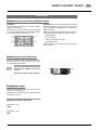
Important information concerning Product
Liability.
According to the laws governing product liability, the manufacturer and dealer are obliged to hand the
operating manual to the customer at the time of sale, and to instruct them in the recommended operating,
safety, and maintenance regulations. Confirmation is necessary to prove that the machine and operating
manual have been handed over accordingly.
For this purpose,
- document A is to be signed and sent to Pöttinger,
- document B remains with the dealer supplying the machine,
- and the customer receives document C.
In accordance with the laws of product liability, every farmer is an entrepreneur.
According to the laws of product liability, property damage is damage caused by a machine and not to
it. An excess of Euro 500 is provided for such a liabilioty.
In accordance with the laws of product liability, entrepreneurial property damages are excluded from
the liability.
Attention! Should the customer resell the machine at a later date, the operating manual must be given
to the new owner who must then be instructed in the recommended regulations referred to herein.
GB Dear Farmer
You have just made an excellent choice. Naturally we are very happy
and wish to congratulate you for having chosen Pöttinger. As your
agricultural partner, we offer you quality and efficiency combined with
reliable servicing.
In order to assess the spare-parts demand for our agricultural machines
and to take these demands into consideration when developing new
machines, we would ask you to provide us with some details.
Furthermore, we will also be able to inform you of new developments.
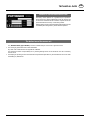
Pöttinger Newsletter
www.poettinger.at/landtechnik/index_news.htm
The latest expert information, useful links and entertainment

Dokument D
GB-0600 Dokum D Anbaugeräte
PÖTTINGER Landtechnik GmbH
Industriegelände 1
A-4710 Grieskirchen
Tel. 07248 / 600 -0
Telefax 07248 / 600-2511
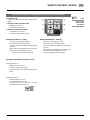
T Machine checked according to delivery note. All attached parts removed. All safety equipment, drive shaft and operating
devices at hand.
T Operation and maintenance of machine and/or implement according to operating instructions explained to the customer.
T Tyres checked re. correct pressure.
T Wheel nuts checked re. tightness.
T Drive shaft cut to correct lenght.
T *VYYLJ[WV^LY[HRLVɈZWLLKPUKPJH[LK
T Fitting to tractor carried out: to three-point linkage
T Trial run carried out and no defects found.
T Functions explained during trial run.
T Pivoting in transporting and operating position explained.
T Information given re. optional extras.
T Absolute need to read the operating manual indicated.
Please check. X
According to the product liability please check the above mentioned items.
INSTRUCTIONS FOR
PRODUCT DELIVERY
GB
In order to prove that the machine and the operating manual have been properly delivered, a confirmation is necessary.
For this purpose please do the following:
- sign the document A and send it to the company Pöttinger or via the internet to www.poettinger.at
- document B stays with the specialist factory delivering the machine.
- document C stays with the customer.

- 4 -
GB
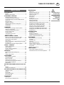
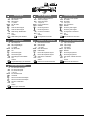
TABLE OF CONTENTS
0800_GB-Inhalt_384
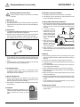
Recommendations
for work safety
All points refering
to safety in this
manual are
in di ca ted by this
sign.
Table of contents
WARNING SIGNS
CE sign ............................................................................5
Meaning of warning signs ...............................................5
ATTACHING TO TRACTOR
Attaching implement to tractor .......................................6
To make the connection to the tractor ............................7
Connecting the Sensor and valve cables from front
mower unit .......................................................................7
Fitting drive shaft ............................................................7
Hydraulic connection.......................................................8
Observe rotation direction of cutting discs .....................9
Combination 3 ...............................................................10
Combination 2 ...............................................................11
TRANSPORT
Conversion from working to transport position .............12
Raising for road transport..............................................12
Lowering into field transport position ............................12
Driving on public roads .................................................13
Transport position ..........................................................13
Unhitch device from tractor ...........................................14
Working on slopes .........................................................15
”DIRECT CONTROL” DEVICE
Meaning of the buttons on the control device ..............16
How to carry out desired hydraulic function .................16
Settings before initial operation .....................................17
Other settings ................................................................18
Setting time difference – Raising/lowering front mower
and side mower .............................................................19
Conversion from working to transport position .............20
ISOBUS - TERMINAL
Operation ISO-terminal .................................................22
Button indication ...........................................................23
Joystick - Mower Configuration ....................................25
Setting the Joystick .......................................................25
OPERATION
Important points before starting work ...........................26
Mow ...............................................................................27
Collision safety device ...................................................27
CONDITIONER
Mowing with the conditioner .........................................28
Correct belt tension .......................................................28
700 r.p.m. for rotor .........................................................28
Position of the rotor prongs ...........................................28
Dismounting and mounting the conditioner ..................29
Mowing without Conditioner .........................................32
Optional extra ................................................................32
ROLLER CONDITIONER (NOVACAT 266 F, 306
F)
Settings .........................................................................34
Cleaning and maintenance ............................................34
SET THE POSITIONS OF THE GUIDING PLATES
"Extra dry" system.........................................................35
Swathes .........................................................................35
Spread width .................................................................35
Dismount guide plate ....................................................36
Mount guide plate .........................................................36
SWATH DISCS
Swath Discs ...................................................................37
Flat cone conveyor (Optional extra) ..............................37
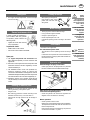
MAINTENANCE
Safety point ...................................................................38
General maintenance hints ............................................38
Cleaning of machine parts ............................................38
Parking in the ope .........................................................38
Winter storage ...............................................................38
Drive shafts ....................................................................38
Hydraulic unit ................................................................38
Oil change on cutter bar ................................................39
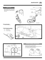
Gearing maintenance ....................................................40
Installing cutter blades .................................................40
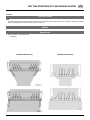
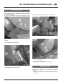
Setting the field transport position (end-of run turns) ...41
Disruptions and remedies to power failure ...................42
Checking wear on mowing blade holders .....................44
Holder for a quick change of cutter blades ...................45
Checking the mowing blade suspension ......................45
Changing the Cutter Blades (up to 2003 model) ...........45
Changing the Cutter Blades (from 2004 model) ............46
Storing the lever ............................................................46
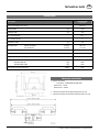
TECHNICAL DATA
Technical data ...............................................................47
Necessary connections .................................................47
The defined use of the mower unit ................................48
Position of Vehicle Identification Plate ..........................48
SUPPLEMENT
Recommendations for work safety ..............................51
Driveshaft ......................................................................52
Lubrication chart ...........................................................54
Lubricants ......................................................................57
Sensor diagnostic function ............................................59
Display for Software version..........................................59
Function check for "Direct Control" operating unit and
job calculator .................................................................59
Repairs on the cutter bar ...............................................63
TAPER BUSHES
Taper bushes installation instructions ...........................64
Combination of tractor and mounted implement ..........65

- 5 -
9700_GB-Warnbilder_361
GB
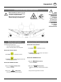
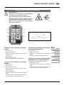
WARNING SIGNS
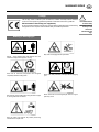
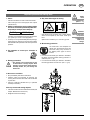
Stay clear of swinging area of implements
Close both side protective coverings before engaging
p.t.o..
Never reach into the crushing danger area as long as
parts may move.
CE sign
The CE sign, which is affixed by the manufacturer, indicates out ward ly that this machine
con forms to the engineering guideline regulations and the other relevant EU guidelines.
EU Declaration of Conformity (see supplement)
By signing the EU Declaration of Conformity, the ma nu fac tu r er declares that the machine being
brought into service complies with all relevant safety and health requirements.
Meaning of warning signs
Danger - flying objects; keep safe distance from the
machine as long as the engine is running.
Wait until all machine components have stopped
completely before touching them.
Stay clear of mower knife area as long as tractor engine
is running with PTO connected.
Shut off engine and remove key before performing
maintenance or repair work.
Recommendations
for work safety
All points referring
to satety in this
manual are
in di ca ted by this
sign.
bsb 447 410
495.167

- 6 -
0700_GB-ANBAU_3841
GB
ATTACHING TO TRACTOR
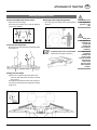
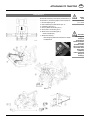
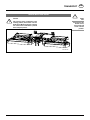
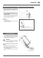
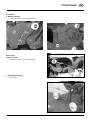
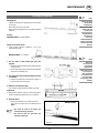
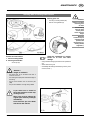
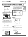
Centre-mount (M) mower unit to tractor
- Adjust lower link accordingly.
- Secure the lower hydraulic link so that the appliance
cannot swing sideways.
Frame in horizontal position
- Bring frame into horizontal position by adjusting linkage
arm spindle (15).
Setting lower link height
- Adjust tractor's hydraulics (ST) using bottom stop.
- The drive shaft (GW) should be about horizontal
when mowing.
This height allows optimal evenness when working on
uneven ground and need not be changed for swinging
cutter bar up.
TD 79/98/01
15
Attaching implement to tractor
Safety hints:
see supplement-
A1 points 7.), 8a.
- 8h.)
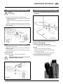
Setting upper link height using spindle
- By turning upper link spindle (16) the cutting height is
adjusted.
A hydraulic upper link is recommended.
(double-action hydraulic connection)
Safety hints
This appliance is
designed only
for use with
tractors (not
for automotive
machines).
In the case of
automotive
machines, the
driver´s visual
range is restricted
when the two
outer mower
bars are raised
in the transport
position.

- 7 -
0700_GB-ANBAU_3841
GB
ATTACHING TO TRACTOR
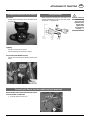
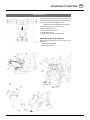
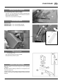
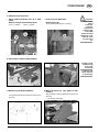
Fitting drive shaft
- Before operating for the first time, drive shaft is to be
checked and adapted if necessary. See alse chapter
"Drive Shaft" in supplement B.
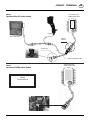
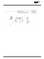
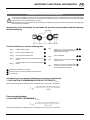
Connecting the Sensor and valve cables from front mower unit
Electrical able connections between front mower
unit and mower combination
• 3 channel cable for sensor kit (1)
To make the connection to the tractor
Operation:
- Connect the 3-channel plug to the DIN 9680 socket
on the tractor
Lighting:
- Connect 7-channel plug to tractor
- Check that lighting is functioning on wagon
For tractors with ISO Bus control
- Connect 9-channel ISO plug to ISO Bus socket on the
tractor
Important!
Before putting
the tractor into
operation check
vehicle safety
(lights, brake
unit, protective
covering, .....).

- 8 -
0700_GB-ANBAU_3841
GB
ATTACHING TO TRACTOR
7
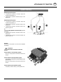
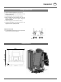
Minimal hydraulic system:
1 x single-action hydraulic connection (EW) with
unpressurized backflow (T)
1 x double-action hydraulic connection (DW), for the
starting lock
Optimal hydraulic system:
1 x single-action hydraulic connection (EW) with
unpressurized backflow (T)
1 x double-action hydraulic connection (DW) for the
starting lock
1 x double-action hydraulic connection (DW) for the
hydraulic upper link
or
Load-sensing hydraulic connection (LS) (Optional
equipment)
1 x double-action hydraulic connection (DW) for the
starting lock
1 x double-action hydraulic connection (DW)for the
hydraulic upper link
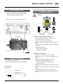
Settings
Screw (7) on the hydraulic unit must also be adjusted
accordingly.
Important!
Disconnect electrical connection
Tractors with a "Load sensing" system
- Screw (7) on the hydraulic unit must be screwed in all
the way
Tractors with a closed hydraulic system
JOHN DEERE, CASE MAXUM, CASE MAGNUM, FORD
Series 40 SLE
- Screw (7) on the hydraulic unit must be screwed in all
the way
Tractors with a open hydraulic system
- Completely unscrew screw (7) on the hydraulic unit
Hydraulic connection

- 9 -
0700_GB-ANBAU_3841
GB
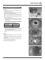
ATTACHING TO TRACTOR
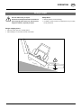
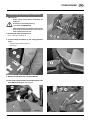
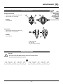
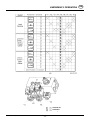
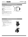
- Select appropriate rotation direction for the drive
- If the necessary p.t.o. rotation direction cannot be
selected from the tractor, rotate the mechanism (G)
180°.
Note!
Before reinstalling a gearing on the
machine:
- Swap ventilation screw and drain plug
positions.
- The correct ventilation screw position is
on top.
180°
G1
Observe rotation direction of cutting discs

- 10 -
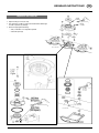
0600_GB-ANBAUTEILE_384
GB
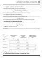
ATTACHING TO TRACTOR
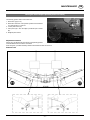
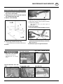
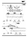
Should it be necessary to convert from Combination 2 to
Combination 3, the following steps must be carried out:
1. Remove adapter (pos. 5)
2. Detach attaching axle and install in pos. 4a
3. Install lifting gear (pos. 1)
4. Set up hydraulic connection (pos. 3)
5. Set up electric connection (pos. 2)
6. Attach mower unit to lifting gear (1)
- Attach expander (EX)
7. Attach both chains (7)
- when doing this, please note instructions in chapter
on Adjustments
Combination 3
Safety
hint:
see supplement A1/
pt. 7, 8a-8h
Take note!
The lifting gear
cannot be
progressively
raised or lowered.
When the
hydraulic control
valve is activated,
the central cutter
bar is either
completely
raised or lowered
(danger of
crushing).

- 11 -
0600_GB-ANBAUTEILE_384
GB
ATTACHING TO TRACTOR
Should it be necessary to convert from Combination 3 to
Combination 2, the following steps must be carried out:
1. Disconnect electrical connection (pos. 2)
- Attach the cable to a suitable place on the frame
2. Disconnect hydraulic connection (pos. 3)
3. Detach lifting gear (pos. 1)
4. Mount attachment axle (pos. 4)
5. Attach adapter (pos. 5)
6. Attach mower unit to tractor´s lifting gear
Attach front mower to the lifting gear
When doing this, please also note instructions in the
chapters on
- Adjustments Front-Mower
- Special Attaching Kits
Combination 2

- 12 -
0700_GB-TRANSPORT_384
GB
TRANSPORT
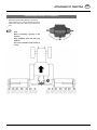
Raising for road transport
This button will only function when all cutting bars are in
the field transport position (FT)
- Turn drive off and wait for standstill
- Swing in all hoop guards on the cutting bars
Variant with "Power Control"
Press button to activate its function
Press button and all cutting bars swivel until
the end position is reached.
Variant with "ISOBUS-Terminal"
Briefly press Softkey button,
function is activated
Briefly press Softkey buton,
all mower units swivel to the end position
Lowering into field transport position
Variant with "Power Control"
Press button to activate its function
Press button and all mower units swivel to
field transport position (FT)
Variant with "ISOBUS-Terminal"
Briefly press Softkey button,
function is activated
Briefly press Softkey button,
all mower units swivel to field transport position
(FT).
- Swing out all hoop guards on the mower
• Before swivelling the cutter bar up, turn
off the drive and wait for the mower discs
to come to a complete standstill.
• Make sure that swivel area is free and that
nobody is standing in the danger area.
Conversion from working to transport position
Safety
Precaution!
Changing from
working position
to transport
position is only to
be carried out on
even, firm ground.
• Only transport
the machine in
the transport
position!

- 13 -
0700_GB-TRANSPORT_384
GB
TRANSPORT
Transport position
Driving on public roads
• Observe the official regulations of your country.
• Driving on public roads must be carried out in the
transport position only
• Protection devices must be in proper condition.
• Before travelling bring all swivelling parts into their
correct positions and secure against dangerous
changes to position.
• Check that lighting functions before travelling.
• Important information can also be found in the
supplement of this operating manual.
Hydraulic lower link
• Fix the hydraulic lower link (U) in such a way that the
machine cannot swing out sideways.
max. 4000
200
3000

- 14 -
0700_GB-TRANSPORT_384
GB
TRANSPORT
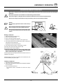
Unhitch device from tractor
Caution!
Only park the mower combination in the
working position (both mower units are
folded down). Maximum danger of tipping
over if the mower combination is parked
in the transport position.
278-09-16
Safety
note:
Only park the disc
mower on firm,
level ground and
ensure a secure
position.

0100-GB HANGFAHRT_384 - 15 -
OPERATION GB
Take care when turning on slopes!
The tractor's travelling characteristics are influenced
by the weight (G) of the mower unit. This can lead to
dangerous situations, especially on slopes.
Danger of tipping occurs
• when the mower units are in a raised position
• when travelling in a curve with the mower units raised
Safety advice
• Reduce speed in curves accordingly.
• It is better to travel in reverse on a slope than to carry out a risky
turning manoeuvre.
TD79/98/05
G
Working on slopes

GB
- 16 -
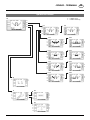
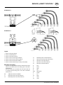
1000-GB DIRECT CONTROL_384
3. Deactivating the hydraulic function
- Press button, the integrated control light (LED) goes
off.
- The hydraulic function has been deactivated.
Safety warning: always deactivate the
selected function.
1. Press the button for desired function (11-15)
- The control light (LED) integrated in the button lights
up.
- Through pressing any other button, the hydraulic
function already selected will be deactivated, and the
new hydraulic function activated.
- Pressing button a second time deactivates the hydraulic
function once more.
2. Press one of the two arrow buttons (A1, B1)
- and the desired hydraulic function will be carried
out
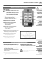
10 ON / OFF button
Important! After switching off the control
device (OFF):
- switch hydraulic control valve to the 0
position. This is absolutely essential in
the case of tractors with an open hydraulic
system - otherwise the oil will overheat.
11 Swings all mower units up and down
• Conversion from operating to transport position
and vice versa (see button 15 also)
• “load sensing” hydraulic system (LED 11)
12 Swings front mower up and down
13 Swings left mower unit up and down
Rotor r.p.m on the conditioners
1019 min-1/844 min-1
14 Swings right mower unit up and down
Rotor r.p.m on the conditioners
771 min-1/639 min-1
15 Swings all mower units up and down in the
field transport position (headland turns)
A1 Downward swing movement "Lower"
Closed hydraulic system (LED A1)
B1 Upward swing movement "Raise"
Open hydraulic system (LED B1)
Meaning of the buttons on the control device
Note!
Press the relevant
button to
preselect the
desired hydraulic
function. If one
of the two arrow
buttons (A1,
B1) are pushed
afterwards, the
desired hydraulic
function will be
carried out.
If a malfunction
occurs: see
"Establsih
power supply"
in the chapter
"ATTACHING TO
TRACTOR"
How to carry out desired hydraulic function
Control light (LED)
If one of the
control lights
(LEDs) lights up,
it means that
that particular
function has been
activated.
Example:
- The top left
integrated control
light (LED) is on
- Swing action
of left mower
unit has been
activated
”DIRECT CONTROL” DEVICE

GB”DIRECT CONTROL” DEVICE
- 17 -
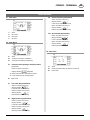
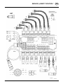
1000-GB DIRECT CONTROL_384
In general
Before initial
operation, various
selections must
be made using the
“Direct Control”
operation unit.
These selections
are particularly
important so that
the electronic
monitoring
systems are
functioning
correctly.
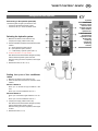
Settings before initial operation
After turning on the operation panel (ON)
The following LED will light up for about 0.5 secs:
* the LED for the selected hydraulic system
* the LED for the r.p.m. of the conditioner rotors
Selecting the hydraulic system
1. Make the connection to the switch box (E1)
Couple power supply cable to tractor (E2)
2. Press and hold down the button for the hydraulic system
needed
A1 = closed hydraulic system (LED A1)
B1 = open hydraulic system (LED B1)
11 = “load sensing” hydraulic system (LED 11)
3. Zusätzlich die Taste "I/O" (10) drücken.
After about 5 seconds the relative LED lights up briefly
and the selected hydraulic system is stored.
When the storing process is completed, a short signal
is heard.
4. Release the button (A1, B1, 10, 11)
Setting the r.p.m of the conditioner
rotors
1. Make the connection to the switch box (E1)
2. Press and hold down the button for the drive variant
needed
Variant 1: Button 13
Rotor r.p.m on the left and right conditioner: 1019
min-1
Rotor r.p.m on centre conditioner: 844 min-1
Variant 2: Button 14
Rotor r.p.m on the left and right conditioner: 771 min-
1
Rotor r.p.m on centre conditioner: 639 min-1
3. Couple power supply cable to tractor (E2)
After about 5 seconds the relative LED lights up briefly
and the selected drive variant is stored.
When the storing process is completed, a short signal
is heard.
4. Release the button (13, 14)

GB”DIRECT CONTROL” DEVICE
- 18 -
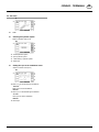
1000-GB DIRECT CONTROL_384
In general:
During operation the desired r.p.m of each individual
conditioner is monitored.
If the desired r.p.m. of a conditioner drops more than 180
min-1, a signal is heard and the LED of the respective button
on the switch panel blinks quickly (12, 13, 14).
Other settings
Monitoring the r.p.m. of the conditioner rotors
Elapsed time will start to be counted as soon as the r.p.m
of the p.t.o exceeds 300 min-1.
Elapsed time can be read on the LCD indicator inside the
job calculator housing.
Elapsed time is displayed in the following format
alternating with sensor diagnostics:
Elapsed time < 100:
14:36
Elapsed time < 100>
0346
Cancelling: When the r.p.m increases again, the whistling
and blinking passes at a slow rate. Only now can the
button be pushed (cancelling) and the whistling and
blinking will cease.
Note: In every instance the reason for the drop in r.p.m must
be eliminated otherwise cancelling cannot take place.
- Decrease speed,
- remove blockage,
- repair plug connection and cable.
- replace faulty sensor.
Monitoring only functions when the sensor is plugged in
and is not faulty.
The p.t.o is monitored in order to prevent any damage to
the cardan shaft when swinging the side mower unit out
over the field transport position
The button 11 function (road transportation)
can only be selected when the p.t.o sensor
hasn’t sent any impulses for at least 8
seconds.
- Drive shafts should no longer be turning.
Monitoring the r.p.m. of the p.t.o.
Elapsed time meter

GB”DIRECT CONTROL” DEVICE
- 19 -
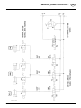
1000-GB DIRECT CONTROL_384
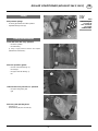
Setting time difference – Raising/lowering front mower and side mower
Note!
The set times
remain stored
until altered
Switching “time difference function” on/off:
Switching function on:
- Briefly press button 10 “I/O”
- The LEDs change colour to green
- By pressing button 15 all set time differences are
active
Switching function off:
- Briefly press button 10 “I/O”
- The LEDs change colour to red
- By pressing button 15 all mower units are
simultaneously raised or lowered
From 2007 model
Control with dual coloured light emitting diodes
(LEDs)
1. Change to other operation mode
- Briefly press button I/O
- the (LED) changes to green
2. Switch on programming mode:
- Press button 15 for 5 secs.
- The button LED should blink green
Setting time difference - raising
- Put control into programming mode
- Press button B1 (front mower raised)
To set the desired time difference keep pressing
button B1
- When button is released both side mowers are
raised and the time difference is stored.
- Programming mode ends automatically
Setting time difference - lowering
- Put control into programming mode
- Press button A1 (front mower lowered)
To set the desired time difference keep pressing
button A1
- When button is released both side mowers are
lowered and the time difference is stored
- Programming mode ends automatically

GB”DIRECT CONTROL” DEVICE
- 20 -
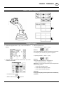
1000-GB DIRECT CONTROL_384
Conversion from operating to transport
position
1. Press button 15
2. Briefly press button B1
Mower units swing into the field transport position
(headland turns)
3. Press button 11
4. Press button B1 and hold
Mower units swing into road transport position
Conversion from transport to operating
position
1. Press button 15
2. Press button 11
3. Press button A1 and hold
Mower units swing into the field transport position
(headland turns FT)
4. Briefly press button A1
The mower units swing downwards (with delayed
action);
First the front mower, and then both side mowers; the
swivel cylinders remain in the floating position.
Conversion from working to transport position
Safety Precaution!
• Changing from working position to transport position is
only to be carried out on even, firm ground.
• Only transport the machine in the transport position!
• Before swivelling the cutter bar up, turn off the drive and wait
for the mower discs to come to a complete standstill.
• Make sure that swivel area is free and that nobody is
standing in the danger area.
Conversion from operating to field transport
position (headland turns FT)
1. Press button 15
2. Briefly press button B1
The mower units swing upwards (with delayed
action);
first the front mower, and then both side mowers
Conversion from the field transport position
(headland turns FT) to operating position
1. Button 15 must be activated (LED lights up)
2. Briefly press button A1
The mower units swing downwards (with delayed
action);
First the front mower, and then both side mowers; the
swivel cylinders remain in the floating position.
Important
Each mower unit
can also be
individually swung
upwards and
downwards.
1. Select desired
hydraulic function
(12, 13, 14)
2. Press button (A1,
B1)
La pagina si sta caricando...
La pagina si sta caricando...
La pagina si sta caricando...
La pagina si sta caricando...
La pagina si sta caricando...
La pagina si sta caricando...
La pagina si sta caricando...
La pagina si sta caricando...
La pagina si sta caricando...
La pagina si sta caricando...
La pagina si sta caricando...
La pagina si sta caricando...
La pagina si sta caricando...
La pagina si sta caricando...
La pagina si sta caricando...
La pagina si sta caricando...
La pagina si sta caricando...
La pagina si sta caricando...
La pagina si sta caricando...
La pagina si sta caricando...
La pagina si sta caricando...
La pagina si sta caricando...
La pagina si sta caricando...
La pagina si sta caricando...
La pagina si sta caricando...
La pagina si sta caricando...
La pagina si sta caricando...
La pagina si sta caricando...
La pagina si sta caricando...
La pagina si sta caricando...
La pagina si sta caricando...
La pagina si sta caricando...
La pagina si sta caricando...
La pagina si sta caricando...
La pagina si sta caricando...
La pagina si sta caricando...
La pagina si sta caricando...
La pagina si sta caricando...
La pagina si sta caricando...
La pagina si sta caricando...
La pagina si sta caricando...
La pagina si sta caricando...
La pagina si sta caricando...
La pagina si sta caricando...
La pagina si sta caricando...
La pagina si sta caricando...
La pagina si sta caricando...
La pagina si sta caricando...
La pagina si sta caricando...
-
 1
1
-
 2
2
-
 3
3
-
 4
4
-
 5
5
-
 6
6
-
 7
7
-
 8
8
-
 9
9
-
 10
10
-
 11
11
-
 12
12
-
 13
13
-
 14
14
-
 15
15
-
 16
16
-
 17
17
-
 18
18
-
 19
19
-
 20
20
-
 21
21
-
 22
22
-
 23
23
-
 24
24
-
 25
25
-
 26
26
-
 27
27
-
 28
28
-
 29
29
-
 30
30
-
 31
31
-
 32
32
-
 33
33
-
 34
34
-
 35
35
-
 36
36
-
 37
37
-
 38
38
-
 39
39
-
 40
40
-
 41
41
-
 42
42
-
 43
43
-
 44
44
-
 45
45
-
 46
46
-
 47
47
-
 48
48
-
 49
49
-
 50
50
-
 51
51
-
 52
52
-
 53
53
-
 54
54
-
 55
55
-
 56
56
-
 57
57
-
 58
58
-
 59
59
-
 60
60
-
 61
61
-
 62
62
-
 63
63
-
 64
64
-
 65
65
-
 66
66
-
 67
67
-
 68
68
-
 69
69


Pottinger NOVACAT 8600 Istruzioni per l'uso
- Categoria
- Tosa erba
- Tipo
- Istruzioni per l'uso
- Questo manuale è adatto anche per
in altre lingue
Documenti correlati
-
Pottinger EUROCAT 275 PLUS H Istruzioni per l'uso
-
-
-
-
-
-
-
-
-