
/PERATOR@S MANUAL
GB
).3425#4)/.3 &/2 02/$5#4 $%,)6%29 0AGE
4RANSLATION OF THE ORIGINAL /PERATING -ANUAL
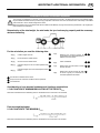
Ihre / Your / Votre • Masch.Nr. • Fgst.Ident.Nr.
.R
• Tedder
99 2181.GB.80K.0
HIT 610 N
( Type ZK 2181 : + . . 01001 )
HIT 610 NZ
( Type ZK 2181 : + . . 01001 )

ALLG./BA SEITE 2 / 0000-GB
Important information concerning Product
Liability.
According to the laws governing product liability, the manufacturer and dealer are obliged to hand the
operating manual to the customer at the time of sale, and to instruct them in the recommended operating,
safety, and maintenance regulations. Confirmation is necessary to prove that the machine and operating
manual have been handed over accordingly.
For this purpose,
- document A is to be signed and sent to Pöttinger,
- document B remains with the dealer supplying the machine,
- and the customer receives document C.
In accordance with the laws of product liability, every farmer is an entrepreneur.
According to the laws of product liability, property damage is damage caused by a machine and not to
it. An excess of Euro 500 is provided for such a liabilioty.
In accordance with the laws of product liability, entrepreneurial property damages are excluded from
the liability.
Attention! Should the customer resell the machine at a later date, the operating manual must be given
to the new owner who must then be instructed in the recommended regulations referred to herein.
GB Dear Farmer
You have just made an excellent choice. Naturally we are very happy
and wish to congratulate you for having chosen Pöttinger. As your
agricultural partner, we offer you quality and efficiency combined with
reliable servicing.
In order to assess the spare-parts demand for our agricultural machines
and to take these demands into consideration when developing new
machines, we would ask you to provide us with some details.
Furthermore, we will also be able to inform you of new developments.
Pöttinger Newsletter
www.poettinger.at/landtechnik/index_news.htm
The latest expert information, useful links and entertainment

Dokument D
GB-0600 Dokum D Anbaugeräte
PÖTTINGER Landtechnik GmbH
Industriegelände 1
A-4710 Grieskirchen
Tel. 07248 / 600 -0
Telefax 07248 / 600-2511
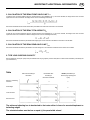
T Machine checked according to delivery note. All attached parts removed. All safety equipment, drive shaft and operating
devices at hand.
T Operation and maintenance of machine and/or implement according to operating instructions explained to the customer.
T Tyres checked re. correct pressure.
T Wheel nuts checked re. tightness.
T Drive shaft cut to correct lenght.
T *VYYLJ[WV^LY[HRLVɈZWLLKPUKPJH[LK
T Fitting to tractor carried out: to three-point linkage
T Trial run carried out and no defects found.
T Functions explained during trial run.
T Pivoting in transporting and operating position explained.
T Information given re. optional extras.
T Absolute need to read the operating manual indicated.
Please check. X
According to the product liability please check the above mentioned items.
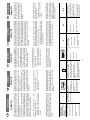
INSTRUCTIONS FOR
PRODUCT DELIVERY
GB
In order to prove that the machine and the operating manual have been properly delivered, a confirmation is necessary.
For this purpose please do the following:
- sign the document A and send it to the company Pöttinger or via the internet to www.poettinger.at
- document B stays with the specialist factory delivering the machine.
- document C stays with the customer.

- 4 -
TABLE OF CONTENTS
GB
0800_GB-INHALT_2181
Observe Safety Hints in the supplement!
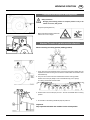
CE sign
The CE sign, which is affixed by the
manufacturer, indicates outwardly that
this machine conforms to the engineering
guideline regulations and the other relevant
EU guidelines.
EU Declaration of Conformity
By signing the EU Declaration of Conformity, the manufacturer declares
that the machine being brought into service complies with all relevant
safety and health requirements.
Meaning of warning signs
Never reach into the crushing danger area as long
as parts may move.
Do not enter rotor area while driving motor is
running.
Stay clear of swinging area of implements
495.173
Table of contents
CE sign .............................................................................................. 4
Meaning of warning signs ................................................................. 4
HITCHING
Hitching of machines with three point linkage .................................. 5
Locking the headstock during use on roads and when lowering ..... 5
Release rope ..................................................................................... 5
Connecting hydraulic system to the tractor ...................................... 5
Connecting hydraulic system to the tractor ...................................... 6
Note ................................................................................................... 6
LOWERING THE MACHINE
Lowering the rotary tedder ................................................................ 7
Cleaning of machine parts ................................................................ 7
Parking in the open ........................................................................... 7
Winter storage ................................................................................... 7
ADJUSTMENTS BEFORE OPERATION
Safety hints: ....................................................................................... 8
Adjustment of rotor inclination .......................................................... 8
Tine inclination .................................................................................. 8
Driving on public roads: .................................................................... 8
TRANSPORT POSITION
Driving on public roads ..................................................................... 9
Conversion from working to transport position ............................... 10
Locking the headstock during use on roads: ................................. 10
Warntafeln ....................................................................................... 11
Tableau de signalisation .................................................................. 11
Warning plates ................................................................................. 11
WORKING POSITION
Conversion from transport to working position ............................... 13
Attention! The order of operation must be adhered to .................... 13
USE
General guidelines for working ........................................................ 14
with the machine ............................................................................. 14
Operating on slopes ........................................................................ 14
Shock absorbtion struts .................................................................. 14
Adjustment ...................................................................................... 14
Setting lower link: .......................................................................... 14
Tractor control device (ST) .............................................................. 14
Clearing Ä eld edges (border tedding) to the left or to the right ....... 15
Tine adjustment ............................................................................... 16
MAINTENANCE
Maintenance and servicing ............................................................. 17
Intake transmission ......................................................................... 17
Changing tines ................................................................................ 17
Gas container .................................................................................. 17
Alteration of gas container pressure ............................................... 17
TECHNIC AL DATA
Technical data ................................................................................. 18
Necessary connections ................................................................... 18
The deÄ ned use of the rotary tedder ............................................... 18
Optional equipment ......................................................................... 18
Position of Vehicle IdentiÄ cation Plate ............................................ 18
SUPPLEMENT
Recommendations for work safety ................................................ 21
Driveshaft ........................................................................................ 22
Lubrication chart ............................................................................ 24
Lubricants ........................................................................................ 26
Montage van extra’s (Meerprijs) ...................................................... 28
Working with windrowing gear ....................................................... 28
Combination of tractor and mounted implement ............................ 29

GB
300-GB Anbau_218 - 5 -
HITCHING
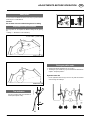
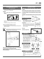
Hitching of machines with three point linkage
Safety hints:
see supplement-A1 points 7.), 8a. - 8h.)
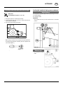
1. Pinning the machine to the three point linkage.
2. Fix the hydraulic lower link (4) in such a way that the machine
cannot swing out sideways.
3. Push in the support foot (5) and secure.
- Before using for the first time, the length of the drive shaft must
be checked and adjusted if necessary (see also supplement B
"Drive shaft adaption").
TD34/90/4
5
4
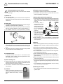
Locking the headstock during use on roads and
when lowering
For transport the headstock (SB) must be locked using a lock nut.
A = working position
B = transport position
Important!
Only reposition the lock pin when the machine is in the raised
position.
Release rope
- Run rope (S) into tractor
cabin.

HITCHING GB
300-GB Anbau_218 - 6 -
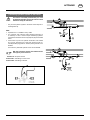
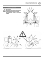
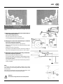
Connecting hydraulic system to the tractor
For reasons of accident prevention the p.t.o. must
be switched off and the rotors must come to a stand
still before raising the side rotors.
- Only connect hydraulic system to the tractor when stopcock is
closed (position A).
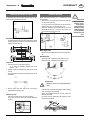
Note
• Hydraulic line L1 is available in every model.
• For machines with hydraulic wheel adjusting equipment it
is necessary to have a second simple functioning hydraulic
connection on the tractor. The two-way stopcock (H2) is connected
to this.
• If the tractor only has one hydraulic connection, then instead
of a two-way stopcock (H2), a three-way stopcock (order no.
445.059) and the plug (order no. 448.051) which goes with it can
be fitted.
This means any individual hydraulic circuit can be selected.
With this connection variation, the backflow choke
valve (D) may not be removed.
Position A: Stopcock closed.
Position E1: Swivelling of outer rotors.
Position E2: Swivelling of wheels.
TD12/93/15
L1
H2
A
E
D
TD12/93/14
445.059
448.051
L1
D
L1

- 7 -
0300-GB Abstellen_218
GB
LOWERING THE MACHINE
Cleaning of machine parts
Attention! Do not use high-pressure washers for the cleaning of
bearing- and hydraulic parts.
- Danger of rust!
- After cleaning, grease the machine according to the lubrication
chart and carry out a short test run.
- Cleaning with too high pressure may do damage to varnish.
Parking in the open
When parking for longer periods in
the open, clean plunger rods and
then coat with grease.
Check when parking
• So that rain water can run off unhindered,
the holes " W" must not be blocked.
Winter storage
- Thoroughly clean machine before storage.
- Put up protection against weather.
- Protect exposed parts from rust.
- Lubricate all greasing points according to lubrication chart.
- Park machine with liftet rotors, which will protect plunger from
rust.
FETT
TD 49/93/2
W
TD7/95/5
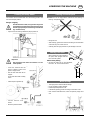
Lowering the rotary tedder
The machine can be lowered both from the working position and
from the transport position.
Danger of tipping
Park the machine on firm, level ground. If the ground
is soft then the area where the support foot is to stand
must be appropriately increased using a suitable aid
(e.g. wooden board).
- Unpin bolt on the slewing headstock (SB) in position A.
Important!
Only reposition bolts when the machine is in the
raised position.
- Lower the machine with the
tractor hydraulic system and
place on support foot.
- Pull off drive shaft and rest on
support.
Do not rest drive shaft on safety
chain!
- Close stopcock (position A).
- Unhitch machine from
tractor.
- Remove hydraulic cables.

- 8 -
9800-GB VOREINSTELLUNGEN (213)
GB
ADJUSTMENTS BEFORE OPERATION
Adjustment of rotor inclination
Running axles can be adjusted to different settings at the gearing
(A)
1 setting = 1° alteration to rotor inclination).
A lot of fodder = greater angle
Not much fodder = smaller angle
Tine inclination
It is also important that tine inclination is
correct (see chapter "USE").
S1S2
80
TD 16/96/2
R
Safety hints:
All work in the immediate area of the rotors may only be carried out
when the p.t.o. is switched off.
Caution!
Do not enter rotor area while driving motor is running.
495.173
Driving on public roads:
• Observe the official regulations of your country.
• Travelling on open roads may only be carried out as described in
chapter "Transport position".
Hydraulic lower link
- Fix the hydraulic lower link (4) in such a way that the machine
cannot swing out sideways.

0300-GB Transp (209) - 9a -
GB
TRANSPORT POSITION
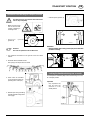
Driving on public roads
Safety Precaution!
Changing from working position to transport position
is only to be carried out on even, firm ground.
Only transport the machine in the transport
position!

TRANSPORT POSITION
0300-GB Transp (209) - 10a -
GB
Conversion from working to transport position
For safety reasons, turn off drive shaft and wait for
rotor to stop completely.
- Make sure that swivel
area is free and that
nobody is standing in
the danger area.
- Stopcock opened
(position E)
Attention!
The order of operation must be adhered to.
1. The implement must stand on the ground on the two centre
wheels.
2. EUROHIT 69 AZ, EUROHIT 80 AZ
Pull rope (S). The stop function is raised.
3. Outer rotors are swivelled
up into transport position by
operating servo-valve (ST).
4. Release rope during swivelling
procedure so that locking hooks
can engage.
- Close stopcock (position A).
Attention!
- Check whether the locking hooks (10) are locked into
position correctly.
Locking the headstock during use on roads:
For transport the headstock (SB) must be locked using a lock nut.
B = transport position
Important!
Only reposition the
lock pin when the
machine is in the
raised position.
10 10
TD48/91/3

209 / BELEUCHTUNG / 9600-D/F/GB - 11 -
BELEUCHTUNG
F
D
GB
ECLAIRAGE
REMOVABLE LIGHTNING
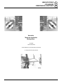
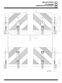
Warntafeln (D)
Tableau de signalisation (F)
Warning plates (GB)
Einzelteile
siehe Ersatzteilliste.
Pièces détachée voir liste des pièces de rechange.
For single parts see spare parts list.

209 / BELEUCHTUNG / 9600-D/F/GB - 12 -
BELEUCHTUNG
F
D
GB
ECLAIRAGE
REMOVABLE LIGHTNING

- 13 -
9500-GB ARBEITSSTELLUNG (209)
GB
WORKING POSITION
Conversion from transport to working position
Safety Precaution!
Changing from working position to transport position is only to be
carried out on even, firm ground.
- Stopcock opened (position E)
- Make sure that the swivelling area is free
and that no one is in danger.
Attention! The order of operation must be adhered to
When converting to working position (tedding position):
1. Firstly, lower the whole implement to the ground using the tractor's lifting gear. The
implement must stand on the ground on the two centre wheels with the outer rotors
still swivelled up.
2. Only now can the outer rotors be swivelled down into the working position.
Position servo-valve (ST) briefly at "lift" and simultaneously pull on rope (S).
In so doing, mechanical locks are eased.
3. Position tractor's servo-valve (ST) at "lower". The rotor is swivelled down to working
position.
4. Pin the bolts on the slewing headstock (SB) into position A.
Important!
Only reposition bolts when the machine is in the raised position.

- 14 -
0300-GB Einsatz_218
GB
USE
General guidelines for working
with the machine
All work in the immediate area of the rotors may only be carried
out when the p.t.o. is switched off.
Caution!
Do not enter rotor area while driving motor is
running.
- Choose the speed of travel so that all crops are picked up
thoroughly.
- In cases of overloading, shift down one gear.
Three-point slewing headstock "type N"
- Lift three point follower machine before going around sharp bends
and when reversing.
Beware!
Machine swings automatically back to central position
when lifted and is locked into position.
Take care that the swinging machine does not endanger
anybody and does not hit solid obstacles.
When lowering the machine the locking devise is
automatically lifted.
Operating on slopes
Take note! Machine with three-point slewing headstock
"type N"
If the implement is being raised by the lifting gear whilst travelling in
a curve, the implement swings automatically into the central position.
If working on slopes this can lead to dangerous situations, partly due
to the balance weight of the implement (tipping, slipping, material
breakage etc.).
The function of the shock absorbtion struts is to allow the swinging
procedure to be executed slowly and continuously, not in jerks and
jolts.
Shock absorbtion struts
(Optional extra)
Shock absorbtion struts (D) are
recommended for work on slopes
as they increase travel safety.
Adjustment
By turning the hexagonal nut (SK) the initial
tension of the disk spring and, with that, the
pressure on the friction elements (R) on the
rod can be altered.
Variation
(standard equipment)
Adjustment
- Adjust length of upper
link (9) so that rotors
are inclined forward
and spring tines lightly
touch the ground (see
chapter "Adjustment
of rotor inclination"
also). Check upper link
(9) adjustment regularly
during work operation.
Setting lower link:
- Tractor's lower link (U)
must be set so that there
is no sideways play in order
to prevent tedder from
swinging back and forth.
Tractor control
device (ST)
- Put tractor control device (ST) into
"free gear" (floating position or
"lower").
In this way the rotors adapt to uneven
ground.
495.173
SK
TD 75-98-15

USE
- 15 -
0300-GB Einsatz_218
GB
Clearing field edges (border tedding) to the left
or to the right
Clearing field edges can be carried out by swinging the runner
wheel.
1.) Swinging of a single runner wheel on machines without
central adjusting equipment
- Press down the adjusting lever (7).
- Swing the wheels to the right or to the left.
- Lock the adjusting lever into the desired position.
2.) Swinging the runner wheel hydraulically on machines
with central adjusting equipment
- Open stopcock (position E with two-way stopcock).
Position E1 when using a three-way stopcock (see also chapter
"HITCHING").
- Operate servo-valve on the tractor.
To swing the runner wheel left move servo-valve to "lift" position. To
swing runner wheel right move servo-valve to "lower" position.
3.) Swinging the runner wheel mechanically on machines
with central adjusting equipment
- Release locking bolts by pulling the rope (S).
- Turn the tractor wheels in the direction of the field edge and drive
forward at the same time. The machine's runner wheels swing
in the opposite direction.
- Let go of the rope (S) and make sure that the locking bolts are
correctly engaged.
Note
The slanting axles make border tedding possible with the three
point machines. In this working position the swivel area (9) is used
to its full extent.
When driving around bends away from the edge of the field or at the
end of the field, the machine must therefore be lifted.
Attention!
The machine swings back into the central position.

USE
- 16 -
0300-GB Einsatz_218
GB
Tine adjustment
Tine position can be altered by turning the tine carrier (80).
• Position "S1"
Standard position (ex factory)
• Position "S2"
For use under difficult conditions, e. g. with very dense, awkward
forage. This tine position increases the strewing action.
• Direction of rotation "R"
Be aware of this when installing tines.
S
1
S
2
80
TD 16/96/2
R
TD16/96/1
80

GB
- 17 -
0300-GB Wartung_218
MAINTENANCE
Maintenance and servicing
In order to keep the machine in good condition even after a longer
period of operation, please observe the following notes:
- After the first hours of operation, tighten all
screws.
In particular the tine connections (12 kpm), the tine bar connections
(9 kpm) and the slewing headstock connections should be
checked.
- Always keep the stipulated air pressure in the tyres.
- Grease the lubrication points in accordance with the regulation (see
lubrication schedule).
Grease the lubrication nipples with universal grease after every 20
hours of operation.
- Before leaving the machine over winter, oil all the joints well and
grease all bearings.
Intake transmission
The intake transmission runs in oil
which must be renewed or added to
after every year of operation:
- Pour gear lubricant oil into
the intake transmission (see
enclosure on fuel regulation).
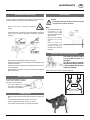
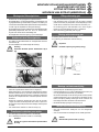
Changing tines
- Remove broken tine after loosening the hexagonal nut and fit new
tine.
- For correct fitting observe the direction of the rotors!
- Tighten hexagonal screw with 12 daNm (= 12 kpm).
- Fit the safety shackle correctly (longer side (6) outside)!
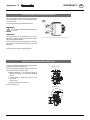
Gas container
Beware!
No welding, soldering or mechanical works of any kind
may be carried out on the container.
Note
• According to manufacturer's
information all gas
containers have a slight
pressure drop after a certain
amount of time.
• The gas loss (nitrogen)
amounts to 2-3 % per
year.
• After 4-5 years it is
recommended that
container pressure be
checked and if necessary
corrected.
Alteration of gas container pressure
This work may only be carried
out by customer service or a
specialist.
In order to reduce or increase
the pressure in the gas container
a special filling and checking
device is necessary.
Pressure in the gas container: 80 bar Nitrogen (N).
TD 7/95/3
Drehrichtung
direction of rotation
12 kpm

GB
- 18 -
0800-GB-Techn. Daten_2181
TECHNIC AL DATA
Position of Vehicle Identification Plate
The factory number is imprinted on the accompanying Vehicle
Identification Plate (as shown) and on the frame. Guarantee issues
and further inquiries cannot be processed without the factory number
being stated.
Please enter the number onto the front page of the operating manual
immediately after taking delivery of the vehicle/implement.
The defined use of the rotary tedder
The „
HIT 610 N/ NZ
“ rotary tedder is intended solely for normal use in agricultural work.
• For the tedding, turning and raking of green and raw fodder and silage.
Any other uses outside of these are regarded as undefined.
The manufacturer takes no responsibility for any resulting damage which occurs henceforth. The risk is carried by the user alone.
• The keeping of operating, service and maintenance requirements layed down by the manufacturer also come under the heading of „defined
use“.
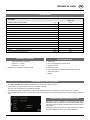
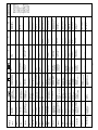
Technical data
Necessary connections
• 1 single-action hyfraulic connection
pressure min.: 100 bar
pressure max.: 180 bar
• 7-pole electric connection for lighting (12 Volt)
Optional equipment
• Feeler wheel
• Rear mounting assembly for feeler wheel
• Winding protection
• Mechanical locking
• Hydr. adjustment for boundary tedding attachment (AZ, NZ)
• Trailer rocker KAT I/II
• Lighting
All data subject to revision.
Description HIT 610 N / NZ
(Type 2181)
Machine width in working position [m] 6,00
Working width [m] 5,75
Transport width - folded up [m] 2,85
Maximum height [m] 2,97
Transport height [m] 3,50
Number of rotors 6
Tine arms per rotor 5
Diameter of rotor [m] 1,30
Required power [kW/PS] 20 / 27
P.t.o. speed max. [rpm] 540
Tyres at the rotors 15x6.00-6 4 Ply rating
Tyre pressure [bar] 1,5
Highest permitted speed [km/h] 30
Weight - with three-point swivel frame [kg] 670
Permanent Sound Emmission Level [db (A)] 71,3

GB-Anhang Titelblatt _BA-Allgemein
GB
SUPPLEMENT

GB-Anhang Titelblatt _BA-Allgemein
GB
The decision must be made, ”original” or ”imitation”? The decision is often governed
by price and a ”cheap buy” can sometimes be very expensive.
Be sure you purchase the ”Original” with the cloverleaf sym-
bol!
• Quality and precise fitting
- Operating safety.
• Reliable operation
• Longer lasting
- Economy
• Guaranteed availability through your
Pöttinger Sales Service.
Things will run better with
genuine Pöttinger parts
The original cannot be copied ...
La pagina si sta caricando...
La pagina si sta caricando...
La pagina si sta caricando...
La pagina si sta caricando...
La pagina si sta caricando...
La pagina si sta caricando...
La pagina si sta caricando...
La pagina si sta caricando...
La pagina si sta caricando...
La pagina si sta caricando...
La pagina si sta caricando...
La pagina si sta caricando...
La pagina si sta caricando...
-
 1
1
-
 2
2
-
 3
3
-
 4
4
-
 5
5
-
 6
6
-
 7
7
-
 8
8
-
 9
9
-
 10
10
-
 11
11
-
 12
12
-
 13
13
-
 14
14
-
 15
15
-
 16
16
-
 17
17
-
 18
18
-
 19
19
-
 20
20
-
 21
21
-
 22
22
-
 23
23
-
 24
24
-
 25
25
-
 26
26
-
 27
27
-
 28
28
-
 29
29
-
 30
30
-
 31
31
-
 32
32
-
 33
33


Pottinger HIT 610 NZ Istruzioni per l'uso
- Tipo
- Istruzioni per l'uso
- Questo manuale è adatto anche per
in altre lingue
Documenti correlati
-
Pottinger EUROHIT 81 NZ Istruzioni per l'uso
-
-
-
-
-
-
-
-
-