
/PERATOR@S MANUAL
GB
).3425#4)/.3 &/2 02/$5#4 $%,)6%29 0AGE
4RANSLATION OF THE ORIGINAL /PERATING -ANUAL
Ihre / Your / Votre • Masch.Nr. • Fgst.Ident.Nr.
.R
Drum mower
CAT 230 plus
(Type PTM 331 : + . . 01001)
CAT 230 plus Conditioner
(Type PTM 331 : + . . 01001)
99 331.GB.809.1

ALLG./BA SEITE 2 / 0000-GB
Important information concerning Product
Liability.
According to the laws governing product liability, the manufacturer and dealer are obliged to hand the
operating manual to the customer at the time of sale, and to instruct them in the recommended operating,
safety, and maintenance regulations. Confirmation is necessary to prove that the machine and operating
manual have been handed over accordingly.
For this purpose,
- document A is to be signed and sent to Pöttinger,
- document B remains with the dealer supplying the machine,
- and the customer receives document C.
In accordance with the laws of product liability, every farmer is an entrepreneur.
According to the laws of product liability, property damage is damage caused by a machine and not to
it. An excess of Euro 500 is provided for such a liabilioty.
In accordance with the laws of product liability, entrepreneurial property damages are excluded from
the liability.
Attention! Should the customer resell the machine at a later date, the operating manual must be given
to the new owner who must then be instructed in the recommended regulations referred to herein.
GB Dear Farmer
You have just made an excellent choice. Naturally we are very happy
and wish to congratulate you for having chosen Pöttinger. As your
agricultural partner, we offer you quality and efficiency combined with
reliable servicing.
In order to assess the spare-parts demand for our agricultural machines
and to take these demands into consideration when developing new
machines, we would ask you to provide us with some details.
Furthermore, we will also be able to inform you of new developments.

Dokument D
GB-0600 Dokum D Anbaugeräte - 3 -
ALOIS PÖTTINGER Maschinenfabrik GmbH
A-4710 Grieskirchen
Tel. (07248) 600 -0
Telefax (07248) 600-511
GEBR. PÖTTINGER GMBH
D-86899 Landsberg/Lech, Spöttinger-Straße 24
Telefon (0 81 91) 92 99-111 / 112
Telefax (0 81 91) 92 99-188
GEBR. PÖTTINGER GMBH
Servicezentrum
D-86899 Landsberg/Lech, Spöttinger-Straße 24
Telefon (0 81 91) 92 99-130 / 231
Telefax (0 81 91) 59 656
Q Machine checked according to delivery note. All attached parts removed. All safety equipment, drive shaft and operating
devices at hand.
Q Operation and maintenance of machine and/or implement according to operating instructions explained to the customer.
Q Tyres checked re. correct pressure.
Q Wheel nuts checked re. tightness.
Q Drive shaft cut to correct lenght.
Q Correct power-take-off speed indicated.
Q Fitting to tractor carried out: to three-point linkage
Q Trial run carried out and no defects found.
Q Functions explained during trial run.
Q Pivoting in transporting and operating position explained.
Q Information given re. optional extras.
Q Absolute need to read the operating manual indicated.
Please check. X
According to the product liability please check the above mentioned items.
INSTRUCTIONS FOR
PRODUCT DELIVERY
GB
In order to prove that the machine and the operating manual have been properly delivered, a confirmation is necessary.
For this purpose please do the following:
- sign the
document A and send it to the company Pöttinger
(in case of Landsberg equipment: to the company Landsberg)
- document B stays with the specialist factory delivering the machine.
- document C stays with the customer.

- 4 -
GB
Attention!
ÈÛìÞëïÞÌÚßÞíò
ÁâçíìâçíáÞ
ìîééåÞæÞçí¦º
ͺ»Å¾È¿¼ÈÇ;ÇÍÌ
TABLE OF CONTENTS
WARNING SIGNS
CE sign ........................................................................... 5
Meaning of warning signs .............................................. 5
TECHNICAL DATA
Technical data ............................................................... 6
Optional extra: ............................................................... 6
TRAKANBAU
Attachement ................................................................... 7
To swing mounting frame up .......................................... 7
Set lower link pin on mounting frame accordingly. ........ 8
Lower link pin (990mm - 1040mm) standard ................. 8
Lower link pin (940mm - 1090mm) optional .................. 8
ATTACHMENT
Hitch mower up to tractor ............................................9
How to use the jack stand ............................................ 10
Converting from operating to transport position .......... 11
Lighting during use on roads ........................................11
Changing from transport- to working position ........... 12
Parking the mower ....................................................... 12
TRANSPORT
Road Transport ............................................................. 13
Parking the machine ..................................................... 13
STARTING WORK
Important points befor starting work ............................ 14
Safety hints ................................................................... 15
CUTTING HEIGHT
Cutting height adjustment ........................................... 17
CONDITIONER
Mowing with the conditioner ....................................... 18
Dismounting/mounting the rotor .................................. 18
Mowing with the conditioner ....................................... 19
Dismounting/mounting the rotor .................................. 19
EXTRA DRY
"Extra dry" system........................................................20
Swathes ........................................................................ 20
Spread width ................................................................ 21
ANTI-HINDRANCE SAFETY DEVICE
Anti-hindrance safety device: ....................................... 22
Positioning: ................................................................... 22
Wartung und Pflege ...................................................... 23
Mowing discs ............................................................... 24
Conditioner ................................................................... 24
Putting away for the winter ..........................................25
Raising the frame ......................................................... 25
Schmierplan ................................................................. 27
Lubrication chart .......................................................... 27
SUPPLEMENT
Driveshaft ..................................................................... 31
Lubricants .................................................................... 33
Combination of tractor and mounted implement ......... 35

- 5 -
9700-GB AZB_330
GB
WARNING SIGNS
CE sign
The CE sign, which is affixed by the manufacturer, indicates outwardly that this machine conforms to the
engineering guideline regulations and the other relevant EU guidelines.
EU Declaration of Conformity (see supplement)
By signing the EU Declaration of Conformity, the manufacturer declares that the machine being brought
into service complies with all relevant safety and health requirements.
Meaning of warning signs
Danger - flying objects; keep safe distance from the machine as long as the engine is running.
Do not open or remove safety shields while engine is running
Wait until all machine components have completely stopped before touching them.
Stay clear of mower knife area as long as tractor engine is running with PTO connected.
Shut off engine and remove key before performing maintenance or repair work.
Stay clear of swinging area of implements
Never reach into the crushing danger area as long as parts may move.

- 6 -
9501_GB-TECHN. DATEN_331
GB
Technical data
Optional extra:
• Conditioner with driveshaft
• Swath disc
• Lamp carrier cpl.
TD41/90/40
TD 41/90/39
max. 30o
max. 20o
CAT 230 (Type PTM 331)
Working width 2,25 m
Coverage up to 2,5 ha/h
nu.of drums 2
no.of blades per drum 4
maximum power take-up at p.t.o. 44 KW(60 HP)
maximum power take-up with conditioner 59 KW(80 HP)
maximum p.t.o speed 540 rpm
transport width 1850 mm
transport heigth 2650 mm
weight 650 kg
weight with conditioner 820 kg
stope angle: - uphill approx. 30°
stope angle:-downhill aprox. 20°
Permanent sound emmission level 92,5 dB(A)
On data subject to revision.
TECHNICAL DATA

GB
- 7 -
9401-GB TRAKANBAU_330
TRAKANBAU
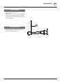
Attachement
TD 79/90/29
- Connect the Hydraulic socket gear (60) to the swivel cylinder.
- Pull out the supporting feet and secure them with the cotter
pin.
- Release hook (16) by means of the cord .
- By controlling the tractor servo-valve, lower the frame slowly.
To swing mounting frame up
Safety hints:
see supplement-A1 points 8a. - h.)

GB
TRAKANBAU
- 8 -
9401-GB TRAKANBAU_330
Set lower link pin on mounting frame accordingly.
Important: The mower must be aligned so that the edge of the tractor-side drum is just outside the right-hand tractor tyre.
Lower link pin (990mm - 1040mm) standard
Lower link pin (940mm - 1090mm) optional

- 9 -
9500_GB-ANBAU_331
GB
580 mm
TD20/91/1
ST-24-11-2003
Hitch mower up to tractor
Important: The mower must be aligred so that the edge
of the tractor-side drum is just outside the right-hand
tractor tyre.
- Unterlenkerbolzen am Anbaurahmen entsprechend
verstellen.
- After hitching the mower at the tractor’s 3 point linkage,
set it horizontal (as seen from behind) by adjusting
spindles (15) of the linkage arms.
- By twisting upper link spindle (16), cutting drums are
brought into a horizontal position or inclined slightly
forward.
- Set 3 point linkage with bottom stop (ST) so that the
lower links are approx. 580 mm high.
With this setting the mower can adjust perfectly to
uneven ground; it need not be changed for swinging
the cutter bar up.
ATTACHMENT

- 10 -
9500_GB-ANBAU_331
ATTACHMENT GB
TD79/90/25
2
2
2
2
2
2
2
TD79/90/24
2
- Make hydraulic plug connection for pivoting cylinder.
• Before using for the first time, the length of the drive
shaft must be checked and adjusted if necessary (see
also supplement B „Drive shaft adaption“).
How to use the jack stand
- Lift cutter bar with the tractor hydraulics.
- Raise jack stand with lever (2) and secure it with linch
pin.
How to use the jack stand for parking the
implement.
- Lift cutter bar with the tractor hydraulics
- Pull out jack stand with lever (2) and secure it with linch
pin.

- 11 -
9500_GB-TRANSPORT_331
TRANSPORT GB
Converting from operating to transport
position
- Lower the cutter bar on to ground.
- To release the hooks (40), pull on the cable and then
move forwards with the tractor. At the same time, the
cutter bar swivels back as far as possible until the
hooks (41) are locked into position.
- Gradually move cutter bar into vertical position.
- Secure cutter bar with lock (13).
- Always check lock is engaged correctly before every
road trip!
Important! never let the mowing mechanism
run with the mower raised
Lighting during use on roads
If desired, a lighting unit can be supplied.
For single parts see spare parts list.
- Connect lighting and raise appliance for transport.
- Before you leave the tractor, lower the cutter bar on to
ground.
TD41/90/33
TD41/90/40
27
26
TD 20/91/2
Safety Precaution!
Changing from
working position
to transport
position is only to
be carried out on
even, firm ground.

- 12 -
9500_GB-TRANSPORT_331
TRANSPORT GB
Changing from transport- to working
position
Swinging the cutter bar down.
1. Make sure that swivel area is free and that nobody is
standing in the danger area.
2. First raise the mower slightly the hydraulic cylinder, so
that you can release the lock.
3. Swing the cutter bar down.
Parking the mower
- Before you leave the tractor, lower the machine on to
ground!
- Before disconnecting hose (26) extend cylinder (27) fully,
so that no residuel pressure interferes with connecting
up later.
580 mm
TD20/91/1
27
26
TD 20/91/2
Safety Precaution!
Changing from
transport position
to working
position is only to
be carried out on
even, firm ground.

- 13 -
9500_GB-TRANSPORT_331
GB
Road Transport
• Observe the regulations issued by your country's
legislative body.
• Travelling on public roads may only be undertaken as
is described in the chapter "Transporting Position".
• Fasten lower hydraulic link so that implement cannot
swing out sideways.
Parking the machine
- When the implement ist parked, either remove the
driveshaft and store it, or secure it with a chain.
Do not use retaining chain (H) for this.
H
TD58/94/6
TRANSPORT

- 14 -
9800_GB-INBETRIEBNAHME_331
GB
Important points befor starting work
(see supplement-A1 points 1, 3 and 4)
Positioning (60 cm):
- The tractor hydraulics must be set to enable the mower
to adapt to uneven ground surfaces. This means that the
lowest hydraulic position (60 cm) must be limited.
- Mounting frame horizontal.
- Cutting drums horizontal or inclined slightly forward.
- Fix the hydraulic lower link in a way that the machine
can not swing out sideways.
60 cm
TD20/91/1a
TD79/90/33
STARTING WORK

- 15 -
9800_GB-INBETRIEBNAHME_331
STARTING WORK GB
- Check initial spring tension.
Adjustment settings:
530 mm without conditioner
490 mm with conditioner
Safety hints
1. Check:
- Check wear of blade bolt (31).
Replace blade holder when bolt diameter is less than
9 mm.
- Check blade holder (30) on damage.
- In case of grinding noises check whether the blade
holder (30) is buckled and therefore the blade does
not lie correctly any more.
2. Turn p.t.o. on.
Turn the p.t.o. on only when all safety
devices (coverings, protective aprons,
casings, etc.) are in proper condition and
attached to the implement in the correct
protective positions.
3. Switch-on the machine only in working position
and do not exceed the prescribed power take-
off speed (for example max. 540 rpm).
A transfer, which is located near the gear, advises which
p.t.o. speed your mower unit is equipped for.
540 Upm 1000 Upm
490 mm (mit CR)
530 mm (normal)
TD 20/98/03

- 16 -
9800_GB-INBETRIEBNAHME_331
STARTING WORK GB
4. Pay attention to correct p.t.o. direction of
rotation!
To mow, slowly throw in the p.t.o. away from the mowing
area and bring the mowing rotor up to full speed. The
travelling speed depends on ground contours and type
of forage.
5. Stay clear while engine is running
Refer people to the danger area, the danger coming
from stones which are flung away. Particular care
is advisable on stoney ground and near roads and
paths.
6. Wear hearing protection
The noise level in the workplace can deviate from the
measured value (see Technical Data) partly because
of the differing cabin types of various tractors.
• If a noise level of 85 dB (A) is reached or exceeded,
the farmer must have suitable hearing protection in
readiness (UVV 1.1 §2).
• If a noise level of 90 dB (A) is reached or exceeded,
the hearing protection must be worn (UVV 1.1 § 16).
7. Damage protection!
• The surface to be mowed must be free
of obstructions or foreign objects. Such
objects (e.g. large stones, pieces of wood,
boundary stones, etc.) can damage the
mower unit.
In the event of a collision
• Stop immediately and switch off the drive.
• Carefully check the implement for damage.
• Have the implement checked also by a specialist
workshop if necessary.
8. Safety hints (pt. 1, 2, 3, 4,) to observe in
supplement A1!
bsb 447 410

- 17 -
9500_GB-SCHNITTHÖHTE_331
GB
Cutting height adjustment
By adjusting the center disc (M), the cutting height can be
adjusted to any interval between 30 mm and 65 mm.
- Bring the pitch cutter bar into the vertical position and
lock (13).
For Your Safety:
Der Stützfuß (ST) soll am Boden aufstehen.
- Attach the accompanying key onto the square and
turn until the required cutting height is reset.
TD41/90/37
CUTTING HEIGHT

- 18 -
9900_GB-AUFBEREITER_330
GB
TD41/90/28
13
Mowing with the conditioner
- You can modify the conditioning effect with lever (13),
which adjusts the gap between adjustable plate and
rotor.
The conditioning effect is most inlense with the lever
at the buttom of its travel. However the crop should
not be chopped.
- With dense crops it may be advisable to shift the rotor
backwards, increasing the gap between rotor (21) and
intake ledge (24). To do this, undo bolts (S) on the left
and right of the mower.
Dinstance min.: 12 mm
Dismounting/mounting the rotor
Do not open cover while engine is
running.
- Release clamp and hinge up cover.
- Disconnect rotor driveshaft (22) and withdraw through
opening in canvas.
- Strike wedges (23) out apwards and pull rotor out to
the rear.
- Close discharge hood.
- Important: when mounting the rotors, position the two
grease nipples (9) on right and left into the recesses
in the aligning forkes, without damaging them. Secure
wedges (23) with leight blows of a hammer.
TD41/90/31
23
9
TD77/90/9
S
min. 12 mm
21
24
Variation (...-BJ 1998)
CONDITIONER

- 19 -
9900_GB-AUFBEREITER_330
CONDITIONER GB
TD41/90/31
23
9
TD41/90/28
13
Variation (...+BJ 1998)
Mowing with the conditioner
- You can modify the conditioning effect with lever (13),
which adjusts the gap between adjustable plate and
rotor.
The conditioning effect is most inlense with the lever
at the buttom of its travel. However the crop should
Dismounting/mounting the rotor
Do not open cover while engine is
running.
- Release clamp and hinge up cover.
- Disconnect rotor driveshaft (22) and withdraw through
opening in canvas.
- Strike wedges (23) out apwards and pull rotor out to
the rear.
- Close discharge hood.
- Important: when mounting the rotors, position the two
grease nipples (9) on right and left into the recesses
in the aligning forkes, without damaging them. Secure
wedges (23) with leight blows of a hammer.

9900-GB EXTRA DRY_330 - 20 -
GBEXTRA DRY
Variation
"Extra dry" system
Note
The settings listed below are to be understood as basic settings.
Because of the various types of crops, an optimum setting of the
guiding plates can possibly first be ascertained when the machine
is in use.
Swathes
1. Set the positions of the guiding plates
- see diagram
TD 79/99/06
12 3 4 5 6 7 8 9 10 11 12 13 14 15 16 17 18 19 20 21 22 23 24 25 26 27 28 29 30 31 32 33 34 35 36
La pagina si sta caricando...
La pagina si sta caricando...
La pagina si sta caricando...
La pagina si sta caricando...
La pagina si sta caricando...
La pagina si sta caricando...
La pagina si sta caricando...
La pagina si sta caricando...
La pagina si sta caricando...
La pagina si sta caricando...
La pagina si sta caricando...
La pagina si sta caricando...
La pagina si sta caricando...
La pagina si sta caricando...
La pagina si sta caricando...
La pagina si sta caricando...
La pagina si sta caricando...
La pagina si sta caricando...
La pagina si sta caricando...
-
 1
1
-
 2
2
-
 3
3
-
 4
4
-
 5
5
-
 6
6
-
 7
7
-
 8
8
-
 9
9
-
 10
10
-
 11
11
-
 12
12
-
 13
13
-
 14
14
-
 15
15
-
 16
16
-
 17
17
-
 18
18
-
 19
19
-
 20
20
-
 21
21
-
 22
22
-
 23
23
-
 24
24
-
 25
25
-
 26
26
-
 27
27
-
 28
28
-
 29
29
-
 30
30
-
 31
31
-
 32
32
-
 33
33
-
 34
34
-
 35
35
-
 36
36
-
 37
37
-
 38
38
-
 39
39


Pottinger CAT 230 PLUS ED Istruzioni per l'uso
- Tipo
- Istruzioni per l'uso
- Questo manuale è adatto anche per
in altre lingue
Documenti correlati
-
Pottinger EUROCAT 275 PLUS H Istruzioni per l'uso
-
-
-
-
-
-
-
-
-