Pepperl+Fuchs ML29-P/59/103/115 Istruzioni per l'uso
- Categoria
- Illuminazione di comodità
- Tipo
- Istruzioni per l'uso

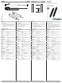
Abmessungen: Dimensions:
Construzione: Dimensiones:
alle Maße in mm
All dimensions are in mm
Tutte le dimensioni sono indicate in mm
Todas las dimensiones son en mm
Anschluss: Connection type:
Elettrici Allacciamento: Conexión:
Deutsch English ItaliaEspañol
Weitere Angaben siehe Katalog „Optoelektronische Sensoren“ For further information refer to the "Photoelectric Sensors"
catalogue
Per ulteriori dati vedere il catalogo "Sensori optoelettronici" Puede encontrar otras informaciones en el Catálogo "Sensores
fotoeléctricos"
Sicherheitshinweise:
• Vor der Inbetriebnahme Betriebsanleitung lesen
• Anschluss, Montage und Einstellung nur durch Fachper-
sonal
• Kein Sicherheitsbauteil gemäß EU-Maschinenrichtlinie,
darf nicht für Personenschutz oder NOT-AUS-Funktion
verwendet werden.
Technical data
Technische Daten Dati tecniciDatos técnicos
Security Instructions:
• Read the operating instructions before attempting
commissioning
• Installation, connection and adjustments should only be
undertaken by specialist personnel
• No safety component for protection of personnel or
EMERGENCY-STOP functions.
Avvertenze di sicurezza
• "Prima della messa in funzione, leggere le istruzioni per
l'uso.
• "Gli interventi di collegamento, montaggio e regolazione
devono essere effettuati solo da personale specializzato.
• "Non si tratta di un componente di sicurezza conforme
alla Direttiva UE "Macchine", pertanto non è consentito il
suo utilizzo per la protezione delle persone o per la
funzione di arresto d'emergenza.
Indicación de sguridad:
• Antes de la puesta en marcha leer las indicaciones de
uso.
• La conexión, el montaje y los ajustes deben roalizarse
sólo por personal cualificado.
• No es ningún elemento de seguridad según las normas
CE que pueda utilizarse para protección de personas o
como función de paro de emergencia.
Option:
WH
BN
BU
+UB
Q
0 V
103 Emitter
BN
BU
+UB
0V
Receiver
Function indicator,
LED red Transmitter
85.2
11.6
4.1
4.9 13.1
ø3.5
11.3
9.2
ø7.5
Einweg-Lichtschranke
Thru-beam sensor
Barriera ottica diretta
Sensor fotoeléctrico de barrera, unidireccional
ML29-P/59/103/115
Allgemeine Daten
Betriebsreichweite 0 ... 6 m
Grenzreichweite 8,5 m
Lichtsender IRED , 880 nm
Zulassungen CE
Lichtart infrarot, Wechsellicht
Öffnungswinkel +/- 8 °
Lichtaustritt seitlich
Fremdlichtgrenze 40000 Lux
Anzeigen/Bedienele-
mente
Funktionsanzeige LED rot im Empfänger : leuchtet bei Empfang
des Sendestrahls
Elektrische Daten
Betriebsspannung 11 ... 30 V DC
Leerlaufstrom I0Sender:
≤
25 mA
Empfänger:
≤
10 mA
Eingang
Testeingang Senderabschaltung bei +UB
≤
5 V DC
Ausgang
Schaltungsart dunkelschaltend
Signalausgang 1 PNP-Ausgang, kurzschlussfest, verpolsi-
cher, offener Kollektor
Schaltspannung max. 30 V DC
Schaltstrom max. 0,1 A
Schaltfrequenz f 100 Hz
Ansprechzeit 5 ms
Normenkonformität
Normen EN 60947-5-2
Normen 2 EN 61000-6-2
Normen 3 EN 61000-6-3
Umgebungsbedingungen
Umgebungstemperatur -20 ... 60 °C (253 ... 333 K)
Lagertemperatur -20 ... 75 °C (253 ... 348 K)
Relative Luftfeuchtigkeit 90 % , nicht kondensierend
Mechanische Daten
Schutzart IP65
Anschluss Festkabel 6 m
Material
Gehäuse PMMA , schwarz
Lichtaustritt Kunststoffscheibe
Masse je Gerät 12 g
General specifications
Effective detection range 0 ... 6 m
Threshold detection range 8.5 m
Light source IRED , 880 nm
Approvals CE
Light type infrared, modulated light
Angle of divergence +/- 8 °
Optical face lateral
Ambient light limit 40000 Lux
Indicators/operating
means
Function display LED red in receiver : lights up, when receiving
the light beam
Electrical specifications
Operating voltage 11 ... 30 V DC
No-load supply current I0Emitter:
≤
25 mA
Receiver:
≤
10 mA
Input
Test input emitter deactivation at +UB
≤
5 V DC
Output
Switching type dark ON
Signal output 1 PNP output, short-circuit proof, protected
from reverse polarity, open collector
Switching voltage max. 30 V DC
Switching current max. 0.1 A
Switching frequency f 100 Hz
Response time 5 ms
Standard conformity
Standards EN 60947-5-2
Standards 2 EN 61000-6-2
Standards 3 EN 61000-6-3
Ambient conditions
Ambient temperature -20 ... 60 °C (253 ... 333 K)
Storage temperature -20 ... 75 °C (253 ... 348 K)
Relative humidity 90 % , non-condensing
Mechanical specifications
Protection degree IP65
Connection fixed cable 6 m
Material
Housing PMMA , black
Optical face Plastic pane
Mass per device 12 g
Dati generali
Distanza della portata 0 ... 6 m
Portata limite 8,5 m
Trasmettitore fotoelettrico IRED , 880 nm
Omologazioni CE
Tipo di luce infrarosso, luce variabile
Angolo di apertura +/- 8 °
Uscita luce di lato
Limite luce estranea 40000 Lux
Indicatori / Elementi di
comando
Indicatore delle funzioni LED rosso nel ricevitore : si illumina in caso di
ricezione del raggio emesso
Dati elettrici
Tensione di esercizio 11 ... 30 V DC
Corrente a vuoto I0Trasmittente:
≤
25 mA
Ricevitore:
≤
10 mA
Ingresso
Ingresso di test Disinserzione trasmettitore con +UB
≤
5 V DC
Uscita
Tipo di circuito commutazione sullo scuro
Uscita del segnale 1 uscita pnp, a prova di cortocircuito, polarità
protetta, collettore aperto
Tensione di comando max. 30 V DC
Corrente di comando max. 0,1 A
Frequenza di commutazione f 100 Hz
Tempo di reazione 5 ms
Conformità alle norme
Norme EN 60947-5-2
Norme 2 EN 61000-6-2
Norme 3 EN 61000-6-3
Condizioni ambientali
Temperatura ambiente -20 ... 60 °C (253 ... 333 K)
Temperatura di magazzinag-
gio
-20 ... 75 °C (253 ... 348 K)
Umidità relativa dell'aria 90 % , senza condensa
Dati meccanici
Classe di protezione IP65
Allacciamento Cavo fisso 6 m
Materiale
Involucro PMMA , nero
Uscita luce Disco di plastica
Massa per apparecchio 12 g
Datos generales
Distancia útil operativa 0 ... 6 m
Distancia útil límite 8,5 m
Emisor de luz IRED , 880 nm
Certificados CE
Tipo de luz Infrarrojo, luz alterna
Angulo de apertura +/- 8 °
Salida de luz lateral
Límite de luz extraña 40000 Lux
Elementos de indicación
y manejo
Indicación de la función LED rojo en receptor : se ilumina si recibe
haces del receptor
Datos eléctricos
Tensión de trabajo 11 ... 30 V CC
Corriente en vacío I0emisor:
≤
25 mA
Receptor:
≤
10 mA
Entrada
Entrada de Test Desconexión del emisor en +UB
≤
5 V DC
Salida
Tipo de conmutación conmutación oscuro
Señal de salida 1 salida PNP, prot. ctra. cortocircuito, prot.
ctra. inversión de polaridad, colector abierto
Tensión de conmutación máx. 30 V CC
Corriente de conmutación máx. 0,1 A
Frecuencia de conmutación f 100 Hz
Tiempo de respuesta 5 ms
Conformidad con están-
dar
Estándar EN 60947-5-2
Estándar 2 EN 61000-6-2
Estándar 3 EN 61000-6-3
Condiciones ambientales
Temperatura ambiente -20 ... 60 °C (253 ... 333 K)
Temperatura de almacenaje -20 ... 75 °C (253 ... 348 K)
Humedad del aire relativa 90 % , no condensado
Datos mecánicos
Tipo de protección IP65
Conexión Cable fijo 6 m
Material
Carcasa PMMA , negro
Salida de luz Luneta de plástico
Masa por aparato 12 g
9. April 2008
Date: DIN A3 -> DIN
Part. No.: 129315 Doc. No.: 45-0902D

Adressen / Addresses / Adresses / Direcciónes / Indirizzi
Contact Pepperl+Fuchs GmbH · Königsberger Allee 87 · 68307 Mannheim · Germany · Tel. +49 621 776-4411 · Fax +49 621 776-27-4411 · E-mail: fa-info@de.pepperl-fuchs.com
Worldwide Headquarters: Pepperl+Fuchs GmbH · Mannheim · Germany · E-mail: info@de.pepperl-fuchs.com
USA Headquarters: Pepperl+Fuchs Inc. · Twinsburg · USA · E-mail: sales@us.pepperl-fuchs.com
Asia Pacific Headquarters: Pepperl+Fuchs Pte Ltd · Singapore · E-mail: sales@sg.pepperl-fuchs.com
For more contact-adresses refer to the catalogue or internet: http://www.pepperl-fuchs.com
Zusätzliche Informationen, Kennlinien, Hinweise
Informazioni, caratteristiche, avvertenze aggiuntive
Additional information; characteristic curves, notes
Información adicional, lineas caracteristicas, notas
Funktion
Die Einweg-Lichtschranke der Serie ML29 benötigt zum Betrieb ein Gerätepaar, bestehend aus einem Lichtsender und einem Licht-
empfänger. Sender und Empfänger müssen zueinander optisch in einer Linie ausgerichtet werden. Das vom Sender ausgestrahlte
Infrarot-Licht wird vom Empfänger erfasst und ausgewertet.
Statische Erfassung:
Die Lichtschranke erkennt Personen und Gegenstände unabhängig von Bewegung und Oberflächenstruktur solange, wie ein Ob-
jekt den Detektionsstrahl unterbricht.
Optik:
Die relativ weiten Öffnungswinkel erlauben ein schnelles Montieren der Lichtschranken ohne Ausrichtprobleme. Auch bei leichtem
Verzug von Montageprofilen bleibt die Funktion erhalten.
Testung:
Die Testung dient zur Funktionsprüfung der Lichtschranke.
Bei einer Betriebsspannung +UB < 5 V schaltet der Sender ab und simuliert damit eine Lichtstrahlunterbrechung. Hierdurch kann
auf einen separaten Testeingang verzichtet werden.
Montage:
Die Lichtschranke passt dank ihrer kleinen Abmessungen in U-Profile oder hinter beliebige Abdeckungen. Der Lochdurchmesser
beträgt beim Sender und beim Empfänger jeweils 8 mm.
Auch eine Befestigung mittels des zum Lieferumfang gehörenden Klebestreifens kann in Erwägung gezogen werden.
Montage bei zweistrahliger Absicherung :
Für eine zweistrahlige Version werden je 2 Sender und Empfänger benötigt. Dabei ist zu beachten, dass der minimale Strahlenab-
stand 20 cm beträgt. Sender und Empfänger müssen über Kreuz angeordnet werden.
Fehlersuche:
• Betriebsspannung messen
• Anschlüsse kontrollieren
• Mechanische Ausrichtung überprüfen
• Montage überprüfen
Function
The Series ML29 single path light beam switch requires a pair of devices for operation, comprising a light emitter and a light receiver.
The emitter and receiver must be arranged in optical alignment with each other. The infrared light from the emitter is detected by
the receiver and evaluated.
Static detection:
The light beam switch detects persons and objects independently of movement and surface structure for as long as the object
breaks the detection beam.
Optics:
The relatively wide opening angles enable the light beam switches to be installed quickly, without alignment problems. Even if there
is a light distortion of the installation profiles the function is retained.
Testing:
Testing is used to check the function of the light beam switch.
With supply voltage +UB < 5 V the emitter device is switched off. This simulates a light beam interruption. By means of this, the
function of the light barrier can be tested easily without using a separate test input.
Installation:
Thanks to its small dimensions, the light beam can be fitted in a U-profile or behind a face panel.The hole diameter for both the
emitter and the receiver is 8 mm.
Even fixing by means of the adhesive tape contained in the delivery package can be considered.
Installation of twin-beam arrangement:
A twin-beam version requires 2 emitters and receivers. Care should be taken that the beam separation is not less than 20 cm. The
transmitters and receivers must be arranged in the form of a cross.
Trouble shooting:
• Measure the operating voltage
• Check the connections
• Check the mechanical alignment
• Check the installation
Función
El sensor fotoeléctrico de barrera unidireccional Serie ML29 consta para trabajar de dos elementos, compuestos de un emisor y
un receptor de luz. Emisor y receptor deben estar colocados uno frente otro siguiendo una línea óptica. La luz infrarroja, emitida
por el emisor, se detecta y evalúa por el receptor.
Detección estática:
La barrera óptica reconoce a personas y objetos, independientemente del movimiento o de la naturaleza de la superficie, funcio-
nará siempre mientras un objeto interrumpa el haz de detección.
Optica:
Los ángulos de apertura relativamente anchos permiten un montaje rápido de las barreras ópticas sin problemas de ajuste. Incluso
con una ligera desviación de los perfiles de montaje se mantiene la función intacta.
Test:
El test sirve para la comprobación de la función de las barreras ópticas.
Con una tensión de trabajo +UB < 5 V el emisor se apaga y simula una interrrupción del haz. Gracias a esto se puede renunciar a
una entrada de test por separado.
Montaje:
La barrera óptica encaja en un perfil en U debido a sus pequeñas o detrás de cualquier cubierta. El diámetro del agujero es de
8 mm, en emisor y en receptor, cada uno.
Es posible también una fijación mediante un adhesivo, incluido con el suministro.
Montaje con fusible de dos haces :
Para una versión de dos haces se requieren 2 conjuntos de emisores y receptores. Ha de observarse que la distancia entre haces
sea de 20 cm mínimo. Los emisores y receptores hay que montarlos de forma cruzada.
Búsqueda de errores:
• medir tensión de trabajo
• controlar Conexiones
• comprobar Ajuste mecánico
• comprobar Montaje
Funzionamento
La barriera ottica diretta della serie ML29 necessita, per il funzionamento, di una coppia di dispositivi composta da trasmettitore
ottico e ricevitore ottico. Trasmettitore e ricevitore devono essere allineati otticamente. La luce infrarossa emessa dal trasmettitore
viene rilevata e interpretata dal ricevitore.
Rilevamento statico
La barriera ottica è in grado di riconoscere persone e oggetti indipendentemente dal movimento e dalla struttura superficiale quando
il raggio di rilevamento viene interrotto.
Ottica
Gli angoli di apertura relativamente ampi consentono una rapida installazione delle barriere ottiche senza problemi di allineamento.
Il funzionamento rimane inalterato anche in caso di leggera deformazione dei profili di montaggio.
Controllo
Il controllo ha lo scopo di verificare il funzionamento delle barriere ottiche.
Con tensione di alimentazione pari a +UB < 5 V il trasmettitore si disattiva, simulando un'interruzione del raggio luminoso. In tal
modo non è necessario un test di ingresso separato.
Installazione
Grazie alle misure ridotte, la barriera ottica è indicata nelle guide a U o dietro qualsiasi copertura. Nel trasmettitore e nel ricevitore
il diametro del foro misura 8 mm.
Possibile anche il fissaggio mediante la banda adesiva compresa nella fornitura.
Installazione con protezione a due raggi
Per la versione a due raggi sono necessari 2 trasmettitori e 2 ricevitori. In tal caso, accertarsi che la distanza minima dei raggi sia
pari a 20 cm. Trasmettitori e ricevitori devono essere disposti a croce.
Individuazione delle anomalie
• Misurare la tensione di alimentazione.
• Controllare le connessioni
• Verificare l'allineamento meccanico
• Verificare l'installazione
Zustand Elektronik
Hellschaltung /25 Person im Strahl nicht aktiv
keine Person im Strahl aktiv
Dunkelschaltung /59 Person im Strahl aktiv
keine Person im Strahl nicht aktiv
Status Electronics
Light detection /25 Person in the beam inactive
no Person in the beam active
Dark detection /59 Person in the beam active
no Person in the beam inactive
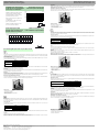
01234567891011
700
600
500
400
300
200
100
0
X [m]
Y [mm] ML29
X
Y
Charakteristische Ansprechkurve
Courbe de response caractéristique
Curve di risposta caratteristica
Characteristic response curve
Curva de respuesta característica
Möglicher Abstand (Versatz) zwischen
optischer Achse und Retroreflektor.
Permissible distance (offset) between
optical axis and retro-reflector.
Ecart possible entre l'axe optique et le
rétroréflecteur.
Desplazamiento posible entre el eje
óptico y el retroreflector.
Distanza possibile (sfalsato) tra l´asse
del sensore ed il retroriflettore.
01234567891011
100000
10000
1000
100
10
1
Funktionsreserve, Stability control, Réserve de fonctionnement,
Reserva de función, Funzione riserva
ML29
X [m] x
Relative Empfangslichtstärke
Intensité relative de la lumière reçue
Intensità relativa luce in ricezione
Relative received light strength
Potencia relativa de recepción lumínica
Beschreibung/Desciption/Descripción/Descrizione
E2
S1
S2
E1
min. 20 cm
min. 20 cm
max. 6 m
Electrónica
Conmutación claro /25 Persona en el haz inactivo
ninguna persona en el haz activo
Conmutación oscura /59 Persona en el haz activo
ninguna persona en el haz inactivo
Elettronica
Inserzione in presenza di luce /25 Persona nel raggio non attiva
Nessuna persona nel raggio attiva
Inserzione in assenza di luce /59 Persona nel raggio attiva
Nessuna persona nel raggio non attiva
E2
S1
S2
E1
min. 20 cm
min. 20 cm
max. 6 m
E2
S1
S2
E1
min. 20 cm
min. 20 cm
max. 6 m
E2
S1
S2
E1
min. 20 cm
min. 20 cm
max. 6 m
-
 1
1
-
 2
2


Pepperl+Fuchs ML29-P/59/103/115 Istruzioni per l'uso
- Categoria
- Illuminazione di comodità
- Tipo
- Istruzioni per l'uso
in altre lingue
Documenti correlati
-
Pepperl+Fuchs ML29-P/25/102/143 Istruzioni per l'uso
-
-
-
-
-
-
-
-
-