
3057
ROTAPULS
Incremental encoders
Series CB62
Complete documentation
at www.lika.biz
Warning: encoders having order code ending with "/Sxxx" may have mechanical and electrical characteristics different from standard and be supplied with additional documentation for special connections (Technical Info).
Attenzione: gli encoder con codice di ordinazione finale “/Sxxx” possono avere caratteristiche meccaniche ed elettriche diverse dallo standard ed essere provvisti di documentazione aggiuntiva per cablaggi speciali (Technical info).
Achtung: Geräte, deren Bestellschlüssel mit der Kennung /Sxxx enden, können in ihren mech. und elektr. Eigenschaften vom Standard abweichen. Diese werden daher mit einer ergänzenden Dokumentation ausgeliefert (Technical info).
Atención: los encoders con código de pedido acabado en "/Sxxx" pueden tener características mecánicas y eléctricas diferentes a las básicas y documentación adicional relativa a conexiones especiales (Technical Info).
Attention: les codeurs avec code de commande terminant en “/Sxxx” peuvent avoir des caractéristiques mécaniques et électriques différentes du standard et documentation additionnelle pour les câblages spéciaux (Technical info).
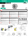
EN Mounting instructions (standard version) IT Istruzioni di montaggio (versione standard) DE Montagehinweise (Standardversion)
Assembly of the encoder
Remove the PG cap 1 from the back of the encoder;
fit the encoder into the rotor shaft 2 and fix it by means of the supplied M5 x
50 UNI 5931 screw 3; recommended tightening torque: 5 Nm;
replace the PG cap 1 properly and fix it;
tighten the M3 screw 4 to cause the flange 5 to expand so clamping the
encoder onto the stator 6; recommended tightening torque: 1.2 Nm.
Montaggio encoder
Svitare il tappo PG 1 posto sul retro dell'encoder;
montare l’encoder sull’albero del rotore 2 e fissarlo con la vite M5 x 50 UNI
5931 3 in dotazione; coppia di serraggio raccomandata: 5 Nm;
riposizionare e avvitare il tappo PG 1 precedentemente rimosso;
stringere la vite M3 4 procurando l'espansione della flangia 5 e il fissaggio
dell'encoder allo statore 6; coppia di serraggio raccomandata: 1,2 Nm.
Montage des Gebers
PG Deckel 1 von der Geberrückseite entfernen;
Geber auf die Rotorwelle 2 setzen und mit einer M5 x 50 UNI 5931 Schraube 3
(im Lieferumfang) festschrauben. Empfohlener Drehmoment max. 5 Nm;
PG Deckel 1 wieder sorgfältig aufsetzen und festziehen;
Spreizflansch 5 mit Hilfe der M3 Spannschraube 4 am Motor festklemmen.
Empfohlener Drehmoment max. 1,2 Nm.
Disassembly of the encoder
Unscrew the M3 screw 4 to release the expansion flange 5;
remove the PG cap 1 from the back of the encoder;
hold the rotor shaft 2 and screw off the M5 screw 3 which fixes the encoder
to the rotor shaft 2;
WARNING: do not force the encoder manually to remove it from
the motor!
carefully pull the encoder out of the rotor shaft 2 by screwing an
M6 screw in the encoder shaft. To prevent damage of the M5 thread we
recommend an M5 grub screw to be screwed in before using the M6 screw.
Smontaggio encoder
Svitare la vite 4 allentando così la flangia a espansione 5;
togliere il tappo PG 1 sul retro del dispositivo;
impedire che l'albero rotore 2 ruoti e rimuovere la vite M5 3 che fissa l'encoder
all’albero rotore 2;
ATTENZIONE: non forzare manualmente l’encoder per estrarlo dal
motore!
estrarre l'encoder dall’albero rotore 2 avvitando con prudenza una
vite M6 nell’albero encoder. Per non rovinare la filettatura dell’albero rotore 2
avvitare un grano M5 nell’albero rotore 2 prima di usare la vite M6.
Demontage des Gebers
Spannschraube 4 aufdrehen bis sich die Klemmung löst;
PG Deckel 1 von der Geberrückseite entfernen;
Rotorwelle 2 halten und dabei die M5 Schraube 3 zur Befestigung des Gebers
herausschrauben;
ACHTUNG: den Geber bei der Demontage nicht mechanisch
belasten!
Geber durch einschrauben der M6 Schraube mit Vorsicht von der
Rotorwelle 2 abziehen. Um gegen Schaden am M5 Gewinde vorzubeugen kann
ein M5 Gewindestift vor der M6 Schraube eingeschraubt werden.
ES Instrucciones de montaje (versión estándar) FR Instructions de montage (version standard)
Montaje de l'encoder
Aflojar la tapa PG 1 en la parte posterior del encoder;
montar el encoder en el eje del rotor 2 y asegurarlo mediante el tornillo 3 tipo
M5 x 50 UNI 5931; par de apriete recomendado: 5 Nm;
apretar de nuevo la tapa PG 1;
atornillar el tornillo tipo M3 4 para dilatar la brida 5 que asegura l'encoder al
estátor 6; par de apriete recomendado: 1,2 Nm.
Montage du codeur
Dévisser le couvercle PG 1 dans la partie postérieure du codeur ;
monter le codeur sur l'arbre du rotor 2 et le fixer au moyen de la vis 3 type M5
x 50 UNI 5931 ; couple de serrage recommandé : 5 Nm ;
visser de nouveau le couvercle PG 1 ;
visser la vis type M3 4 au fin d’étendre la bride d'expansion 5 qui fixe le codeur
au stator 6 ; couple de serrage recommandé : 1.2 Nm.
Desmontaje de l'encoder
destornillar el tornillo tipo M3 4 y aflojar la brida de expansión 5;
quitar la tapa PG 1 en la parte posterior del encoder;
asegurarse de que el eje del rotor 2 esté parado y destornillar el tornillo 3 tipo
M5 que fija el encoder en el eje del rotor 2;
ATTENCIÓN: no forzar manualmente el encoder para sacarlo del
motor!
atornillar con cuidado un tornillo tipo M6 en el eje del encoder
hasta la extracción completa del dispositivo de su alojamiento. Para evitar
daños en la rosca del eje rotor 2 aconsejamos apretar un tornillo sin cabeza
tipo M5 en el eje rotor 2 antes de que se utiliza el tornillo tipo M6.
Démontage du codeur
Dévisser la vis type M3 4 et relâcher la bride d'expansion 5 ;
ôter le couvercle PG 1 dans la partie postérieure du codeur ;
s'assurer que l'arbre du rotor 2 ne tourne pas et enlever la vis 3 type M5 qui
fixe le codeur à l'arbre du rotor 2 ;
ATTENTION: ne pas forcer le codeur manuellement pour l'extraire
du moteur !
extraire le codeur de l'arbre du rotor 2 en vissant une vis type M6
dans l'arbre du codeur ; dans le but de ne pas endommager le filetage de
l'arbre du rotor 2, on conseille de visser un boulon sans tête type M5 dans
l'arbre du rotor 2 avant d'utiliser la vis type M6.
Cable shield connection. We suggest gathering the shielding wires together
and fixing them by means of a hexagonal metal gland crimped 25 mm from the
connector. Be sure that the gland is in tight contact with the encoder's
enclosure. Prevent the shielding wires from coming in contact with the internal
electronics.
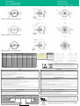
CB62 encumbrance sizes (A order code)
CB62 encumbrance sizes (standard version)

www.lika.biz Lika Electronic
Tel. +39 0445 806600 Via S.Lorenzo, 25
Fax +39 0445 806699 36010 Carrè (VI) - Italy
Electrical connections 98414-G06-14-LF
Function 14-pin connector EC-ASB/CB62-xx cable / cavo / Kabel / cable / câble male frontal side
C * 1 Violet Viola Violett Morado Violet maschio lato contatti
A3 Red Rosso Rot Rojo Rouge Aufsicht Stiftseite
/D * 4 Pink Rosa Rosa Rosado Rose macho lado contactos
0Vdc 5 White_Green Bianco_Verde Weiß_Grün Blanco_Verde Blanc_Vert mâle côté contacts
/B 6 Brown Marrone Braun Marrón Marron Pins 2 & 10 = not connected
07 White Bianco Weiß Blanco Blanc
/0 8 Blue Blu Blau Azul Bleu A/B = sin-cos incremental signals, 2048 sin periods/rev. 0 = zero signal, 1 pulse/rev.
B9 Green Verde Grün Verde Vert C/D * = sin-cos absolute Z track, 1 sin period/rev. * /1 option only, see the order code
D * 11 Grey Grigio Grau Gris Gris
/A 12 Black Nero Schwarz Negro Noir Installation has to be carried out with power supply disconnected.
L’installazione deve essere eseguita in assenza di tensione.
Der Anschluss darf nur bei ausgeschalteter Versorgungsspannung erfolgen.
La instalación sólo debe ser efectuada en ausencia total de tensión.
Le montage du dispositif doit être effectué en absence totale de tension.
+5Vdc ±5% 13 Brown_Green Marrone_Verde Braun_Grün Marrón_Verde Marron_Vert
/C * 14 Yellow Giallo Gelb Amarillo Jaune
Shield Shield Shield Schermo Schirm Malla Blindage
EC-ASB/CB62-xx connection cable available on request. To be ordered separately. Available length xx = 1 m, 4 m or 7 m.
Safety Avvertenze
Always adhere to the professional safety and accident prevention regulations applicable to your country during device installation and operation;
installation has to be carried out by qualified personnel only, with power supply disconnected and stationary mechanical parts;
the encoder must be used only for the purpose appropriate to its design: use for purposes other than those for which it has been designed could
result in serious personal and/or the environment damage;
high current, voltage and moving mechanical parts can cause serious or fatal injury;
warning ! Do not use in explosive or flammable areas;
failure to comply with these precautions or with specific warnings elsewhere in this manual violates safety standards of design, manufacture,
and intended use of the equipment;
Lika Electronic assumes no liability for the customer's failure to comply with these requirements.
Durante l’installazione e l’utilizzo del dispositivo osservare le norme di prevenzione e sicurezza sul lavoro previste nel proprio paese;
l’installazione deve essere eseguita da personale qualificato, in assenza di tensione e parti meccaniche in movimento;
utilizzare il dispositivo esclusivamente per la funzione per cui è stato costruito: ogni altro utilizzo potrebbe risultare pericoloso per l'utilizzatore;
alte correnti, tensioni e parti meccaniche in movimento possono causare lesioni serie o fatali;
non utilizzare in ambienti esplosivi o infiammabili;
il mancato rispetto delle norme di sicurezza o delle avvertenze specificate in questo manuale è considerato una violazione delle norme di
sicurezza standard previste dal costruttore o richieste dall'uso per cui lo strumento è destinato;
Lika Electronic non si assume alcuna responsabilità per eventuali danni o lesioni derivanti dall'inosservanza delle norme di sicurezza da parte
dell'utilizzatore.
Electrical safety Avvertenze elettriche
Turn OFF power supply before connecting the device;
connect according to explanation in the ”Electrical connections” section;
wires of output signals which are not used must be insulated singularly;
in compliance with 2014/30/EU norm on electromagnetic compatibility, following precautions must be taken:
- before handling and installing the equipment, discharge electrical charge from your body and tools which may come in touch with the device;
- power supply must be stabilized without noise; install EMC filters on device power supply if needed;
- always use shielded cables (twisted pair cables whenever possible);
- avoid cables runs longer than necessary;
- avoid running the signal cable near high voltage power cables;
- mount the device as far as possible from any capacitive or inductive noise source; shield the device from noise source if needed;
- to guarantee a correct working of the device, avoid using strong magnets on or near by the unit;
- minimize noise by connecting the shield and/or the frame to ground. Make sure that ground is not affected by noise. The connection point to
ground can be situated both on the device side and on user’s side. The best solution to minimize the interference must be carried out by the user.
Effettuare le connessioni elettriche esclusivamente in assenza di tensione;
rispettare le connessioni riportate nella sezione “Electrical connections”;
i fili dei segnali d’uscita non utilizzati devono essere isolati singolarmente;
in conformità alla normativa 2014/30/UE sulla compatibilità elettromagnetica rispettare le seguenti precauzioni:
- prima di maneggiare e installare il dispositivo, eliminare la presenza di carica elettrostatica dal proprio corpo e dagli utensili che verranno in
contatto con il dispositivo;
- alimentare il dispositivo con tensione stabilizzata e priva di disturbi, se necessario, installare appositi filtri EMC all’ingresso dell’alimentazione;
- utilizzare sempre cavi schermati e possibilmente “twistati”;
- non usare cavi più lunghi del necessario; evitare di far passare il cavo dei segnali del dispositivo vicino a cavi di potenza;
- installare il dispositivo il più lontano possibile da eventuali fonti di interferenza o schermarlo in maniera efficace;
- per garantire un funzionamento corretto del dispositivo, evitare l'utilizzo di apparecchiature con forte carica magnetica in prossimità dell'unità;
- collegare la calza del cavo e/o il corpo del dispositivo a un buon punto di terra; assicurarsi che il punto di terra sia privo di disturbi. Il
collegamento a terra può essere effettuato sul lato dispositivo e/o sul lato utilizzatore; è compito dell’utilizzatore valutare la soluzione migliore
da adottare per minimizzare i disturbi.
Mechanical safety Avvertenze meccaniche
Install the device following strictly the information in the “Mounting instructions” section;
mechanical installation has to be carried out with stationary mechanical parts;
do not disassemble the device; do not tool the device or its shaft;
delicate electronic equipment: handle with care; do not subject the device and the shaft to knocks or shocks;
respect the environmental characteristics of the product.
Montare il dispositivo rispettando rigorosamente le istruzioni riportate nella sezione “Istruzioni di montaggio”;
effettuare il montaggio meccanico esclusivamente in assenza di parti meccaniche in movimento;
non disassemblare il dispositivo; non eseguire lavorazioni meccaniche sul dispositivo;
dispositivo elettronico delicato: maneggiare con cura; evitare urti o forti sollecitazioni sia all’albero che al corpo del dispositivo;
utilizzare il dispositivo in accordo con le caratteristiche ambientali dello stesso.
Order code (example)
CB62 - V - 2048 /1 1 C10 xxx
1Vpp sine cosine V Additional code
Resolution (PPR) Shaft diameter (mm)
without C/D absolute sinusoidal pulses (absolute Z track) 0 1 +5Vdc ±5% supply voltage
with C/D absolute sinusoidal pulses (absolute Z track) 1
Refer to the technical catalogue for the available combinations.
This device is to be supplied by a Class 2 Circuit or Low-Voltage Limited Energy or Energy Source
not exceeding 30 Vdc. Refer to the order code for supply voltage rate.
Ce dispositif doit être alimenté par un circuit de Classe 2 ou à très basse tension ou bien en
appliquant une tension maxi de 30Vcc. Voir le code de commande pour la tension d'alimentation.
Lika Electronic reserves the right to make changes in specifications without prior notice – Lika Electronic si riserva il
diritto di apportare modifiche senza preavviso - Die Fa. Lika Electronic behält sich das Recht zu Änderungen ohne
Vorankündigung vor - Informaciones pueden ser modificadas por Lika Electronic sin previo aviso – Les informations
peuvent être modifiées par Lika Electronic sans avis préalable QR CB62 1220
Dispose separately
CB62 encumbrance sizes (B order code)
CB62 encumbrance sizes (E order code)
CB62 encumbrance sizes (D order code)
-
 1
1
-
 2
2


in altre lingue
- English: Lika CB62 Reference guide
- français: Lika CB62 Guide de référence
- español: Lika CB62 Guia de referencia
Documenti correlati
-
Lika CB59 Guida di riferimento
-
-
-
-
-
-
-
Lika MSC41 A Manuale utente
-
-
Altri documenti
-
SICK EKS36-2…, EKM36-2... Motor feedback system rotary HIPERFACE DSL® Istruzioni per l'uso
-
SICK SKS/SKM36S, safety Motor feedback system rotary HIPERFACE® Istruzioni per l'uso
-
-
 SICK STEGMANN DFS60S Pro Istruzioni per l'uso
-
-
