IEI Integration AFL4-W13-EHL Manuale utente
- Categoria
- Schede madri
- Tipo
- Manuale utente
Questo manuale è adatto anche per

AFL4-W10/W12/12/W13-EHL Panel PC
Page 1
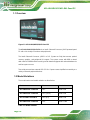
User Manual
AFL4-W10/W12/12/W13-EHL
MODEL:
Panel PC equips Intel® Celeron® J6412 on-board processor,
8GB LPDDR4X on-board, IEEE 802.11 a/b/g/n/ax, Bluetooth V5.2,
one M.2 2242 M key Slot, one M.2 2242 M key Slot
MODEL:
AFL4-W10/W12/12/W13-EHL
Rev. 1.00 - May 29, 2023
User Manual

AFL4-W10/W12/12/W13-EHL Panel PC
Page 2
Revision
Date
Version
Changes
May 29, 2023
1.00
Initial release

AFL4-W10/W12/12/W13-EHL Panel PC
Page 3
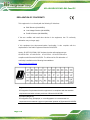
Safety Instructions
Warning! Read the user manual before connecting the system to the power
source.
Vorsicht! Bitte lesen Sie die Bedienungsanleitung, bevor Sie das System an eine
Stromquelle anschließen.
Attention! Avant de brancher le système à la source d'alimentation, consultez le
mode d'emploi.
Avvertenza! Consultare il manuale utente prima di collegare il sistema
all'alimentatore.
Atención! Lea atentamente este manual del usuario antes de operar la fuente de
alimentación.
警告!在將系統連接到電源之前,請仔細閱讀使用手冊。
警告!在将系统连接到电源之前,请仔细阅读使用手册。
Warning! To prevent the system from overheating, do not operate it in an area that
exceeds the maximum operating temperature described in the user manual.
Vorsicht! Um eine Überhitzung des Systems zu vermeiden, betreiben Sie es
ausschließlich im zulässigen Betriebstemperaturbereich. Dieser ist in der
Bedienungsanleitung vermerkt.
Attention! Pour éviter la surchauffe du système, ne l'utilisez pas dans une zone
dont la température dépasse les limites décrits dans le mode d'emploi.
Avvertenza! Per evitare che il sistema si surriscaldi, non utilizzarlo in aree che
superino la temperatura massima d'esercizio descritta nel manuale utente.
Atención! Para evitar el excesivo calentamiento del sistema, no opere en las
condiciones de temperatura superior a lo recomendado en este manual del
usuario.
警告!為防止系統過熱,不要在超過使用手冊上記載的產品工作溫度範圍之外操作
此系統。
警告!为防止系统过热,不要在超过使用手册上记载的产品工作温度范围之外操作
此系统。

AFL4-W10/W12/12/W13-EHL Panel PC
Page 4
Warning! Use only the adapter and power cord approved for this system. Use of
another type of adapter may risk fire or explosion. Please refer to the user manual
for the power adapter specifications.
Vorsicht! Nur zugelassene Netzteile und Netzkabel dürfen verwendet werden. Die
Benutzung von anderen Netzteilen kann einen Brand oder eine Explosion zur
Folge haben. Prüfen Sie die jeweiligen Spezifikationen in der
Bedienungsanleitung.
Attention! Utilisez exclusivement le câble d'alimentation et l’adaptateur
homologués pour ce système. L’utilisation d’un autre type d’adaptateur risquerait
de provoquer un incendie ou une explosion. Veuillez référer au mode d'emploi
pour les spécifications de l'adaptateur d'alimentation.
Avvertenza! Utilizzare solo l'adattatore e il cavo di alimentazione approvati per
questo sistema. L'uso di un altro tipo di adattatore può causare rischio d'incendio
o esplosione. Si prega di fare riferimento al manuale utente per le specifiche
sull'alimentazione.
Atención! Utilice solamente el adaptador de corriente alterna (CA) con Marcas
Conformidad otorgadas. Cualquier otro adaptador no otorgado aumenta el riesgo
de explosión o incendio. Por favor consulte el manual del usuario para las
especificaciones del adaptador de alimentación.
警告!只能使用經過認證、適用於本系統的電源變壓器與電源線。使用不適用的電
源變壓器將可能導致火災或爆炸。電源變壓器規格請參考使用手冊。
警告!只能使用经过认证,适用于本系统的电源适配器与电源线。使用不适用的电
源适配器将可能导致火灾或爆炸。电源适配器规格请参考使用手册。
Warning! Ultimate disposal of this product should be handled according to all
national laws and regulations.
Vorsicht! Die Entsorgung dieses Produkts sollte gemäß allen Bestimmungen und
Gesetzen des Landes erfolgen.
Attention! La mise au rebut ou le recyclage de ce produit sont généralement
soumis aux lois et/ou directives de respect de l'environnement. Renseignez-vous
auprès de l'organisme compétent.
Avvertenza! Lo smaltimento di questo prodotto deve essere eseguito secondo le
leggi e i regolamenti locali.
Atención! La disposición final de residuos de este producto se debe cumplir con
las normativas y leyes del país.
警告!本產品的廢棄處理應根據該國家的法律和規章進行。
警告!本产品的废弃处理应根据该国家的法律和规章进行。

AFL4-W10/W12/12/W13-EHL Panel PC
Page 5
Copyright
COPYRIGHT NOTICE
The information in this document is subject to change without prior notice in order to
improve reliability, design and function and does not represent a commitment on the part
of the manufacturer.
In no event will the manufacturer be liable for direct, indirect, special, incidental, or
consequential damages arising out of the use or inability to use the product or
documentation, even if advised of the possibility of such damages.
This document contains proprietary information protected by copyright. All rights are
reserved. No part of this manual may be reproduced by any mechanical, electronic, or
other means in any form without prior written permission of the manufacturer.
TRADEMARKS
All registered trademarks and product names mentioned herein are used for identification
purposes only and may be trademarks and/or registered trademarks of their respective
owners.

AFL4-W10/W12/12/W13-EHL Panel PC
Page 6
Manual Conventions
WARNING
Warnings appear where overlooked details may cause damage to the
equipment or result in personal injury. Warnings should be taken
seriously.
CAUTION
Cautionary messages should be heeded to help reduce the chance of
losing data or damaging the product.
NOTE
These messages inform the reader of essential but non-critical
information. These messages should be read carefully as any directions
or instructions contained therein can help avoid making mistakes.
HOT SURFACE
This symbol indicates a hot surface that should not be touched without
taking care.

AFL4-W10/W12/12/W13-EHL Panel PC
Page 7
Table of Contents
1 INTRODUCTION ........................................................................................................ 15
1.1 OVERVIEW................................................................................................................ 16
1.2 MODEL VARIATIONS ................................................................................................ 16
1.3 FEATURES ................................................................................................................. 17
1.4 FRONT PANEL........................................................................................................... 17
1.5 REAR PANEL ............................................................................................................ 17
1.6 BOTTOM PANEL ....................................................................................................... 18
1.7 SYSTEM SPECIFICATIONS .......................................................................................... 19
1.7.1 WLAN/Bluetooth Frequency Range and Power ............................................... 21
1.8 DIMENSIONS ............................................................................................................. 22
1.8.1 AFL4-W10-EHL Dimensions ........................................................................... 22
1.8.2 AFL4-W12-EHL Dimensions ........................................................................... 23
1.8.3 AFL4-12-EHL Dimensions .............................................................................. 24
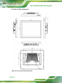
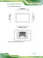
1.8.4 AFL4-W13-EHL Dimensions ........................................................................... 25
2 UNPACKING ............................................................................................................... 26
2.1 UNPACKING .............................................................................................................. 27
2.2 PACKING LIST .......................................................................................................... 28
2.3 OPTIONAL ITEMS ...................................................................................................... 29
3 INSTALLATION ......................................................................................................... 30
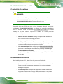
3.1 ANTI-STATIC PRECAUTIONS ...................................................................................... 31
3.2 INSTALLATION PRECAUTIONS ................................................................................... 31
3.3 INSTALLATION AND CONFIGURATION STEPS ............................................................. 32
3.4 REMOVING THE BACK COVER .................................................................................. 32
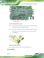
3.5 M.2 MODULE INSTALLATION .................................................................................... 33
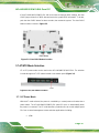
3.6 CLEAR CMOS .......................................................................................................... 34
3.7 AT/ATX MODE SELECTION ...................................................................................... 35
3.7.1 AT Power Mode ................................................................................................ 35
3.7.2 ATX Power Mode ............................................................................................. 36
3.8 MOUNTING THE SYSTEM .......................................................................................... 36

AFL4-W10/W12/12/W13-EHL Panel PC
Page 8
3.8.1 Wall Mounting .................................................................................................. 36
3.8.2 Arm Mounting .................................................................................................. 39
3.8.3 Stand Mounting ................................................................................................ 41
3.8.4 V-Stand Mounting ............................................................................................ 41
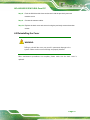
3.9 POWERING ON THE SYSTEM ...................................................................................... 43
3.10 RESET THE SYSTEM ................................................................................................ 44
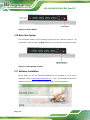
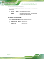
3.11 SOFTWARE INSTALLATION ...................................................................................... 44
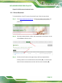
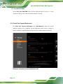
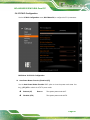
3.11.1 Driver Download............................................................................................ 45
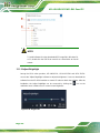
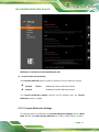
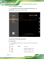
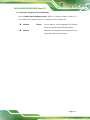
3.11.2 Adjust Brightlight ........................................................................................... 46
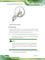
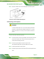
4 SYSTEM MAINTENANCE ....................................................................................... 47
4.1 SYSTEM MAINTENANCE INTRODUCTION .................................................................. 48
4.2 ANTI-STATIC PRECAUTIONS ...................................................................................... 48
4.3 TURN OFF THE POWER .............................................................................................. 49
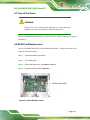
4.4 WLAN CARD REPLACEMENT .................................................................................. 49
4.5 REINSTALLING THE COVER ....................................................................................... 51
5 BIOS .............................................................................................................................. 52
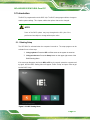
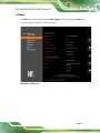
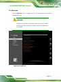
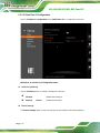
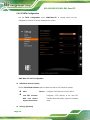
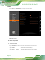
5.1 INTRODUCTION ......................................................................................................... 53
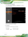
5.1.1 Starting Setup ................................................................................................... 53
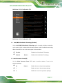
5.1.2 Using Setup ...................................................................................................... 54
5.1.3 Getting Help ..................................................................................................... 56
5.1.4 Unable to Reboot after Configuration Changes .............................................. 56
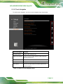
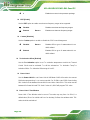
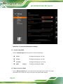
5.1.5 BIOS Menu Bar ................................................................................................ 56
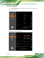
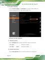
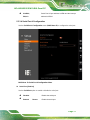
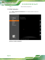
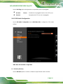
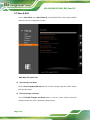
5.2 MAIN ........................................................................................................................ 57
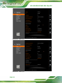
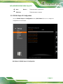
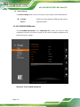
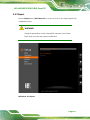
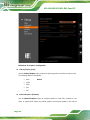
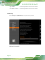
5.3 ADVANCED ............................................................................................................... 61
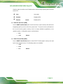
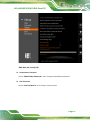
5.3.1 CPU Configuration .......................................................................................... 62
5.3.2 Trusted Computing ........................................................................................... 66
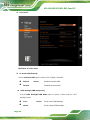
5.3.3 F81966 Super IO Configuration ...................................................................... 67
5.3.4 EC KB9068 H/W Monitor ................................................................................ 74
5.3.5 Serial Port Console Redirection ...................................................................... 78
5.3.6 NVMe Configuration ........................................................................................ 82
5.4 CHIPSET ................................................................................................................... 83
5.4.1 System Agent (SA) Configuration .................................................................... 84
5.4.2 PCH-IO Configuration .................................................................................... 89

AFL4-W10/W12/12/W13-EHL Panel PC
Page 9
5.5 SECURITY ................................................................................................................. 96
5.6 BOOT ........................................................................................................................ 98
5.6.1 Boot Configuration .......................................................................................... 98
5.6.2 Boot Option Priorities ...................................................................................... 99
5.7 SAVE & EXIT .......................................................................................................... 100
6 CONNECTORS ......................................................................................................... 102
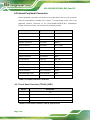
6.1 PERIPHERAL INTERFACE CONNECTORS ................................................................... 103
6.2 INTERNAL PERIPHERAL CONNECTORS .................................................................... 104
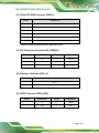
6.2.1 Touch Panel Connector (TOUCH_USB1) ..................................................... 104
6.2.2 Flash SPI ROM Connector (JBIOS1) ............................................................ 105
6.2.3 EC Debug Port Connector (EC_DEBUG1) .................................................. 105
6.2.4 Speaker Connector (SPK_L1) ........................................................................ 105
6.2.5 RFID Connector (RFID_USB1) .................................................................... 105
6.2.6 Digital MIC Connector (DMIC1) .................................................................. 106
6.2.7 I²C Connector (I2C1) ..................................................................................... 106
6.2.8 SMBus Connector (SMB1) ............................................................................. 106
6.2.9 Battery Connector (BAT1) ............................................................................. 106
6.2.10 M.2 A-Key Slot (M2_AE1) ........................................................................... 106
6.2.11 M.2 M-Key Slot (M2_M1) ............................................................................ 108
6.2.12 M.2 M-Key Slot (M2_M2) ............................................................................ 109
6.2.13 eDP Connector (EDP1) ................................................................................ 110
6.2.14 LVDS Connector (LCD1) .............................................................................. 111
6.2.15 LVDS Backlight Power (INV1) ..................................................................... 111
6.2.16 CPU Fan Connector (CPU_FAN1)............................................................... 112
6.3 JUMPER LESS SETTING ............................................................................................. 112
6.3.1 PWM Power Selection (J_PWM1) .................................................................. 112
6.3.2 Backlight Enable Selection (J_BL_EN) .......................................................... 112
6.3.3 Backlight VCC Selection (J_BL_VCC) ........................................................... 113
6.3.4 LVDS Power Selection (J_VLVDS1) ............................................................... 113
6.3.5 Flash Descriptor Security Override ................................................................ 113
6.4 EXTERNAL INTERFACE PANEL CONNECTORS ........................................................... 113
6.4.1 RS-232/422/485 Serial Ports (COM1/2/3/4) .................................................. 114
6.4.2 RJ45 LAN Connector (J_LAN1/2) .................................................................. 114
6.4.1 HDMI Connector (HDMI1) ............................................................................ 114

AFL4-W10/W12/12/W13-EHL Panel PC
Page 10
6.4.2 USB 2.0 Connectors (USB2_CON1/2/3) ........................................................ 115
6.4.3 USB 3.2 Gen 2 Connectors (USB3_CON12) .................................................. 115
6.4.4 Power Button (PWR_SW1) ............................................................................. 116
6.4.5 DC Jack ........................................................................................................... 116

AFL4-W10/W12/12/W13-EHL Panel PC
Page 11
List of Figures
Figure 1-1: AFL4-W10/W12/12/W13 Panel PC ............................................................................16
Figure 1-2: Front View ..................................................................................................................17
Figure 1-3: Rear View ...................................................................................................................18
Figure 1-4: Front Bottom Panel ...................................................................................................18
Figure 1-5: Left Bottom Panel .....................................................................................................18
Figure 1-6: Right Bottom Panel ...................................................................................................19
Figure 1-7: AFL4-W10-EHL Dimensions (mm) ...........................................................................22
Figure 1-8: AFL4-W12-EHL Dimensions (mm) ...........................................................................23
Figure 1-9: AFL4-12-EHL Dimensions (mm) ..............................................................................24
Figure 1-10: AFL4-W13-EHL Dimensions (mm) .........................................................................25
Figure 3-1: Back Cover Retention Screws .................................................................................33
Figure 3-2: Remove the Back Cover ...........................................................................................33
Figure 3-3: M.2 Module Slot Location .........................................................................................34
Figure 3-4: M.2 Module Installation .............................................................................................34
Figure 3-5: Clear CMOS Button Location ...................................................................................35
Figure 3-6: AT/ATX Switch Location ...........................................................................................35
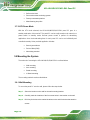
Figure 3-7: Wall-mounting Bracket .............................................................................................37
Figure 3-8: Chassis Support Screws ..........................................................................................38
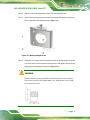
Figure 3-9: Secure the Panel PC .................................................................................................39
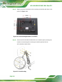
Figure 3-10: Arm Mounting Retention Screw Holes ..................................................................40
Figure 3-11: Arm Mounting ..........................................................................................................40
Figure 3-12: Stand Mounting (Stand-Cxx) ..................................................................................41
Figure 3-13: Drill Pilot Holes for V-Stand ...................................................................................42
Figure 3-14: Secure V-Stand to System .....................................................................................42
Figure 3-15: Secure V-Stand to Mounting Area .........................................................................43
Figure 3-16: Power Button ...........................................................................................................44
Figure 3-17: Reset Button Location ............................................................................................44
Figure 3-18: IEI Resource Download Center ..............................................................................45
Figure 3-19: Keypad AP ...............................................................................................................46
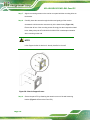
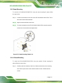
Figure 4-1: WLAN Module Location ............................................................................................49
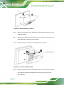
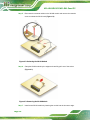
Figure 4-2: Releasing the WLAN Module ...................................................................................50

AFL4-W10/W12/12/W13-EHL Panel PC
Page 12
Figure 4-3: Removing the WLAN Module ...................................................................................50
Figure 5-1: BIOS Starting Menu ..................................................................................................53
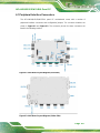
Figure 5-1: Main Board Layout Diagram (Front Side) .............................................................103
Figure 5-2: Main Board Layout Diagram (Solder Side) ...........................................................103

AFL4-W10/W12/12/W13-EHL Panel PC
Page 13
List of Tables
Table 1-1: Model Variation ...........................................................................................................16
Table 1-2: System Specifications ................................................................................................21
Table 1-3: WLAN/Bluetooth Frequency Range and Power.......................................................21
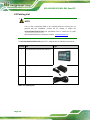
Table 2-1: Packing List .................................................................................................................28
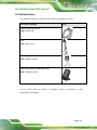
Table 2-2: Optional Items .............................................................................................................29
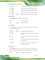
Table 5-1: BIOS Navigation Keys ................................................................................................54
Table 5-2: BIOS On-screen Navigation Keys .............................................................................55
Table 5-1: Peripheral Interface Connectors .............................................................................104
Table 5-2: Touch Panel Connector (TOUCH_USB1) Pinouts .................................................104
Table 5-3: Flash SPI ROM Connector (JBIOS1) Pinouts.........................................................105
Table 5-4: EC Debug Port Connector (EC_DEBUG1) Pinouts ...............................................105
Table 5-5: Speaker Connector (SPK_L1) Pinouts ...................................................................105
Table 5-6: RFID Connector (RFID_USB1) Pinouts ...................................................................105
Table 5-7: Digital MIC Connector (DMIC1) Pinouts .................................................................106
Table 5-8: I²C Connector (I2C1) Pinouts ...................................................................................106
Table 5-9: SMBus Connector (SMB1) Pinouts .........................................................................106
Table 5-10: Battery Connector (BAT1) Pinouts .......................................................................106
Table 5-11: M.2 A-Key Slot (M2_AE1) Pinouts .........................................................................108
Table 5-12: M.2 M-Key Slot (M2_M1) Pinouts ..........................................................................109
Table 5-13: M.2 M-Key Slot (M2_M2) Pinouts ..........................................................................110
Table 5-14: eDP Connector (EDP1) Pinouts .............................................................................111
Table 5-15: LVDS Connector (LCD1) Pinouts ..........................................................................111
Table 5-16: LVDS Backlight Power (INV1) Pinouts .................................................................112
Table 5-17: CPU Fan Connector (CPU_FAN1) Pinouts ...........................................................112
Table 5-18: Jumper less Setting ................................................................................................112
Table 5-19: PWM Power Selection (J_PWM1) ..........................................................................112
Table 5-20: Backlight Enable Selection (J_BL_EN) ................................................................112
Table 5-21: Backlight VCC Selection (J_BL_VCC) ..................................................................113
Table 5-22: LVDS Power Selection (J_VLVDS1) ......................................................................113
Table 5-23: Flash Descriptor Security Override ......................................................................113
Table 5-24: External Interface Panel Connectors ....................................................................113

AFL4-W10/W12/12/W13-EHL Panel PC
Page 14
Table 5-25: External Serial Port Connector (COM1/2/3/4) Pinouts ........................................114
Table 5-26: LAN Connector (J_LAN1/2) Pinouts .....................................................................114
Table 5-27: HDMI1 Connector (HDMI1) Pinouts .......................................................................115
Table 5-28: USB 2.0 Connectors (USB2_CON1/2/3) Pinouts ..................................................115
Table 5-29: USB 3.2 Gen 2 Connectors (USB3_CON12) Pinouts ...........................................115
Table 5-30: Power Button (PWR_SW1) Pinouts ......................................................................116
Table 5-31: DC Jack Connector .................................................................................................116

AFL4-W10/W12/12/W13-EHL Panel PC
Page 15
1 Introduction
Chapter
1

AFL4-W10/W12/12/W13-EHL Panel PC
Page 16
1.1 Overview
Figure 1-1: AFL4-W10/W12/12/W13 Panel PC
The AFL4-W10/W12/12/W13-EHL is an Intel® Celeron® Processor J6412 powered panel
PC with a rich variety of functions and peripherals.
The Intel® Celeron® Processor J6412 is a SoC (System-on-Chip) that ensures optimal
memory, graphics, and peripheral I/O support. The system comes with 8GB on-board
dual-channel LPDDR4x RAM ensuring smooth data throughputs with reduced bottlenecks
and fast system access.
Two serial ports and two external USB 3.2 Gen 2 ports ensure simplified connectivity to a
variety of external peripheral devices.
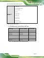
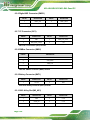
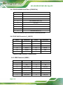
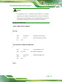
1.2 Model Variations
The model number and model variation are listed below.
Model
Size
Resolution
AFL4-W10-EHL-J1/8G-R10
10.1”
1280 x 800
AFL4-W12-EHL-J1/8G-R10
12.1” (16:10)
1280 x 800
AFL4-12-EHL-J1/8G-R10
12.1” (4:3)
1024 x 768
AFL4-W13-EHL-J1/8G-R10
13.3”
1920 x 1080
Table 1-1: Model Variation

AFL4-W10/W12/12/W13-EHL Panel PC
Page 17
1.3 Features
The AFL4-W10/W12/12/W13-EHL features are listed below:
▪ Intel® Celeron® Processor J6412
▪ Preinstalled with 8GB on-board dual-channel LPDDR4x RAM
▪ Anti-glare and anti-UV touchscreen
▪ FHD touch display with optical bonding
▪ IP 64 compliant front panel
▪ One M.2 M key 2280 & One M.2 M key 2242
▪ Two 2.5 GbE Ethernet port
▪ Two USB 3.2 Gen 2
▪ Two RS-232/422/485 by DB9
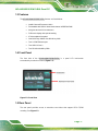
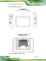
1.4 Front Panel
The front side of the AFL4-W10/W12/12/W13-EHL is a panel LCD touchscreen
surrounded by an aluminum frame (Figure 1-2).
Figure 1-2: Front View
1.5 Rear Panel
The rear panel provides access to retention screw holes that support VESA 75/100
mounting. See Figure 1-3.

AFL4-W10/W12/12/W13-EHL Panel PC
Page 18
Figure 1-3: Rear View
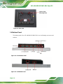
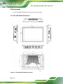
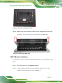
1.6 Bottom Panel
The bottom panel of the AFL4-W10/W12/12/W13-EHL has the following connectors and
switches.
Figure 1-4: Front Bottom Panel
Figure 1-5: Left Bottom Panel

AFL4-W10/W12/12/W13-EHL Panel PC
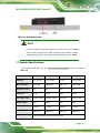
Page 19
Figure 1-6: Right Bottom Panel
NOTE:
Before installing the operating system, the user must enter the Boot
BIOS menu first and choose which operating system will be installed.
Otherwise the USB 3.2 Gen 2 ports cannot be used for OS installation.
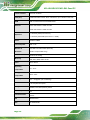
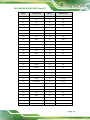
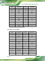
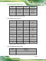
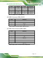
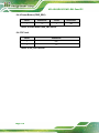
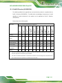
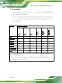
1.7 System Specifications
The technical specifications for the AFL4-W10/W12/12/W13-EHL systems are listed in
Table 1-2.
Specification
AFL4-W10-EHL
AFL4-W12-EHL
AFL4-12-EHL
AFL4-W13-EHL
LCD Size
10.1" (16:10)
12.1" (16:10)
12” (4:3)
13.3" (16:10)
Max. Resolution
1280 x 800
1280 x 800
1024 x 768
1920 x1080
Brightness (cd/m2)
350
500
500
350
LCD Color
16.7M
16.7M
16.7M
16.7M
Pixel Pitch (mm)
0.1695 x 0.1695
0.1695 x 0.1695
0.24 x 0.24
0.153 x 0.153
Contrast Ratio
900:1
1200:1
700:1
800:1
Viewing Angle (H-V)
170°/170°
170°/170°
160°/140°
170°/170°
Backlight MTBF
30000 hours
50000 hours
50000 hours
50000 hours
Touchscreen
PCAP with USB interface (anti-UV/AG coating)

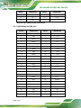
AFL4-W10/W12/12/W13-EHL Panel PC
Page 20
Touch Controller
EETI EXC 81 Series
CPU (SoC)
Intel® Celeron® Processor J6412 1.5M Cache, up to 2.60 GHz / TDP 10W
RAM
8GB on-board dual-channel LPDDR4x RAM
Ethernet
LAN1: Intel ® I225V 2.5GbE controller
LAN2: Intel ® I225V 2.5GbE controller
Expansion
1 x M.2 M key 2242 (PCIe Gen3 x1)
1 x M.2 M key 2242/2280 (PCIe Gen3 x1 + SATA)
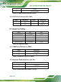
Audio
Realtek ALC888S
Internal Speaker
AMP 1.2 W
Wireless &
Bluetooth
IEEE 802.11ax 2T2R module (Wi-Fi 6E)
with BT v5.2 (M.2 2230 A-key)
Construction
Aluminum die casting
Mounting
Wall, Stand, ARM, VESA 75/100
Color
Silver + Black
Operating
Temperature
-10 ~ 50 ºC
Storage
Temperature
-20ºC ~ 60ºC
Humidity
10% ~ 95%@40ºC (non-condensing)
IP Level
IP 64 compliant front panel
Safety/EMC
CE/EMC, FCC, RED (Class A), UKCA
Power Requirement
12V
Thermal Solution
Fanless
OS
Windows/Linux
ErP
ErP 2009/125/EC
La pagina sta caricando ...
La pagina sta caricando ...
La pagina sta caricando ...
La pagina sta caricando ...
La pagina sta caricando ...
La pagina sta caricando ...
La pagina sta caricando ...
La pagina sta caricando ...
La pagina sta caricando ...
La pagina sta caricando ...
La pagina sta caricando ...
La pagina sta caricando ...
La pagina sta caricando ...
La pagina sta caricando ...
La pagina sta caricando ...
La pagina sta caricando ...
La pagina sta caricando ...
La pagina sta caricando ...
La pagina sta caricando ...
La pagina sta caricando ...
La pagina sta caricando ...
La pagina sta caricando ...
La pagina sta caricando ...
La pagina sta caricando ...
La pagina sta caricando ...
La pagina sta caricando ...
La pagina sta caricando ...
La pagina sta caricando ...
La pagina sta caricando ...
La pagina sta caricando ...
La pagina sta caricando ...
La pagina sta caricando ...
La pagina sta caricando ...
La pagina sta caricando ...
La pagina sta caricando ...
La pagina sta caricando ...
La pagina sta caricando ...
La pagina sta caricando ...
La pagina sta caricando ...
La pagina sta caricando ...
La pagina sta caricando ...
La pagina sta caricando ...
La pagina sta caricando ...
La pagina sta caricando ...
La pagina sta caricando ...
La pagina sta caricando ...
La pagina sta caricando ...
La pagina sta caricando ...
La pagina sta caricando ...
La pagina sta caricando ...
La pagina sta caricando ...
La pagina sta caricando ...
La pagina sta caricando ...
La pagina sta caricando ...
La pagina sta caricando ...
La pagina sta caricando ...
La pagina sta caricando ...
La pagina sta caricando ...
La pagina sta caricando ...
La pagina sta caricando ...
La pagina sta caricando ...
La pagina sta caricando ...
La pagina sta caricando ...
La pagina sta caricando ...
La pagina sta caricando ...
La pagina sta caricando ...
La pagina sta caricando ...
La pagina sta caricando ...
La pagina sta caricando ...
La pagina sta caricando ...
La pagina sta caricando ...
La pagina sta caricando ...
La pagina sta caricando ...
La pagina sta caricando ...
La pagina sta caricando ...
La pagina sta caricando ...
La pagina sta caricando ...
La pagina sta caricando ...
La pagina sta caricando ...
La pagina sta caricando ...
La pagina sta caricando ...
La pagina sta caricando ...
La pagina sta caricando ...
La pagina sta caricando ...
La pagina sta caricando ...
La pagina sta caricando ...
La pagina sta caricando ...
La pagina sta caricando ...
La pagina sta caricando ...
La pagina sta caricando ...
La pagina sta caricando ...
La pagina sta caricando ...
La pagina sta caricando ...
La pagina sta caricando ...
La pagina sta caricando ...
La pagina sta caricando ...
La pagina sta caricando ...
La pagina sta caricando ...
La pagina sta caricando ...
La pagina sta caricando ...
La pagina sta caricando ...
La pagina sta caricando ...
La pagina sta caricando ...
La pagina sta caricando ...
La pagina sta caricando ...
La pagina sta caricando ...
La pagina sta caricando ...
La pagina sta caricando ...
La pagina sta caricando ...
La pagina sta caricando ...
La pagina sta caricando ...
La pagina sta caricando ...
La pagina sta caricando ...
La pagina sta caricando ...
-
 1
1
-
 2
2
-
 3
3
-
 4
4
-
 5
5
-
 6
6
-
 7
7
-
 8
8
-
 9
9
-
 10
10
-
 11
11
-
 12
12
-
 13
13
-
 14
14
-
 15
15
-
 16
16
-
 17
17
-
 18
18
-
 19
19
-
 20
20
-
 21
21
-
 22
22
-
 23
23
-
 24
24
-
 25
25
-
 26
26
-
 27
27
-
 28
28
-
 29
29
-
 30
30
-
 31
31
-
 32
32
-
 33
33
-
 34
34
-
 35
35
-
 36
36
-
 37
37
-
 38
38
-
 39
39
-
 40
40
-
 41
41
-
 42
42
-
 43
43
-
 44
44
-
 45
45
-
 46
46
-
 47
47
-
 48
48
-
 49
49
-
 50
50
-
 51
51
-
 52
52
-
 53
53
-
 54
54
-
 55
55
-
 56
56
-
 57
57
-
 58
58
-
 59
59
-
 60
60
-
 61
61
-
 62
62
-
 63
63
-
 64
64
-
 65
65
-
 66
66
-
 67
67
-
 68
68
-
 69
69
-
 70
70
-
 71
71
-
 72
72
-
 73
73
-
 74
74
-
 75
75
-
 76
76
-
 77
77
-
 78
78
-
 79
79
-
 80
80
-
 81
81
-
 82
82
-
 83
83
-
 84
84
-
 85
85
-
 86
86
-
 87
87
-
 88
88
-
 89
89
-
 90
90
-
 91
91
-
 92
92
-
 93
93
-
 94
94
-
 95
95
-
 96
96
-
 97
97
-
 98
98
-
 99
99
-
 100
100
-
 101
101
-
 102
102
-
 103
103
-
 104
104
-
 105
105
-
 106
106
-
 107
107
-
 108
108
-
 109
109
-
 110
110
-
 111
111
-
 112
112
-
 113
113
-
 114
114
-
 115
115
-
 116
116
-
 117
117
-
 118
118
-
 119
119
-
 120
120
-
 121
121
-
 122
122
-
 123
123
-
 124
124
-
 125
125
-
 126
126
-
 127
127
-
 128
128
-
 129
129
-
 130
130
-
 131
131
-
 132
132
-
 133
133
-
 134
134


IEI Integration AFL4-W13-EHL Manuale utente
- Categoria
- Schede madri
- Tipo
- Manuale utente
- Questo manuale è adatto anche per