
O P E R A T I N G I N S T R U C T I O N
GSE6L
Miniature photoelectric sensors


Described product
G6L
GSE6L
Manufacturer
SIC
K AG
Er
win-Sick-Str. 1
79183 Waldkirch
Germany
Production location
SICK Malay
sia
Legal information
This work is protected by copyright. Any rights derived from the copyright shall be
reserved for SICK AG. Reproduction of this document or parts of this document is only
permissible within the limits of the legal determination of Copyright Law. Any modifica‐
tion, abridgment or translation of this document is prohibited without the express writ‐
ten permission of SICK AG.
The trademarks stated in this document are the property of their respective owner.
© SICK AG. All rights reserved.
Original document
T
his document is an or
iginal document of SICK AG.
Laser
1
2006/42/EC
NO
SAFETY
8025390 / 24.06.2020 | SICK
Subject to change without notice
3

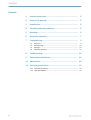
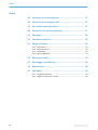
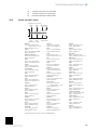
Contents
1 General safety notes......................................................................... 5
2 Notes on UL approval........................................................................ 5
3 Intended use...................................................................................... 5
4 Operating and status indicators...................................................... 5
5 Mounting............................................................................................. 6
6 Electrical installation........................................................................ 7
7 Commissioning.................................................................................. 9
7.1 Alignment.................................................................................................. 9
7.2 Sensing range........................................................................................... 10
7.3 Settings..................................................................................................... 10
7.4 Additional functions.................................................................................. 11
8 Troubleshooting................................................................................. 11
9 Disassembly and disposal............................................................... 12
10 Maintenance...................................................................................... 12
11 Technical specifications................................................................... 13
11.1 Dimensional drawing................................................................................ 13
11.2 Light spot diagram.................................................................................... 14
CONTENTS
4
8025390 / 24.06.2020 | SICK
Subject to change without notice

1 General safety notes
■
Read t
he operating instructions before commissioning.
■
Connection, mounting, and configuration may only be performed by trained
specialist
s.
■
2006/42/EC
NO
SAFETY
Not a safety component in accordance with the EU Machinery Directive.
■
When commissioning, protect the device from moisture and contamination.
■
These oper
ating instructions contain information required during the life cycle of
the sensor.
EN/IEC 60825-1:2014
IEC60825-1:2007
Laser
1
Maximum pulse power 1.67 mW
Puls length: 7 µs
Wavelength: 670 - 690 nm
Complies with FDA performance
standards except for conformance
with IEC 60825-1 Ed. 3, as
described in Laser Notice No. 56,
dated May 8, 2019
LASER CLASS 1
ATTENTION
WARNING: Interruption, manipulation or incorrect use can lead to hazardous exposure
due to laser radiation.
2 Notes on UL approval
UL Environmental Rating: Enclosure type 1
3 Intended use
The GSE6L is an opto-electronic through-beam photoelectric sensor (referred to as
“sensor” in the f
ollowing) for the optical, non-contact detection of objects. A sender
(GS) and a receiver (GE) are required for operation. If the product is used for any other
purpose or modified in any way, any warranty claim against SICK AG shall become void.
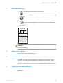
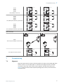
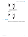
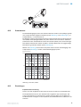
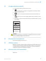
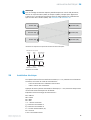
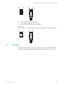
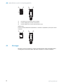
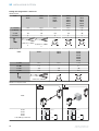
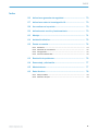
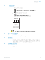
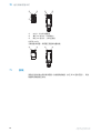
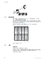
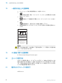
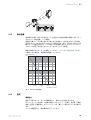
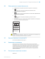
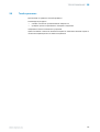
4 Operating and status indicators
GSE6L-xxx1x
GENERAL SAFETY NOTES 1
8025390 / 24.06.2020 | SICK
Subject to change without notice
5

1
2 3
23
1
1
Potentiometer: sensitivity adjustment
2
Yellow LED indicator: Switching output
3
LED indicator green: supply voltage active
GSE6L-xxx3x
Sensor whic
h it is no
t pos
sible to set: The sensor is adjusted and ready for operation.
2 3
23
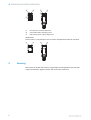
5 Mounting
Mount sensors (sender and receiver) using suitable mounting brackets (see the SICK
rang
e of accessories). Align the sender and receiver with each other.
4 OPERATING AND STATUS INDICATORS
6
8025390 / 24.06.2020 | SICK
Subject to change without notice

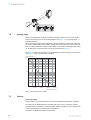
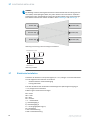
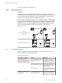
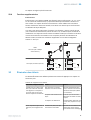
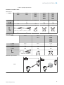
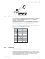
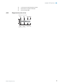
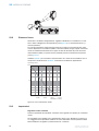
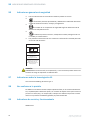
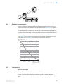
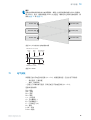
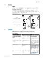
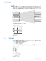
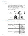
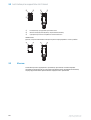
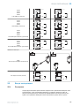
NOTE
When mountin
g through beam photoelectric sensors adjacent to each other, alternate
the sender (GS6L) and receiver (GE6L) arrangement every other pair. Also ensure that
there is sufficient distance between pairs based on the sender (GS6L) light spot diame‐
ter. Refer to figure 1 and figure 2.
Receiver (GE)
Receiver (GE)
Sender (GS)
Sender (GS)
Sender (GS)
Receiver (GE)
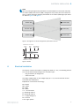
Figure 1: Arrangement of several through-beam photoelectric sensors
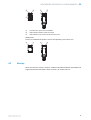
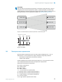
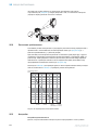
Sensor
Ø 70
(2.76)
Ø 3.5
(0.14)
Ø 90
(3.54)
Ø 120
(4.72)
Distance in m (feet)
Diameter in mm (inch)
1
(3.28)
12
(39.37)
30
(98.43)
40
(131.23)
Figure 2: GSE6L
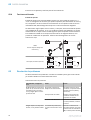
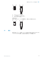
6 Electrical installation
The sensors must be connected in a voltage-free state (U
V
= 0 V). The following informa‐
tion must be observed depending on the connection type:
– Plug connection: pin assignment
– Cable: wire color
Only apply voltage/switch on the voltage supply (U
V
> 0 V) once all electrical connec‐
tions have been established.
Explanation of connection terminology:
BN = Brown
WH = White
BU = Blue
BK = Black
n. c. = no connection
Q = switching output 1
Q = switching output 2
L+ = supply voltage (Uv)
M = common
L.ON = light operate
ELECTRICAL INSTALLATION 6
8025390 / 24.06.2020 | SICK
Subject to change without notice
7

D.ON = dark operate
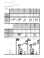
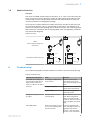
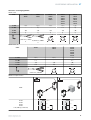
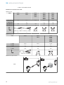
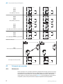
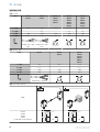
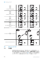
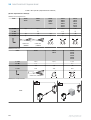
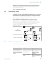
Connection and Output detail:
Table 1: DC
GE6L -P1xxx
-N1xxx
-E2xxx
-F2xxx
-P3xxx
-N3xxx
-P5xxx
-N5xxx
-P4xxx
-N4xxx
-P6xxx
-N6xxx
-P7xxx
-N7xxx
-E4xxx
-F4xxx
-E6xxx
-F6xxx
-E7xxx
-F7xxx
1 = BN + (L+) + (L+) + (L+) + (L+) + (L+)
2 = WH -
Q
- n. c.
Q
3 = BU - (M) - (M) - (M) - (M) - (M)
4 = BK Q Q Q Q Q
0.205 mm
2
/
AWG24
0.205 mm
2
/
AWG24
1
4
3
2
1
4
3
2
1
4
3
Table 2: DC, GS
GS6L- -D1xxx -D3xxx
-D5xxx
-D4xxx
-D6xxx
-D7xxx
-D
Axxx
-DBxxx
-DCxxx
1 = BN + (L+) + (L+) + (L+)
2 = WH n. c. - n. c.
3 = BU - (M) - (M) - (M)
4 = BK T
est Test Test
0.205 mm
2
/ A
W
G24
1
4
3
2
1
4
3
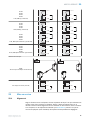
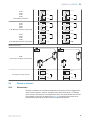
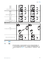
Table 3: Output function
GE6L
-Px1xx
-Px2xx
-Px5xx
-Px6xx
L.ON
, PNP: Q (≤
100 mA)
+ (L+)
Q
‒ (M)
Load
+ (L+)
Q
‒ (M)
Load
6 ELECTRICAL INSTALLATION
8
8025390 / 24.06.2020 | SICK
Subject to change without notice

-Px1xx
-Px2xx
-Px3xx
-Px4xx
D.ON
, PNP: Q (
≤ 100 mA)
+ (L+)
Q
‒ (M)
Load
+ (L+)
Q
‒ (M)
Load
-Nx1xx
-Nx2xx
-Nx5xx
-Nx6xx
L.ON
, NP
N Open C
ollector Q (≤ 100 mA)
+ (L+)
Q
! (M)
+ (L+)
Q
! (M)
Load
+ (L+)
Q
! (M)
Load
-Nx1xx
-Nx2xx
-Nx3xx
-Nx4xx
D.ON
, NPN Open C
ollector Q (≤ 100 mA)
+ (L+)
Q
! (M)
Load
+ (L+)
Q
! (M)
+ (L+)
Q
! (M)
Load
Table 4: Test input
GS6L
T
he te
st input is always connected to Q
Test input, low active (≤ 2 mA)
+ (L+)
Test
– (M)
+ (L+)
T
es
t
– (M)
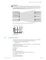
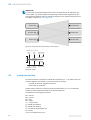
7 Commissioning
7.1 Alignment
Align the sender with the receiver. Select the position so that the red emitted light beam
hit
s t
he r
eceiver. Tip: Use white paper or a reflector as an alignment aid. The sender
must have a clear view of the receiver, with no object in the path of the beam [see
figure 0]. You must ensure that the optical openings (front screen) of the sensors are
completely clear.
COMMISSIONING 7
8025390 / 24.06.2020 | SICK
Subject to change without notice
9

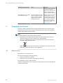
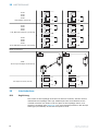
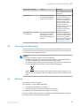
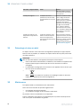
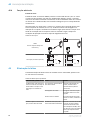
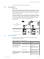
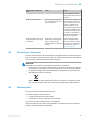
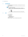
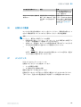
7.2 Sensing range
Observe the application conditions: Adjust the distance between the sender and the
recei
ver according to the corresponding diagram [see figure 3] (x = sensing range, y =
operating reserve).
When mounting through beam photoelectric sensors adjacent to each other, alternate
the sender (GS6L) and receiver (GE6L) arrangement every other pair. Also ensure that
there is sufficient distance between pairs based on the sender (GS6L) light spot diame‐
ter. By doing this, mutual interference can be prevented [see figure 1].
Use table 3 to check the function. If the switching output fails to behave in accordance
wit
h table 3, check the application conditions.
100
10
1
Operating reserve
40
(131.23)
10
(32.80)
20
(65.62)
30
(98.43)
0
Distance in m (feet)
Figure 3: Characteristic curve, GSE6L
7.3 Settings
Sensitivity setting
Sensor whic
h it is not pos
sible to set: The sensor is adjusted and ready for operation.
The sensitivity is adjusted with the potentiometer (type: 5-turn). Clockwise rotation:
operating reserve increased; counterclockwise rotation: operating reserve reduced. We
recommend setting the potentiometer to “Maximum”.
The sensor is adjusted and ready for operation.
7 C
OMMISSIONING
10
8025390 / 24.06.2020 | SICK
Subject to change without notice

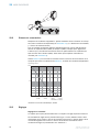
7.4 Additional functions
Test input
T
es
t input: The GSE6L sensors feature a test input (“TI” or “Test” on the connection dia‐
gram), which can be used to switch the sender off and therefore check that the sensor
is functioning correctly: If female cable connectors with LED indicators are used, you
must ensure that the TI is assigned accordingly.
There must be no object between the sender and receiver; activate the test input (see
the connection diagram, TI at 0 V). The send LED is shut down or the detection of an
object is simulated. Use the following table to check the function. If the switching output
fails to behave in accordance with the following table, check the application conditions.
See section Fault diagnosis.
Table 5: Test input
GS6L
T
he te
st input is always con‐
nected to Q
Test input, low active (≤ 2 mA)
+ (L+)
Test
– (M)
+ (L+)
T
es
t
– (M)
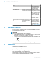
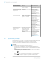
8 Troubleshooting
The Troubleshooting table indicates measures to be taken if the sensor stops working.
Table 6: Troubleshooting
LED indicator/fault pattern Cause Measures
Yellow LED does not light up
even t
hough the light beam is
aligned to the receiver and
there is no object in the path of
the beam
No voltage or voltage below
the limit values
Check the power supply,
check all electrical connec‐
tions (cables and plug connec‐
tions)
Voltage interruptions Ensure there is a stable power
supply without interruptions
Sensor is faulty If the power supply is OK,
replace the sensor
N
o object in beam path, no out‐
put signal
Test input (Test) is not con‐
nected properly
Check connection of the test
input. When using female
cable connectors with LED
indicators, make sure the test
input is assigned correspond‐
ingly.
Yellow LED flashes Sensor is still ready for opera‐
tion, but the oper
ating condi‐
tions are not ideal
Check the operating condi‐
tions: Fully align the beam of
light (light spot) with the
receiver. / Clean the optical
surfaces / If the potentiome‐
COMMISSIONING 7
8025390 / 24.06.2020 | SICK
Subject to change without notice
11

LED indicator/fault pattern Cause Measures
ter is set to the max. sensitiv‐
ity: R
educe the distance
between the sender and the
receiver / Check sensing
range and adjust if necessary
Yellow LED lights up, no object
in the pat
h of the beam
The beam of light of a photo‐
electric through-beam sensor
hits the receiver of another
(neighboring) photoelectric
through-beam sensor
Swap the sender and receiver
arrangement at every sec‐
ond through-beam photoelec‐
tric sensor and ensure that
there is sufficient distance
between the through-beam
photoelectric sensors : see
figure 1, page 7
9 Disassembly and disposal
The sensor must be disposed of according to the applicable country-specific regula‐
tions. Ef
forts should be made during the disposal process to recycle the constituent
materials (particularly precious metals).
NOTE
Disposal of ba
tteries, electric and electronic devices
•
According to international directives, batteries, accumulators and electrical or
electronic devices must not be disposed of in general waste.
•
The owner is obliged by law to return this devices at the end of their life to the
respective public collection points.
•
WEEE:
This symbol on the product, its package or in this document, indi‐
cat
es that a product is subject to these regulations.
10 Maintenance
SICK sensors are maintenance-free.
We recommend doing the following regularly:
•
Clean the external lens surfaces
•
Check the screw connections and plug-in connections
No modifications may be made to devices.
Subject to change without notice. Specified product properties and technical data are
not written guarantees.
9 DISASSEMBLY AND DISPOSAL
12
8025390 / 24.06.2020 | SICK
Subject to change without notice

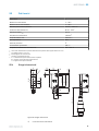
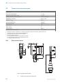
11 Technical specifications
Laser class 1
Sensing range 1 ... 30 m
Sensing range max. 1 ... 40 m
Light spot diameter/distance 3.5 mm / 1000 mm
Supply voltage U
B
DC 10 ... 30 V
1)
Output current I
max.
30 mA
S
witching frequency 1,000 Hz
2)
Max. response time 0.625 ms
3)
Enclosure rating IP67
Protection class II
4)
Circuit protection A, B, C
5)
Ambient operating temperature -20 ... +50 °C
1)
Limit values. U
B
connect
ions reverse-polarity protected. Residual ripple max 5 V
PP
2)
With light / dark ratio 1:1
3)
Signal transit time with resistive load
4)
Reference voltage DC 50 V
5)
A = U
B
-connections reverse polarity protected
B = input
s and output reverse-polarity protected
C = Interference suppression
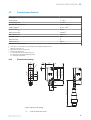
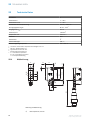
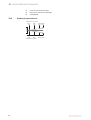
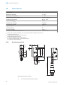
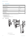
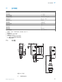
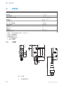
11.1 Dimensional drawing
6.3
(0.25)
0.5
(0.02)
21
(0.83)
0.5
(0.02)
9.7
(0.38)
3
(0.12)
11.5
(0.45)
31.5 (1.24)
28.5 (1.12)
25.4 (1.00)
2.3
(0.09)
18.3
(0.72)
305 (12.01)
9.7
(0.38)
12
(0.47)
1
2
4
4
3
Figure 4: Dimensional drawing
1
Center of optical axis, sender
TECHNICAL SPECIFICATIONS 11
8025390 / 24.06.2020 | SICK
Subject to change without notice
13

2
Center of optical axis, receiver
3
Operating and status indicators
4
M3 threaded mounting hole
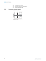
11.2 Light spot diagram
Sensor
Ø 70
(2.76)
Ø 3.5
(0.14)
Ø 90
(3.54)
Ø 120
(4.72)
Distance in m (feet)
Diameter in mm (inch)
1
(3.28)
12
(39.37)
30
(98.43)
40
(131.23)
11 TECHNICAL SPECIFICATIONS
14
8025390 / 24.06.2020 | SICK
Subject to change without notice


Beschriebenes Produkt
G6L
GSE6L
Hersteller
SIC
K AG
Er
win-Sick-Str. 1
79183 Waldkirch
Deutschland
Fertigungsstandort
SICK Malay
sia
Rechtliche Hinweise
Dieses Werk ist urheberrechtlich geschützt. Die dadurch begründeten Rechte bleiben
bei der Firma SICK AG. Die Vervielfältigung des Werks oder von Teilen dieses Werks ist
nur in den Grenzen der gesetzlichen Bestimmungen des Urheberrechtsgesetzes zuläs‐
sig. Jede Änderung, Kürzung oder Übersetzung des Werks ohne ausdrückliche schriftli‐
che Zustimmung der Firma SICK AG ist untersagt.
Die in diesem Dokument genannten Marken sind Eigentum ihrer jeweiligen Inhaber.
© SICK AG. Alle Rechte vorbehalten.
Originaldokument
Die
ses D
okument ist ein Originaldokument der SICK AG.
Laser
1
2006/42/EC
NO
SAFETY
16
8025390 / 24.06.2020 | SICK
Subject to change without notice

Inhalt
12 Allgemeine Sicherheitshinweise..................................................... 18
13 Hinweise zur UL Zulassung.............................................................. 18
14 Bestimmungsgemäße Verwendung............................................... 18
15 Betriebs- und Statusanzeigen.......................................................... 18
16 Montage.............................................................................................. 19
17 Elektrische Installation..................................................................... 20
18 Inbetriebnahme................................................................................. 22
18.1 Angleichung............................................................................................... 22
18.2 Schaltabstand........................................................................................... 23
18.3 Einstellungen............................................................................................. 23
18.4 Weitere Funktionen.................................................................................. 24
19 Störungsbehebung............................................................................ 24
20 Demontage und Entsorgung............................................................ 25
21 Wartung.............................................................................................. 25
22 Technische Daten.............................................................................. 26
22.1 Maßzeichnung........................................................................................... 26
22.2 Lichtfleckdiagramm.................................................................................. 27
INHALT
8025390 / 24.06.2020 | SICK
Subject to change without notice
17

12 Allgemeine Sicherheitshinweise
■
Lesen S
ie vor der Inbetriebnahme des Geräts die Betriebsanleitung.
■
Der Anschluss, die Montage und die Konfiguration des Geräts dürfen nur
von ge
schultem Fachpersonal vorgenommen werden.
■
2006/42/EC
NO
SAFETY
Bei diesem Gerät handelt es sich um kein sicherheitsgerichtetes Bauteil im
S
inne der EU-Ma
sc
hinenrichtlinie.
■
Bei der Inbetriebnahme ist das Gerät ausreichend vor Feuchtigkeit und Ver‐
schmutz
ung zu schützen.
■
Die vorliegende Betriebsanleitung enthält Informationen, die während des Lebens‐
zyklus der Lichtschranke benötigt werden.
EN/IEC 60825-1:2014
IE
C60825-1:2007
Laser
1
Maximale Pulsleistung: 1,67 mW
Impulsdauer: 7 µs
Wellenlänge: 670 - 690 nm
Entspricht den FDA
Leistungsstandards mit Ausnahme der
Konformität mit IEC 60825-1, Ed. 3
wie im Laserhinweis Nr. 56 vom
08.05.2019 beschrieben
LASERKLASSE 1
ACHTUNG
WARNUN
G: Eingriffe, Manipulation oder eine unsachgemäße Verwendung können zu
gefährlicher Exposition gegenüber Laserstrahlung führen.
13 Hinweise zur UL Zulassung
UL Environmental Rating: Enclosure type 1
14 Bestimmungsgemäße Verwendung
Die GSE6L ist eine optoelektronische Einweg-Lichtschranke (im Folgenden Sensor
genannt) und wir
d zum optischen, berührungslosen Erfassen von Sachen eingesetzt.
Zum Betrieb ist ein Sender (GS) und ein Empfänger (GE) erforderlich. Bei jeder anderen
Verwendung und bei Veränderungen am Produkt verfällt jeglicher Gewährleistungsan‐
spruch gegenüber der SICK AG.
15 Betriebs- und Statusanzeigen
GSE6L-xxx1x
12 ALLGEMEINE SICHERHEITSHINWEISE
18
8025390 / 24.06.2020 | SICK
Subject to change without notice

1
2 3
23
1
1
Potentiometer: Einstellung der Empfindlichkeit
2
Anzeige-LED gelb: Schaltausgang
3
Anzeige-LED grün: Versorgungsspannung aktiv
GSE6L-xxx3x
Sensor ohne E
ins
t
ellmöglichkeit: Sensor ist eingestellt und betriebsbereit.
2 3
23
16 Montage
Lichtschranken (Sender und Empfänger) unter Verwendung geeigneter Befestigungs‐
winke
l montieren (siehe SICK-Zubehörpalette). Sender und Empfänger aneinander aus‐
richten.
BETRIEBS- UND STATUSANZEIGEN 15
8025390 / 24.06.2020 | SICK
Subject to change without notice
19

HINWEIS
Bei Montag
e mehrerer Einweg-Lichtschranken nebeneinander die Anordnung des Sen‐
ders (GS6L) und Empfängers (GE6L) bei jedem zweiten Paar vertauschen. Außerdem
basierend auf dem Lichtfleckdurchmesser des Senders (GS6L) einen ausreichend gro‐
ßen Abstand zwischen den Paaren einhalten. Siehe Abbildung 5 und Abbildung 6.
Receiver (GE)
Receiver (GE)
Sender (GS)
Sender (GS)
Sender (GS)
Receiver (GE)
Abbildung 5: Anordnung mehrerer Einweg-Lichtschranken
Sensor
Ø 70Ø 3,5 Ø 90 Ø 120
Abstand in m
Durchmesser in mm
1 12 30 40
Abbildung 6: GSE6L
17 Elektrische Installation
Anschluss der Sensoren muss spannungsfrei (U
V
= 0 V) erfolgen. Je nach Anschlussart
sind die folgenden Informationen zu beachten:
– Steckeranschluss: Anschlussbelegung
– Leitung: Aderfarbe
Erst nach Anschluss aller elektrischen Verbindungen die Spannungsversorgung (U
V
> 0 V) anlegen bzw. einschalten.
Erläuterung der Anschlussterminologie:
BN = braun
WH = weiß
BU = blau
BK = schwarz
n. c. = unbeschaltet
Q = Schaltausgang 1
Q = Schaltausgang 2
L+ = Versorgungsspannung (Uv)
M = gemeinsam
L.ON = Hellauswertung
D.ON = Dunkelauswertung
17 ELEK
TRISCHE INSTALLATION
20
8025390 / 24.06.2020 | SICK
Subject to change without notice
La pagina sta caricando ...
La pagina sta caricando ...
La pagina sta caricando ...
La pagina sta caricando ...
La pagina sta caricando ...
La pagina sta caricando ...
La pagina sta caricando ...
La pagina sta caricando ...
La pagina sta caricando ...
La pagina sta caricando ...
La pagina sta caricando ...
La pagina sta caricando ...
La pagina sta caricando ...
La pagina sta caricando ...
La pagina sta caricando ...
La pagina sta caricando ...
La pagina sta caricando ...
La pagina sta caricando ...
La pagina sta caricando ...
La pagina sta caricando ...
La pagina sta caricando ...
La pagina sta caricando ...
La pagina sta caricando ...
La pagina sta caricando ...
La pagina sta caricando ...
La pagina sta caricando ...
La pagina sta caricando ...
La pagina sta caricando ...
La pagina sta caricando ...
La pagina sta caricando ...
La pagina sta caricando ...
La pagina sta caricando ...
La pagina sta caricando ...
La pagina sta caricando ...
La pagina sta caricando ...
La pagina sta caricando ...
La pagina sta caricando ...
La pagina sta caricando ...
La pagina sta caricando ...
La pagina sta caricando ...
La pagina sta caricando ...
La pagina sta caricando ...
La pagina sta caricando ...
La pagina sta caricando ...
La pagina sta caricando ...
La pagina sta caricando ...
La pagina sta caricando ...
La pagina sta caricando ...
La pagina sta caricando ...
La pagina sta caricando ...
La pagina sta caricando ...
La pagina sta caricando ...
La pagina sta caricando ...
La pagina sta caricando ...
La pagina sta caricando ...
La pagina sta caricando ...
La pagina sta caricando ...
La pagina sta caricando ...
La pagina sta caricando ...
La pagina sta caricando ...
La pagina sta caricando ...
La pagina sta caricando ...
La pagina sta caricando ...
La pagina sta caricando ...
La pagina sta caricando ...
La pagina sta caricando ...
La pagina sta caricando ...
La pagina sta caricando ...
La pagina sta caricando ...
La pagina sta caricando ...
La pagina sta caricando ...
La pagina sta caricando ...
La pagina sta caricando ...
La pagina sta caricando ...
La pagina sta caricando ...
La pagina sta caricando ...
La pagina sta caricando ...
La pagina sta caricando ...
La pagina sta caricando ...
La pagina sta caricando ...
La pagina sta caricando ...
La pagina sta caricando ...
La pagina sta caricando ...
La pagina sta caricando ...
La pagina sta caricando ...
La pagina sta caricando ...
La pagina sta caricando ...
La pagina sta caricando ...
La pagina sta caricando ...
La pagina sta caricando ...
La pagina sta caricando ...
La pagina sta caricando ...
La pagina sta caricando ...
La pagina sta caricando ...
La pagina sta caricando ...
La pagina sta caricando ...
La pagina sta caricando ...
La pagina sta caricando ...
La pagina sta caricando ...
-
 1
1
-
 2
2
-
 3
3
-
 4
4
-
 5
5
-
 6
6
-
 7
7
-
 8
8
-
 9
9
-
 10
10
-
 11
11
-
 12
12
-
 13
13
-
 14
14
-
 15
15
-
 16
16
-
 17
17
-
 18
18
-
 19
19
-
 20
20
-
 21
21
-
 22
22
-
 23
23
-
 24
24
-
 25
25
-
 26
26
-
 27
27
-
 28
28
-
 29
29
-
 30
30
-
 31
31
-
 32
32
-
 33
33
-
 34
34
-
 35
35
-
 36
36
-
 37
37
-
 38
38
-
 39
39
-
 40
40
-
 41
41
-
 42
42
-
 43
43
-
 44
44
-
 45
45
-
 46
46
-
 47
47
-
 48
48
-
 49
49
-
 50
50
-
 51
51
-
 52
52
-
 53
53
-
 54
54
-
 55
55
-
 56
56
-
 57
57
-
 58
58
-
 59
59
-
 60
60
-
 61
61
-
 62
62
-
 63
63
-
 64
64
-
 65
65
-
 66
66
-
 67
67
-
 68
68
-
 69
69
-
 70
70
-
 71
71
-
 72
72
-
 73
73
-
 74
74
-
 75
75
-
 76
76
-
 77
77
-
 78
78
-
 79
79
-
 80
80
-
 81
81
-
 82
82
-
 83
83
-
 84
84
-
 85
85
-
 86
86
-
 87
87
-
 88
88
-
 89
89
-
 90
90
-
 91
91
-
 92
92
-
 93
93
-
 94
94
-
 95
95
-
 96
96
-
 97
97
-
 98
98
-
 99
99
-
 100
100
-
 101
101
-
 102
102
-
 103
103
-
 104
104
-
 105
105
-
 106
106
-
 107
107
-
 108
108
-
 109
109
-
 110
110
-
 111
111
-
 112
112
-
 113
113
-
 114
114
-
 115
115
-
 116
116
-
 117
117
-
 118
118
-
 119
119


in altre lingue
- français: SICK GSE6L Mode d'emploi
- español: SICK GSE6L Instrucciones de operación
- português: SICK GSE6L Instruções de operação
- 日本語: SICK GSE6L 取扱説明書
Documenti correlati
-
SICK GSE6L Istruzioni per l'uso
-
-
SICK GTB6L Istruzioni per l'uso
-
-
-
-
-
-
-