
1/10
Divisione della BETA UTENSILI SPA, Via Volta, 18 - 20845 SOVICO (MB) ITALY Tel. +39.039.20771-Fax + 39.039.2010742
SPECIFICA PRODOTTO
ISTRUZIONI PER L’USO E LA MANUTENZIONE
Informazioni tecniche
Condizioni d’uso previste e limiti operativi
Prescrizioni per gli operatori
Rischi residui
Modalità e frequenza delle ispezioni periodiche d’idoneità
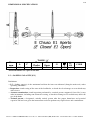
TENDICATENA A CRICCHETTO
ART. 8190
La lingua originale della presente specifica è quella Italiana.
Sede produttiva Accessori per funi ROBUR
Zona Industriale – C.da S. Nicola
67039 SULMONA (L’AQUILA)
Tel. +39.0864.2504.1 – Fax +39.0864.253132
www.beta-tools.com – info@roburitaly.com
R/SP/8190/00
Data 14/04/2020

2/10
Divisione della BETA UTENSILI SPA, Via Volta, 18 - 20845 SOVICO (MB) ITALY Tel. +39.039.20771-Fax + 39.039.2010742
1) CARATTERISTICHE TECNICHE DELL’ACCESSORIO
Materiali:
LEVA Acciaio al carbonio
CORPO Acciaio al carbonio EN 10083-2
ANELLI FILETTATI Acciaio legato da bonifica
ANELLI SALDATI Acciaio legato da bonifica
GANCI Acciaio legato da bonifica
Norme di riferimento:
UNI EN 12195-3
Trattamento Termico:
Normalizzazione leva e corpo, bonifica anelli filettati, anelli saldati,
ganci
Trattamento Superficiale:
Verniciatura epossidica arancio RAL 2004
Il collaudo viene eseguito in base a specifiche e regole interne in riferimento alla norma UNI EN ISO
9001.

3/10
Divisione della BETA UTENSILI SPA, Via Volta, 18 - 20845 SOVICO (MB) ITALY Tel. +39.039.20771-Fax + 39.039.2010742
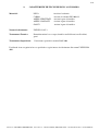
CARATTERISTICHE DIMENSIONALI:
TABELLA “A”
Misura
mm
A C
E
Chiuso
E1
Aperto
G
g
LC
kN
CODICE
10
280 65 365 520 13 5530 63
081900010
Le quote indicate sono espresse in mm.
LC = PORTATA DI ANCORAGGIO [kN]
Definizioni:
• LC: (portata di ancoraggio) è la forza massima che l’articolo può sopportare (lungo l’asse principale)
in condizioni di utilizzo.
• Ispezione: controllo visivo relativo allo stato del tendicatena per individuare evidenti danneggiamenti
o usure che possono alterarne l’utilizzo.
• Esame accurato: esame visivo effettuato da una persona competente e, se necessario, coadiuvato da
altri mezzi, quali i controlli non-distruttivi, al fine di individuare danneggiamenti o usure che possono
alterare l’utilizzo del tendicatena.
• Persona competente: persona designata, istruita correttamente, qualificata per conoscenza ed
esperienza pratica, che ha ricevuto le istruzioni necessarie per eseguire le prove e gli esami richiesti.

4/10
Divisione della BETA UTENSILI SPA, Via Volta, 18 - 20845 SOVICO (MB) ITALY Tel. +39.039.20771-Fax + 39.039.2010742
2) SPECIFICHE DI COLLAUDO
I singoli elementi che compongono l’articolo sono sottoposti a una serie di severi controlli a campione per
accertarne la funzionalità prestazionale e la rispondenza alle specifiche.
La numerosità del campione e i relativi piani di campionamento sono scelti in funzione della caratteristica
da verificare in accordo e per quanto previsto dalla norma UNI ISO 2859/1, e i risultati archiviati
nell’ufficio qualità dello stabilimento di Sulmona.
2.A Controllo dimensionale
Verifica che le dimensioni dell’articolo rientrino nelle tolleranze stabilite dai relativi
disegni di costruzione interni.
2.B Controllo visivo
Verifica la presenza di eventuali imperfezioni dovute a stampaggio, lavorazione
meccanica, rivestimento superficiale e rispondenza della marcatura a disegni di fase
interni.
2.C Analisi chimica
Verifica la rispondenza della composizione chimica del materiale, entro i limiti stabiliti
dalle relative norme.
2.D Analisi metallografica
Verifica il trattamento termico: a 500 ingrandimenti si deve riscontrare la struttura
corrispondente al trattamento termico indicato al punto 1).
2.E Prova del carico di trazione residuo
Il tendicatena, insieme alla catena di ancoraggio con cui è accoppiato, viene caricato ad
un carico pari a 0,3 LC prima di rilasciare il carico di trazione residuo. Il carico da
rilasciare deve essere uguale o minore a 500 N.
2.F Prova di trazione
La prova si esegue in due fasi: la prima consiste nel caricare il tendicatena, insieme alla
catena di ancoraggio con cui è accoppiato, ad un carico pari a 1,25 LC. Il carico viene
mantenuto per un minuto, al termine del quale tutte le parti di sostegno dell’intero sistema
non devono mostrare segni di deformazione o altri difetti che ne compromettono la
funzione. Dopo un’accurata ispezione si applica un carico pari a 2 LC, che deve essere
sostenuto dal sistema senza subire rotture.
2.G Prova di durezza
Verifica che la durezza dell’articolo rientri nei valori stabiliti dai relativi disegni di
costruzione interni.

5/10
Divisione della BETA UTENSILI SPA, Via Volta, 18 - 20845 SOVICO (MB) ITALY Tel. +39.039.20771-Fax + 39.039.2010742
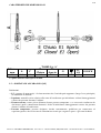
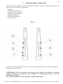
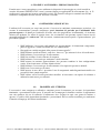
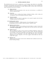
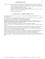
3) COME LEGGERE LA MARCATURA
Sull’accessorio sono stampate in maniera indelebile marcature e sigle che identificano il prodotto e ne
definiscono le caratteristiche e applicazioni.
1) Misura
2) Grado materiale catena
3) Portata di ancoraggio (LC)
4) Non per il sollevamento
5) Marchio produttore
6) Norma di riferimento
7) Codice di lotto
Fig. 1
• Il grado del materiale (dettaglio 2 in fig. 2) si riferisce a quello utilizzato per la catena di ancoraggio da
accoppiare con il tendicatena.
!ATTENZIONE: I dati di marcatura non devono essere rimossi con molature o abrasioni,
(neanche accidentali; i tendicatena senza riferimenti di identificazione devono essere resi
inutilizzabili e rottamati).
Non è consentito apporre caratteri aggiuntivi a quelli di fabbricazione.

6/10
Divisione della BETA UTENSILI SPA, Via Volta, 18 - 20845 SOVICO (MB) ITALY Tel. +39.039.20771-Fax + 39.039.2010742
4) AVVERTENZE GENERALI
Il manuale deve essere custodito da persona responsabile allo scopo preposta, in un luogo idoneo,
affinché esso risulti sempre disponibile per la consultazione nel miglior stato di conservazione. In caso di
smarrimento o deterioramento, la documentazione dovrà essere prontamente sostituita scaricandola dal
sito del costruttore: www.beta-tools.com
Il costruttore si riserva la proprietà materiale ed intellettuale del presente manuale e ne vieta la modifica,
anche parziale, per fini commerciali.
Con riferimento a quanto riportato in queste istruzioni d’uso, la BETA UTENSILI SPA declina ogni
responsabilità in caso di:
• uso degli accessori contrario alle leggi nazionali sulla sicurezza e sull’antinfortunistica;
• errata scelta o predisposizione dell’apparecchio con il quale saranno connessi;
• mancata o errata osservanza delle istruzioni per l’uso;
• modifiche agli accessori;
• uso improprio e omessa manutenzione ordinaria;
• uso combinato ad accessori non conformi.
5) CRITERI DI SCELTA
I parametri che devono essere attentamente considerati nella scelta del tendicatena sono:
5.A PORTATA DI ANCORAGGIO DEL TENDICATENA (LC)
La trazione che il tendicatena deve esercitare deve essere inferiore o uguale al valore della portata di
ancoraggio (LC) previsto per l’articolo preso in considerazione, e riportato nella tabella “A”.
5.B ELEMENTO DI ACCOPPIAMENTO
Assicurarsi che l’elemento di collegamento sia adeguato alle caratteristiche di portata del tendicatena, e
garantisca una resistenza meccanica sufficiente alla trazione esercitata dalla presa.
5.C TEMPERATURE D’IMPIEGO
L’intervallo di temperatura in cui è consentito l’impiego dell’accessorio va da 0°C a +200°C.
5.D VITA E FREQUENZA DI UTILIZZO
L’accessorio lavora in perfetta efficienza fin quando restano invariate le sue caratteristiche geometriche e
fisiche.
Sostituire quindi il tendicatena quando si notano riduzioni di sezione, deformazioni, corrosioni o
instabilità di accoppiamento.
6) CONDIZIONI NON AMMESSE
Non è consentito far lavorare i tendicatena nei seguenti casi:
• quando la forza applicata è superiore all’ “LC” consentito;
• nelle condizioni in cui si possono creare delle sollecitazioni di tipo dinamico o carichi
pulsanti;
• far lavorare i tendicatena a temperature diverse da quelle consentite;
• quando la direttrice delle forze non si sviluppa lungo l’asse principale che attraversa i due
terminali.

7/10
Divisione della BETA UTENSILI SPA, Via Volta, 18 - 20845 SOVICO (MB) ITALY Tel. +39.039.20771-Fax + 39.039.2010742
7) CONTROLLI PRELIMINARI
Prima della messa in servizio e/o del montaggio gli accessori devono essere controllati da una persona
competente adeguatamente addestrata.
• Controllare l’integrità del tendicatena e in particolare che non vi siano tagli, piegature,
incisioni, abrasioni, incrinature o cricche, filetti irregolari, corrosioni, bave taglienti,
usure provocate dall’utilizzo o difetti dovuti a cattivo stoccaggio.
• Rilevare e registrare le dimensioni con riferimento alla tabella “A”.
• Controllare l’integrità della marcatura in tutte le sue parti, al fine di identificare con
precisione l’accessorio in funzione della forza di lavoro.
• Verificare la bontà dell’accoppiamento tra i filetti.
8) INSTALLAZIONE - ISTRUZIONI PER IL MONTAGGIO
Durante l’installazione dell’accessorio indossare i dispositivi di protezione adeguati:
guanti, scarpe antinfortunistiche, elmetto, etc.
E’ indispensabile riferirsi alla norma UNI EN 12195-1 per il calcolo del numero dei punti di ancoraggio e
alla UNI EN 12195-3 per l’applicazione del precarico.
Durante il trasporto non è mai consentito superare la portata di ancoraggio LC.
Assicurarsi che la catena di ancoraggio e i relativi punti di collegamento siano adeguati alla portata di
ancoraggio del tendicatena, e garantiscano una resistenza meccanica sufficiente alla trazione esercitata
dalla presa. Tutte queste valutazioni devono essere eseguite da persona competente.
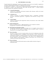
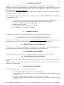
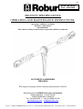
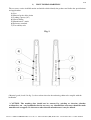
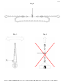
Svitare manualmente i terminali in maniera da ottenere l’apertura massima E1.
Collegare i terminali, tramite i relativi ganci accorciatori, alla catena di ancoraggio (esempio di
montaggio mostrato in fig. 2).
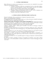
Posizionare il selettore di movimento A in posizione di avvitamento; quindi agire avanti e indietro sulla
leva per applicare tensione alla catena di ancoraggio (fig. 3). E’ proibito l’utilizzo di prolunghe sulla leva
di azionamento.
Particolare attenzione deve essere posta durante il tensionamento affinché non venga superata la portata
di ancoraggio (LC, vedi tabella ”A”), per non incorrere in deformazioni permanenti.
Nell’esercitare la trazione assicurarsi che il tendicatena abbia piena libertà di movimento e di
autoposizionamento; non devono quindi mai presentarsi forzature o interferenze che possano generare
componenti di forza laterali.
La condizione di trazione deve essere controllata dopo breve tempo per compensare eventuali adattamenti
del sistema.
Per allentare la tensione, posizionare il selettore A in posizione di svitamento e agire avanti e indietro
sulla leva (fig. 3). Una volta annullata la tensione è possibile liberare la catena di ancoraggio dai ganci
accorciatori.

8/10
Divisione della BETA UTENSILI SPA, Via Volta, 18 - 20845 SOVICO (MB) ITALY Tel. +39.039.20771-Fax + 39.039.2010742
Fig. 2
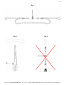
Fig. 3 Fig. 4

9/10
Divisione della BETA UTENSILI SPA, Via Volta, 18 - 20845 SOVICO (MB) ITALY Tel. +39.039.20771-Fax + 39.039.2010742
9) USO DELL’ACCESSORIO - PRESA E MANOVRA
Il tendicatena è stato concepito per essere utilizzato in dispositivi di ancoraggio su veicoli stradali in
accordo alla norma UNI EN 12195-3; non è pertanto idoneo per applicazioni di sollevamento (fig. 4). Il
tendicatena è concepito per lavorare sotto forze assiali. Gli elementi collegati ai terminali non devono
trasmettere componenti di forze laterali, flessione o torsione.
10) CONTROINDICAZIONI D’USO
L’utilizzo dell’accessorio per scopi non previsti, il suo uso in condizioni estremamente pericolose e la
carenza di manutenzione possono comportare gravi situazioni di pericolo per l’incolumità delle
persone esposte e di danno per l’ambiente di lavoro, oltre che pregiudicare la funzionalità e la sicurezza
effettiva del prodotto. Le azioni di seguito citate, che, ovviamente, non possono coprire l’intero arco di
potenziali possibilità di “cattivo uso” dell’accessorio, costituiscono tuttavia quelle “ragionevolmente” più
prevedibili. Quindi:
• NON utilizzare l’accessorio collegandolo ad apparecchiature di dimensioni, temperatura,
punto d’aggancio e forma non idonei alle sue caratteristiche;
• Non applicare carichi maggiori della portata di ancoraggio LC;
• NON utilizzare ausili meccanici, come leve, barre ecc., per azionare la leva del tendicatena;
• NON utilizzare l’accessorio per il sollevamento;
• NON fare oscillare il carico durante il trasporto;
• NON utilizzare l’accessorio per trazionare carichi vincolati;
• NON mettere in tensione apparecchiature che possono cambiare la loro configurazione
statica, il loro baricentro o lo stato chimico-fisico;
• NON utilizzare l’accessorio per il sollevamento o il trasporto di persone o animali;
• NON usare l’accessorio per il traino;
• NON operare in aree dove è prescritto l’uso di componenti antideflagranti/antiscintilla o in
presenza di forti campi magnetici;
• NON saldare sull’accessorio particolari metallici, né intervenire con riporti di saldatura o
utilizzarlo come massa per saldatrici.
11) IDONEITÀ ALL’UTILIZZO
L’accessorio è stato sottoposto a collaudo a campione presso il costruttore per accertare la rispondenza
funzionale e prestazionale dello stesso. L’attestato che accompagna la fornitura certifica il superamento
con esito positivo dei test di collaudo. L’utilizzatore deve eseguire in ogni caso, prima di iniziare a
operare, la verifica della rispondenza funzionale e prestazionale dell’accessorio installato per confermare
l’idoneità all’impiego dell’intera installazione.

10/10
Divisione della BETA UTENSILI SPA, Via Volta, 18 - 20845 SOVICO (MB) ITALY Tel. +39.039.20771-Fax + 39.039.2010742
12) ISPEZIONE E MANUTENZIONE
Comprende una serie di operazioni eseguite da personale competente istruito allo scopo, relative a
controlli ed esami accurati durante l’impiego.
Di seguito l’elenco dei controlli da effettuare con cadenze indicate nella tabella “Interventi di
manutenzione e controllo”.
• VISIVO: verificare l’assenza di difetti superficiali, quali cricche, incisioni, tagli o fessure,
abrasioni.
• CONDIZIONI DEL FILETTO: esaminare lo stato del filetto, che non deve presentare
usure, deformazioni e ammaccature, e l’accoppiamento deve essere preciso, stabile e senza
eccessivo gioco.
• DEFORMAZIONE: verificare che l’accessorio non sia deformato, misurando con un
calibro le dimensioni critiche, come indicato nella tabella “A”. NON sono tollerate
deformazioni rispetto alle quote rilevate alla prima messa in servizio.
• USURA: verificare che i punti di contatto non siano usurati misurando con un calibro le
dimensioni critiche indicate nella tabella “A”.
• STATO DI CONSERVAZIONE: verificare l’assenza di ossidazione e corrosione,
soprattutto in caso di utilizzo all’aperto; verificare l’assenza di cricche con metodi idonei
(es. liquidi penetranti).
Le registrazioni di questi controlli devono essere conservate.
Nel caso in cui il tendicatena sia sottoposto a un utilizzo gravoso, è necessario effettuare le verifiche di
usura e stato di conservazione con maggiore frequenza.
13) DEMOLIZIONE E ROTTAMAZIONE DELL’ACCESSORIO
L’accessorio deve essere demolito mediante taglio, in modo tale che non possa più essere utilizzato, sia al
termine della vita prevista, che nel caso presenti:
- una deformazione permanente rispetto alla misura originale;
- eventuali cricche, distorsioni o e se si riscontrano riduzioni di sezione rispetto alla misura
originale;
- se le condizioni del filetto non garantiscono il perfetto accoppiamento tra le parti, filetti usurati,
deformati, irregolari ecc.
A ogni utilizzo Mese Anno
Controllo visivo gener.
x
Condizioni del filetto
x
Deformazione
x
Usura
x
Stato di conservazione
x
Tabella interventi di manutenzione e controllo
Tipo di controllo

1/10
Division of BETA UTENSILI SPA, Via Volta, 18 - 20845 SOVICO (MB) ITALY Tel. +39.039.20771-Fax + 39.039.2010742
PRODUCT SPECIFICATIONS
OPERATING AND MAINTENANCE INSTRUCTIONS
Techical Specifications
Operating Conditions and Limits
Operator’s Instructions
Residual Risks
How and how often periodical fitness inspections should be conducted
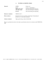
RATCHET LOADBINDER
ITEM 8190
The original language of this technical specification is Italian.
Manufacturing site ROBUR wire ropes accessories
Zona Industriale – C.da S. Nicola
67039 SULMONA (L’AQUILA)
Tel. +39.0864.2504.1 – Fax +39.0864.253132
www.beta-tools.com – info@roburitaly.com
R/SP/8190/00
Date 14/04/2020

2/10
Division of BETA UTENSILI SPA, Via Volta, 18 - 20845 SOVICO (MB) ITALY Tel. +39.039.20771-Fax + 39.039.2010742
1) TECHNICAL SPECIFICATIONS
Material:
LEVER Carbon steel
BODY Carbon steel EN 10083-2
THREADED EYES Steel for hardening and tempering
WELDED LINKS Steel for hardening and tempering
HOOKS Steel for hardening and tempering
Reference standards:
UNI EN 12195-3
Heat treatment:
Normalization for lever and body; hardening and tempering for
threaded eyes, welded links and hooks
Surface treatment:
Epoxy paint Orange coloured RAL 2004
The test is performed on the basis of in-house specifications and rules in accordance with UNI EN ISO
9001.

3/10
Division of BETA UTENSILI SPA, Via Volta, 18 - 20845 SOVICO (MB) ITALY Tel. +39.039.20771-Fax + 39.039.2010742
DIMENSIONAL SPECIFICATIONS:
TABLE “A”
Size
mm
A C
E
Clodes
E1
Open
G
g
LC
kN
CODE
10
280 65 365 520 13 5530 63
081900010
All measurements are expressed in mm.
LC = LASHING CAPACITY [kN]
Definitions:
• LC: (lashing capacity) is the maximum load that the item can withstand (along the main axis) under
operating conditions.
• Inspection: visual testing of the state of the loadbinder, to check for clear damage or wear which may
affect its use.
• Accurate examination: visual inspection performed by a trained person, supported, if need be, by any
other instruments, including non-destructive testing, to check for damage or wear which may affect the
use of the hook.
• Trained person: a designated, suitably trained person who has proper know-how and practical
expertise and has been given the instructions needed to perform any required tests and examinations.

4/10
Division of BETA UTENSILI SPA, Via Volta, 18 - 20845 SOVICO (MB) ITALY Tel. +39.039.20771-Fax + 39.039.2010742
2) TESTING SPECIFICATIONS
The individual parts of the item are subjected to several stringent spot checks for serviceability,
performance and compliance with specifications. The number of samples and the related sampling plans
are chosen according to the characteristic to test under UNI ISO 2859/1, and the results are filed in the
quality department of the factory in Sulmona.
2.A Dimensional test
Making sure that the dimensions of the item meet such tolerances as established in
inhouse working drawings.
2.B Visual test
Testing for defects resulting from forming, mechanical working, surface coating and
correspondence between the marking and in-house drawings.
2.C Chemical analysis
Making sure that the chemical composition of the material complies with the limits
established under the relevant standards.
2.D Metallographic analysis
Testing the heat treatments: at 500 enlargements, the metallographic structure
corresponding to the heat treatment indicated at point 1) should be found.
2.E Residual tensile load test
The loadbinder, together with the anchoring chain with which it is coupled, is loaded with
a load of 0,3 LC before to release the residual tensile load. The load to be released must
be less then or equal to 500 N.
2.F Tensile stress test
The test comprises two phases: the first consists in loading the loadbinder, together with
the anchoring chain with which is coupled at a load of 1,25 LC. The load is maintained
for one minute, at the end of which none of the supporting parts of the system should
show any signs of deformation or any other defects that may affect its operation.
Following an accurate inspection, 2 LC load is applied, which should not cause any
breaks in the system.
2.G Hardness test
Making sure that the hardness of the item lies within the limits established in the relevant
in-house working drawings.

5/10
Division of BETA UTENSILI SPA, Via Volta, 18 - 20845 SOVICO (MB) ITALY Tel. +39.039.20771-Fax + 39.039.2010742
3) HOW TO READ MARKINGS
The accessory carries indelible marks and initials which identify the product and define the specifications
and applications.
1) Size
2) Material grade of the chain
3) Lashing capacity (LC)
4) Not for lifting
5) Manufacturer’s mark
6) Reference standard
7) Traceability code
Fig. 1
• Material grade (detail 2 in fig. 2) refers to that related to the anchoring chain to be coupled with the
loadbinder.
! CAUTION: The marking data should not be removed by grinding or abrasion (whether
accidental or not – any loadbinder that do not carry any identification references should be made
unusable and scrapped). No characters other than the manufacturer’s may be affixed.

6/10
Division of BETA UTENSILI SPA, Via Volta, 18 - 20845 SOVICO (MB) ITALY Tel. +39.039.20771-Fax + 39.039.2010742
4) GENERAL WARNINGS
The manual must be kept by the person in charge in a suitable place and readily available for consultation,
in optimal conditions. should it be lost or damaged, the manual can easily be retrieved on the
manufacturer's web site: www.beta-tools.com The manufacturer detains all material and intellectual rights
on the manual, and restricts its modification, albeit partial, for any commercial use.
As regards the information provided in these operating instructions, BETA UTENSILI S.P.A. will accept
no responsibility in the event of:
• any use of the accessories other than the uses under national safety and accident prevention
laws;
• mistaken choice or arrangement of the lifting apparatus they are going to be connected to;
• failure to comply with, or properly follow, the operating instructions;
• changes to the accessories;
• misuse or failure to carry out routine maintenance jobs;
• use with noncompliant accessories.
5) SELECTION CRITERIA
The following parameters should be carefully considered in choosing the loadbinder:
5.A LASHING CAPACITY OF THE LOADBINDER (LC)
The tensile stress exerted by the loadbinder should be lower than or equal to the lashing capacity (LC)
recommended for the item being considered, and shown in Table “A”.
5.B CONNECTING PART
Make sure that the connecting part suits the lashing capacity of the loadbinder, and ensures an adequate
mechanical resistance to tensile forces exercised by the grip.
5.C OPERATING TEMPERATURES
The permissible operating temperature should be in the range between 0°C and +200°C.
5.D LIFE AND FREQUENCY OF USE
The accessory is perfectly serviceable as long as its geometric and physical characteristics remain
unchanged. Hence the loadbinder should be replaced in case of reduced section, deformation, corrosion or
connecting instability.
6) NONPERMISSIBLE CONDITIONS
The loadbinder should not be operated under the following circumstances:
• when the applied force exceeds the permissible “LC”;
• when dynamic stresses or swinging loads may result;
• when the loadbinder are operated under any temperatures other than the permissible
temperatures;
• when the directrix of forces does not develop along the main axis crossing the two
terminals.

7/10
Division of BETA UTENSILI SPA, Via Volta, 18 - 20845 SOVICO (MB) ITALY Tel. +39.039.20771-Fax + 39.039.2010742
7) PRELIMINARY TESTS
Before the accessories are operated and/or assembled, they should be tested by a suitably trained person.
• Check the state of the loadbinder; in particular make sure that it is free from cuts,
bends, indentations, abrasions, cracks, irregular threads, corrosions, sharp burrs, wear
or defects resulting from improper storage.
• Measure and record the dimensions according to Table “A”.
• Check the state of all the parts of the marking, so that the accessory can be accurately
identified according to the working force.
• Make sure that the threads fit.
8) INSTALLATION – ASSEMBLY INSTRUCTIONS
During the installation of the accessory please use adequate Personal Protective Equipment: gloves, safety
shoes, helmet, etc.
It is essential to refer to the standard UNI EN 12195-1 for the calculation of the number of anchoring
points and to the standard UNI EN 12195-3 for preloading application.
During the transport it is never allowed exceed the lashing capacity LC.
Ensure that the anchoring chain ad the related anchoring points suits the lashing capacity of the
loadbinder and and ensures an adequate mechanical resistance to tensile forces exercised by the grip.
All these evaluations must be done by a competent person.
Unscrew completely and manually the terminals so as to get the maximum opening E1.
Connect the terminals to the anchoring chain using the related grab hooks (example of assembly in shown
in fig. 2).
Put the movement selector A in screwing position; then operate the lever back and forth to apply the
tensile stress to the anchoring chain (fig. 3). The use of extensions on the actuating lever is forbidden.
Particular attention must be payed during the tensioning so that is not exceeded the lashing capacity (LC,
see table “A”), so as permanent deformations not accour.
While exerting tensile stress, make sure that the loadbinder can freely move and position itself; hence no
forcing or interference should occur, to prevent any lateral force components from being produced.
Tensile stress should be checked after a short period, to make up for any system adjustments.
To release the tensile stress, put the movement selector A in unscrewing position; then operate the lever
back and forth (fig. 3). When the tensile stress is removerd is possible to free the chain from the grab
hooks.

8/10
Division of BETA UTENSILI SPA, Via Volta, 18 - 20845 SOVICO (MB) ITALY Tel. +39.039.20771-Fax + 39.039.2010742
Fig. 2
Fig. 3 Fig. 4

9/10
Division of BETA UTENSILI SPA, Via Volta, 18 - 20845 SOVICO (MB) ITALY Tel. +39.039.20771-Fax + 39.039.2010742
9) USING ACCESSORY – GRIP AND HANDLING
The loadbinder is designed to be used a san anchoring device on road veicles, in accordante to the
standard UN EN 12195-3; therefore is not suitable for lifting applications (fig. 4). The loadbinder is
designed to work uner axial loads. The elements connected to the terminals must not transmit lateral
forces, bending or twisting.
10) NONPERMISSIBLE USE
Using the accessory for any purposes other than the purposes it has been designed for, using it under
extremely dangerous conditions and performing poor maintenance may pose a severe hazard to the
safety of the people being exposed and cause severe damage to the working environment, while
affecting the actual serviceability and safety of the product. The precautions mentioned below, which,
obviously enough, cannot cover the whole spectrum of potential “misuses” of the accessory, should be
“reasonably” deemed to be the most common steps to take. Therefore:
• DO NOT connect the accessory to any apparatus which does not match its specifications in
terms of size, temperature, hook-up point and shape;
• DO NOT apply loads exceeding the lashing capacity LC;
• DO NOT use mechanical aids, like lever, bars etc. to operate the lever oft hr loadbinder;
• DO NOT use the accessory for lifting;
• DO NOT swing the load during the transport;
• DO NOT use the accessory to pull restrained loads;
• DO NOT stretch any apparatus that may change its static configuration, centre of gravity or
chemical and physical state;
• DO NOT use the accessory to lift or carry people or animals;
• DO NOT use the accessory for towing;
• DO NOT work in areas where any explosion/spark-proof parts are expected to be used or in
the presence of big magnetic fields;
• DO NOT weld any metal parts to the accessory; do not use any filling welds; do not use the
accessory as mass for any welder.
11) FITNESS FOR USE
The accessory was subjected to spot check in order to test serviceability and performance at the
manufacturer’s. The certificate supplied with it states that the tests were passed. However, before starting
working, the user should test the installed accessory for serviceability and performance, to prove the
entire system is fit for use.

10/10
Division of BETA UTENSILI SPA, Via Volta, 18 - 20845 SOVICO (MB) ITALY Tel. +39.039.20771-Fax + 39.039.2010742
12) INSPECTION AND MAINTENANCE
Inspections and maintenance jobs should be carried out by trained personnel, who should perform
accurate tests during operation. Below is a list of tests to perform at such intervals as stated in the table
“Maintenance jobs and inspections”.
• VISUAL TEST: making sure that the accessory is free from surface defects, including
cracks, indentations, cuts, fissures and abrasions.
• THREAD TEST: making sure that the thread is free from wear, deformation and dents, that
its fit is accurate and stable, and that there is not too much clearance.
• DEFORMATION TEST: making sure that the accessory has not got deformed, using a
gauge to measure such critical dimensions as shown in Table “A”. NO DEFORMATIONS
will be tolerated compared to the measurements made when the accessory was first put
into operation.
• WEAR TEST: making sure that the points of contact are not worn, using a gauge to
measure such critical dimensions as shown in Table “A”.
• PRESERVATION TEST: making sure that the accessory is free from oxidation and
corrosion, especially in case of outdoor use; using suitable methods (e.g. liquid penetrants)
to make sure that it is free from cracks.
The results of the above-mentioned tests should be stored.
If the loadbinder has been used for heavy-duty jobs, both wear and the state of preservation should be
tested for more frequently.
13) SCRAPPING ACCESSORY
The accessory should be scrapped by cutting, so that it can no longer be used, whether at the end of its
expected lifetime or if:
- it is permanently worn compared to the original size;
- any cracks or distortions are shown, or the sections have become small compared to the original
size;
- the state of the thread is such that the parts do not fit perfectly, any threads are worn, deformed,
irregular etc.
Whenever used Month Year
General visual inspection
x
Thread state
x
Deformation
x
Wear
x
State of preservation
x
Maintenance jobs and inspectiond
Type of inspection
-
 1
1
-
 2
2
-
 3
3
-
 4
4
-
 5
5
-
 6
6
-
 7
7
-
 8
8
-
 9
9
-
 10
10
-
 11
11
-
 12
12
-
 13
13
-
 14
14
-
 15
15
-
 16
16
-
 17
17
-
 18
18
-
 19
19
-
 20
20


in altre lingue
- English: Beta 8190 Operating instructions
Documenti correlati
-
Beta 8190B Istruzioni per l'uso
-
-
-
-
-
Beta 8085R-8085 Istruzioni per l'uso
-
-
-